Downloaded 1,248 times

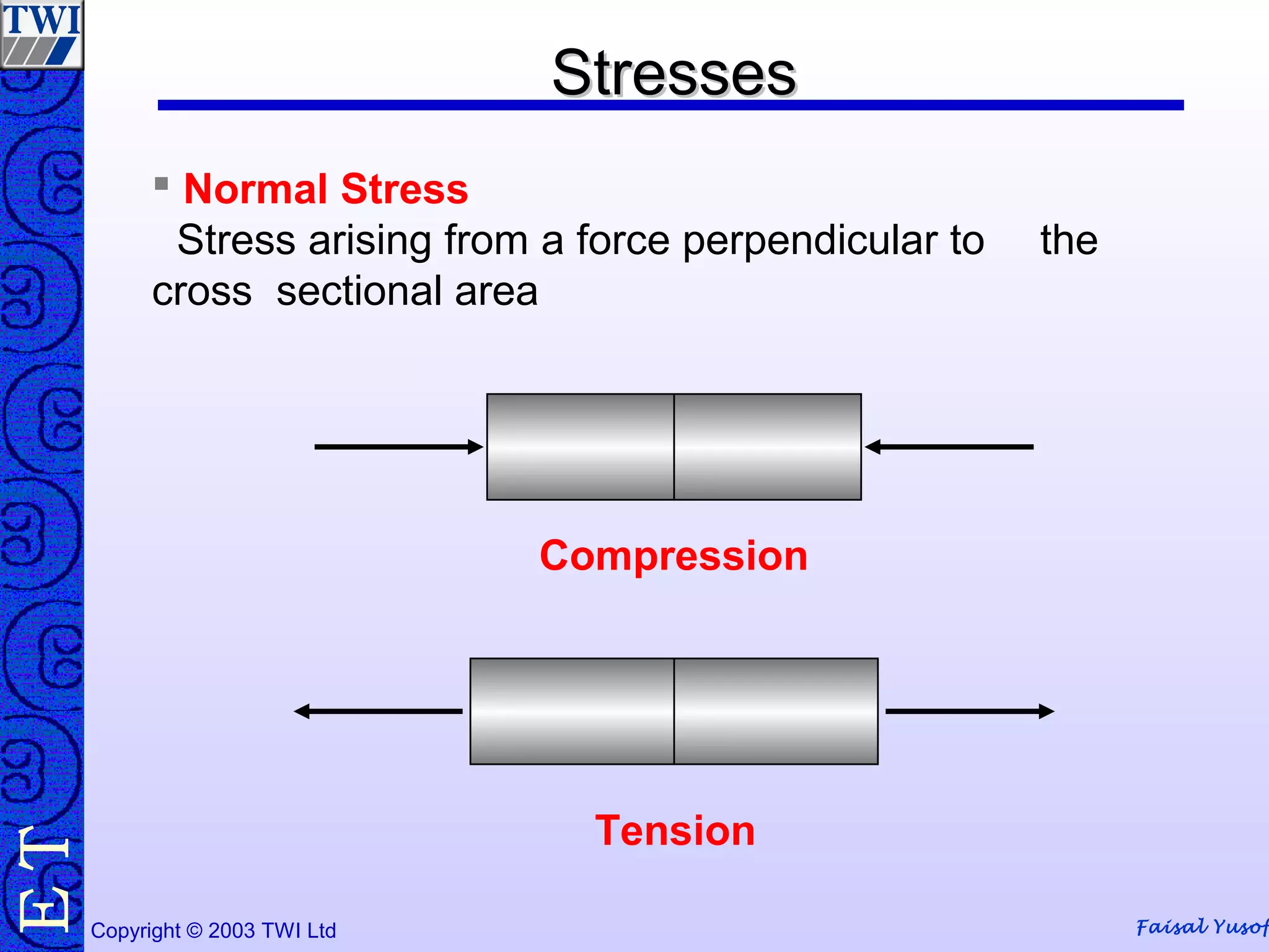


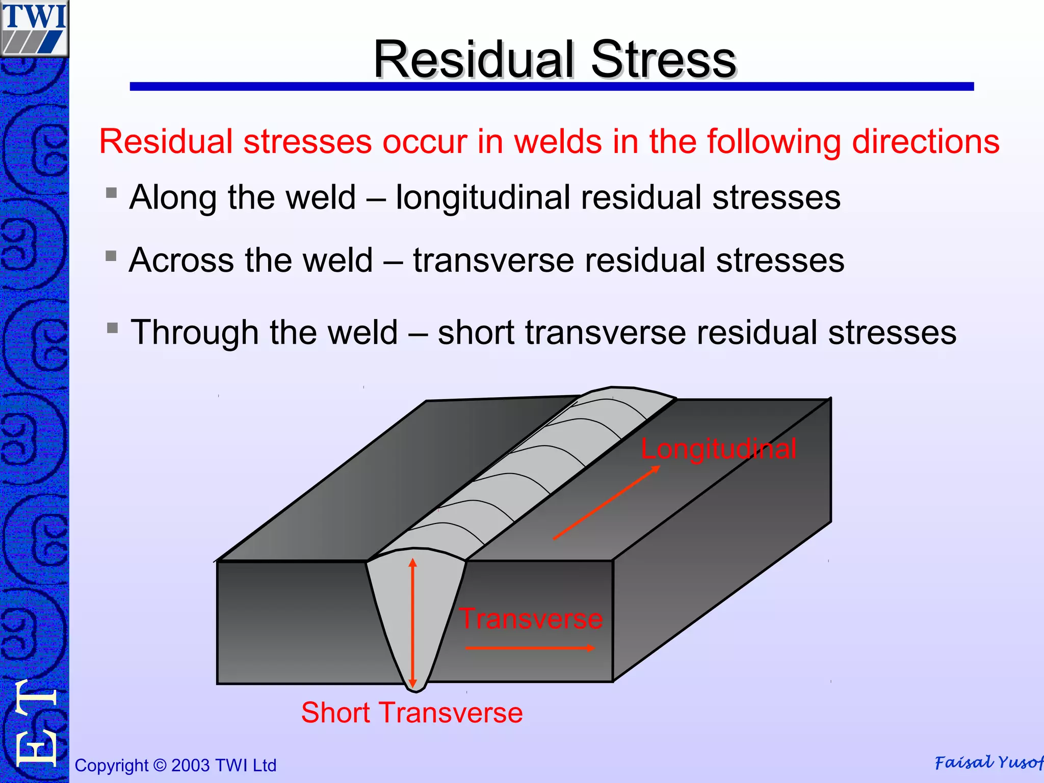


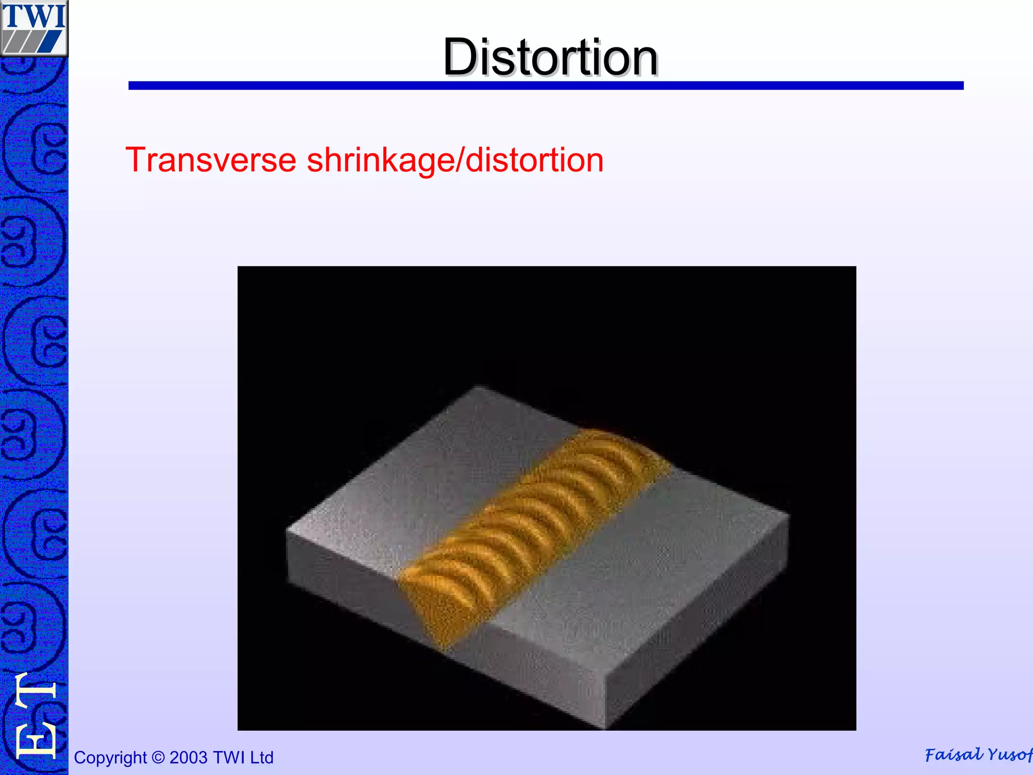

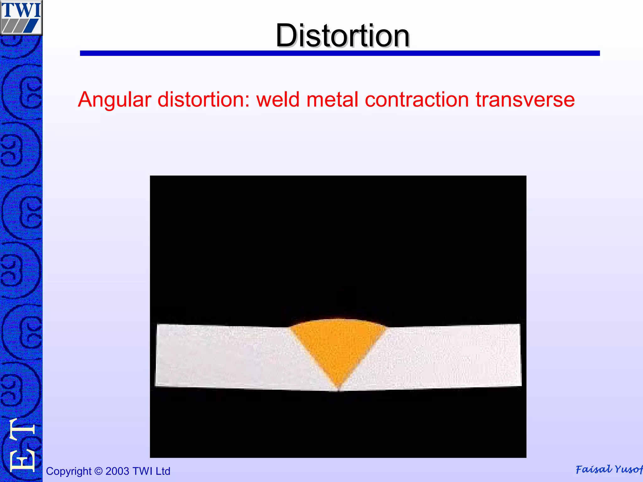
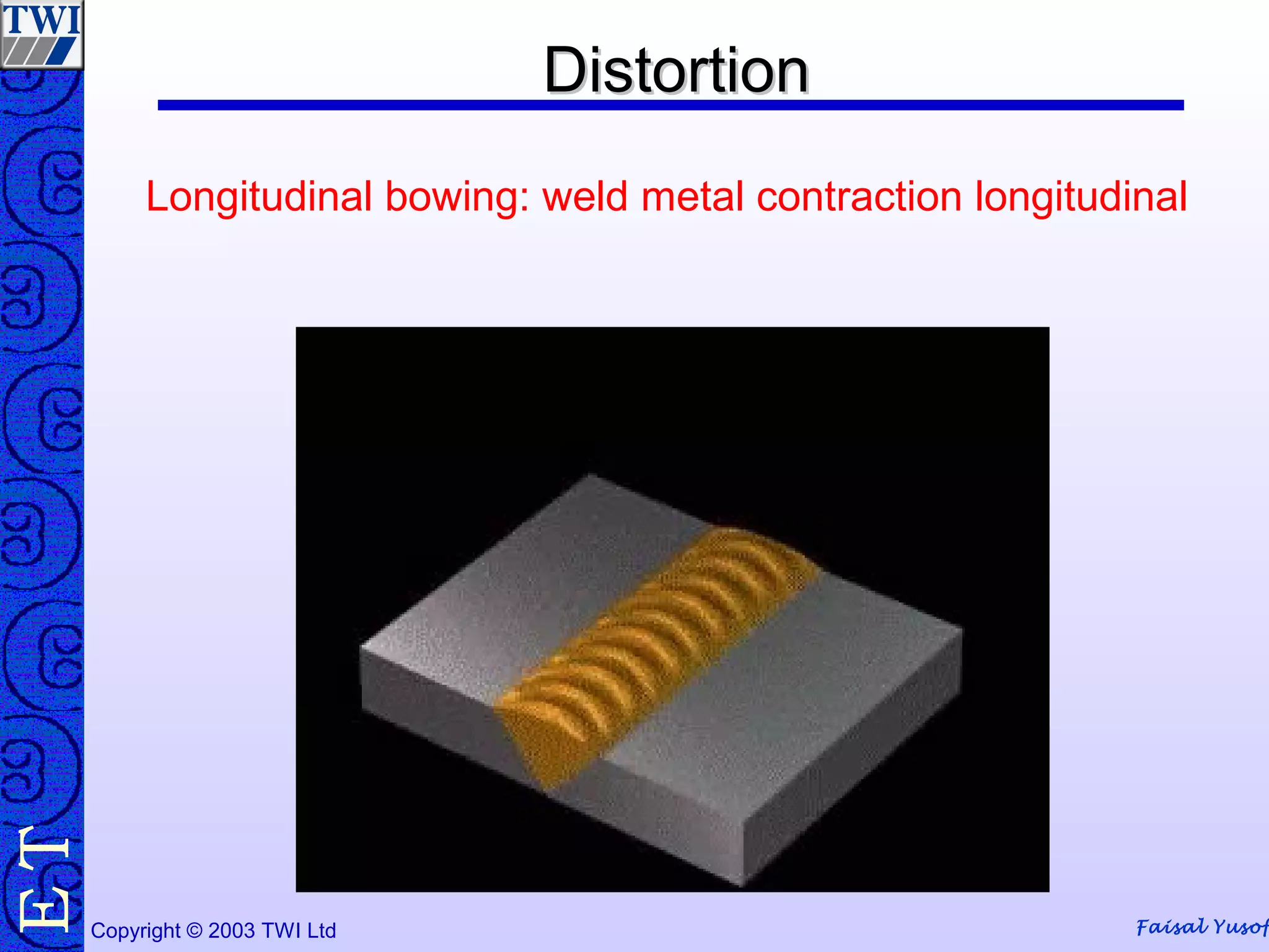
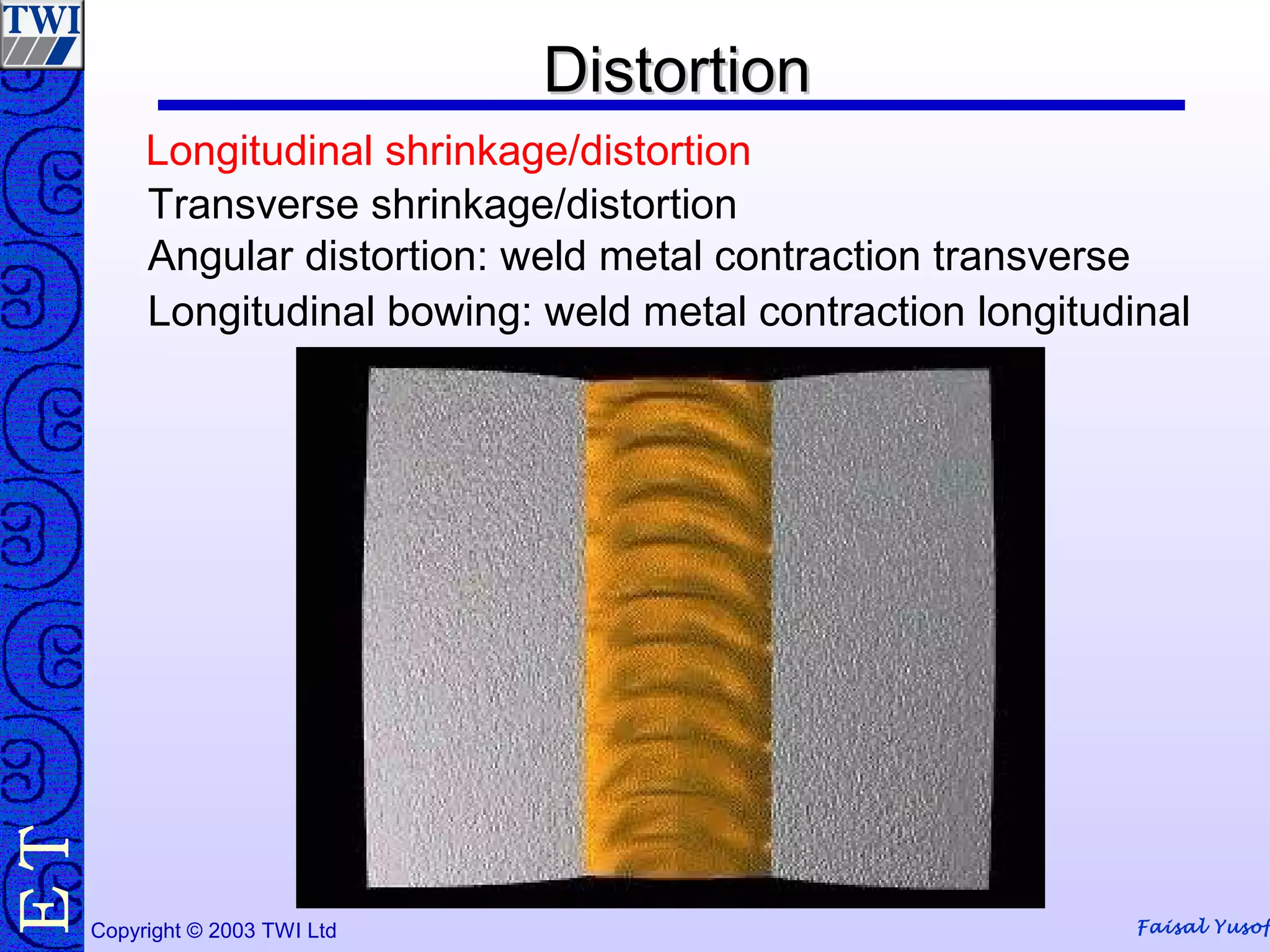
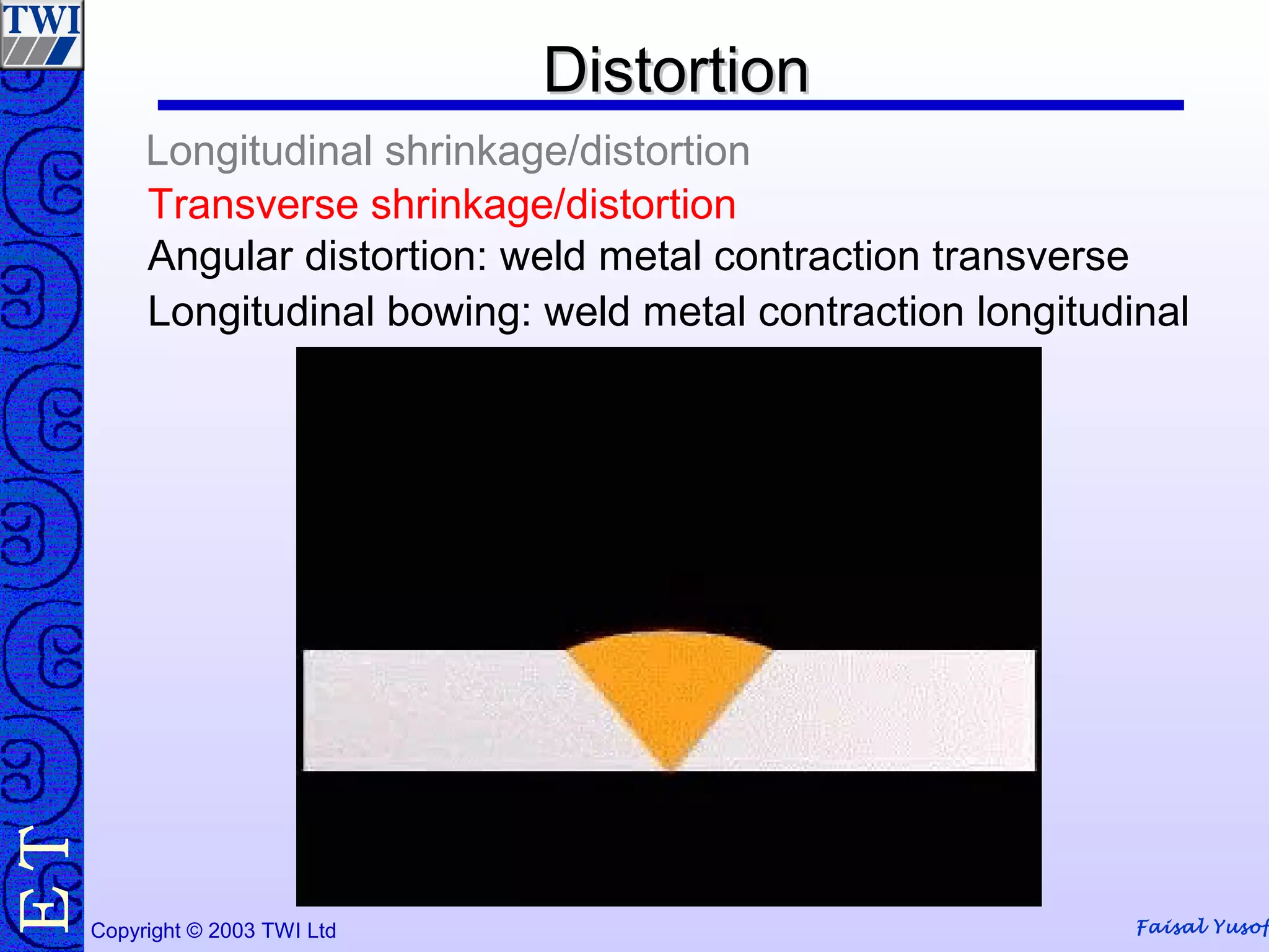

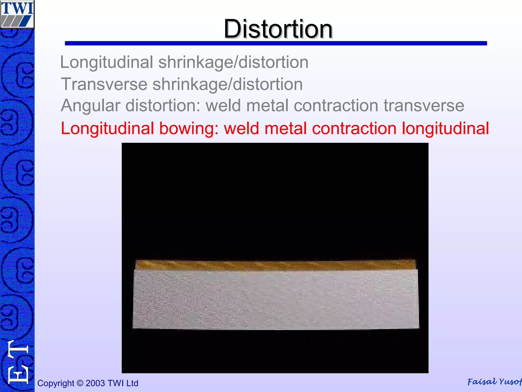
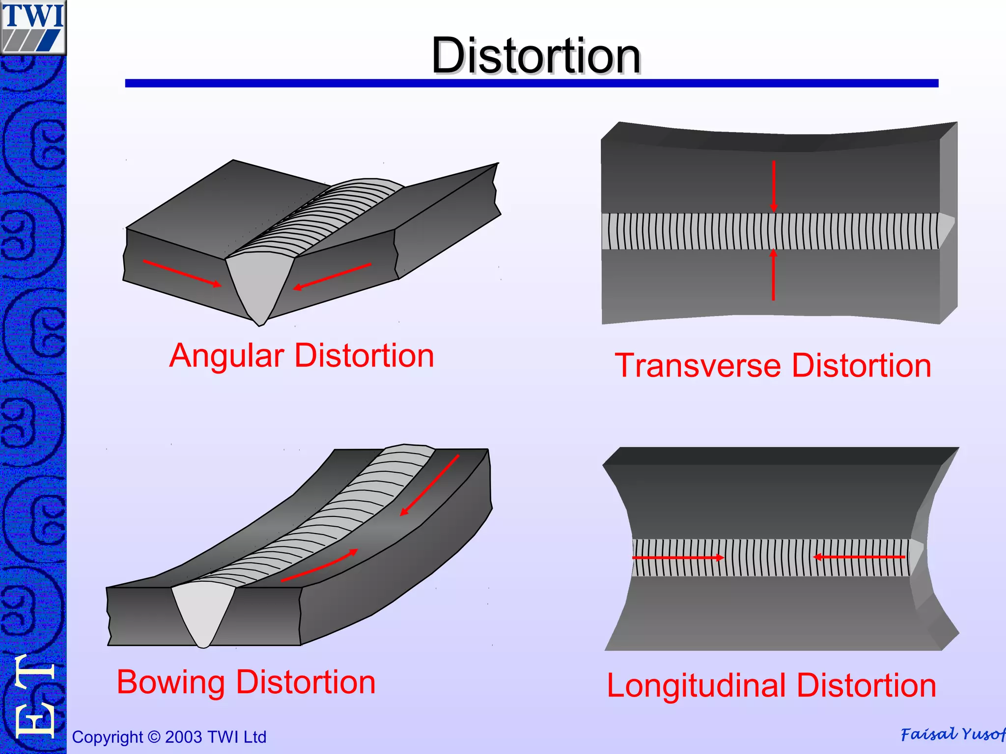


The document discusses residual stresses and distortion that occur during welding. It explains that residual stresses develop due to local expansion and contraction during welding, and are locked in as elastic strain. Distortion results from the movement caused by these welding stresses. The document outlines various factors that influence residual stress and distortion, such as heat input, restraint, and weld metal volume. It also discusses different types of distortion and several techniques for controlling distortion, such as joint design, offsetting, balanced welding, and clamping.


![Vibe Coding vs. Spec-Driven Development [Free Meetup]](https://cdn.slidesharecdn.com/ss_thumbnails/vibecodingvsspecdrivendevelopment-251209105622-43f455e7-thumbnail.jpg?width=640&height=640&fit=bounds)


