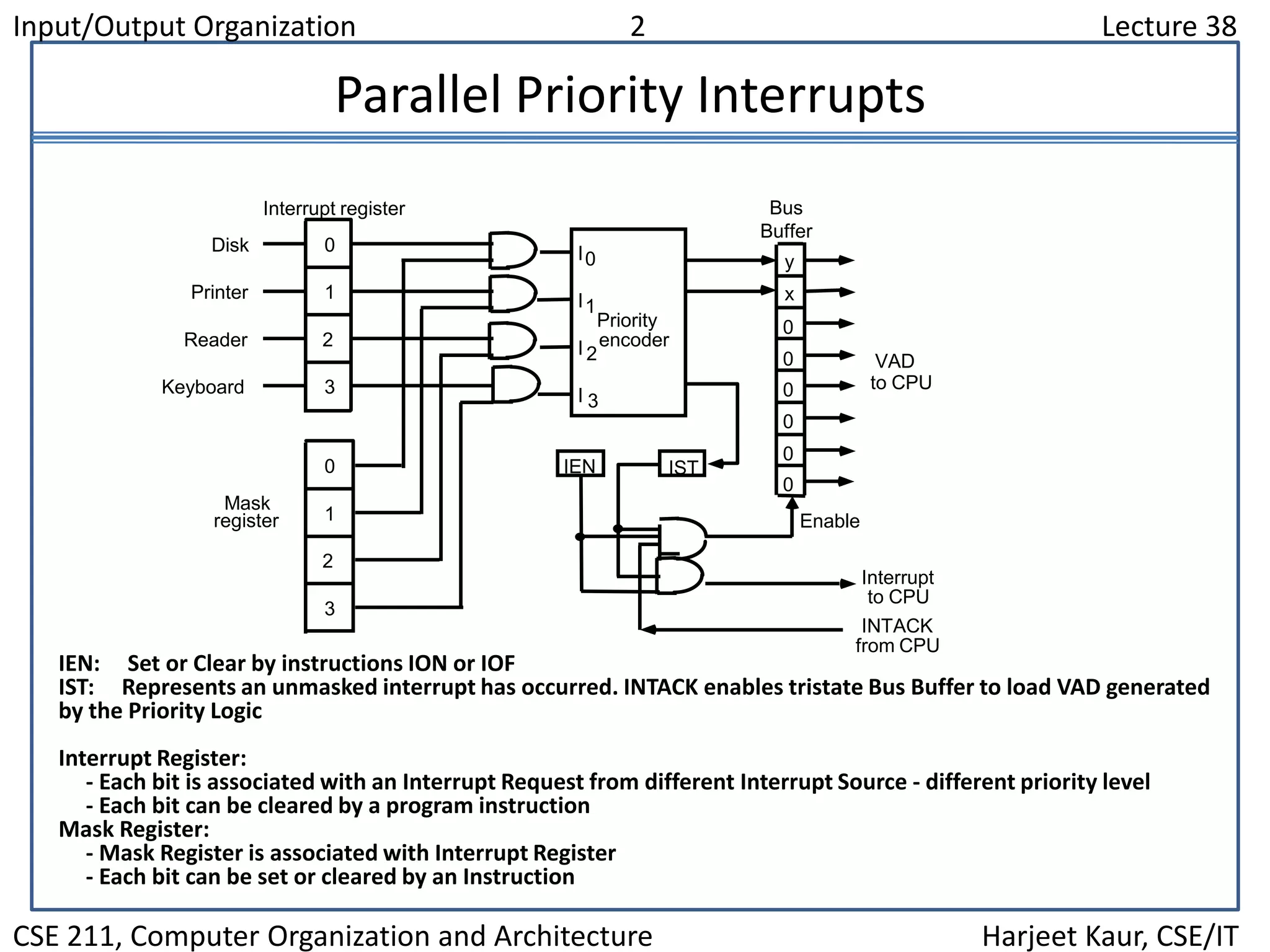
Input/Output Organization 1 Lecture 38
CSE 211, Computer Organization and Architecture Harjeet Kaur, CSE/IT
Overview
 Peripheral Devices
 Input-Output Interface
 Asynchronous Data Transfer
 Modes of Transfer
 Priority Interrupt
 Direct Memory Access
 Input-Output Processor
 Serial Communication
Input/Output Organization 2 Lecture 38
CSE 211, Computer Organization and Architecture Harjeet Kaur, CSE/IT
Parallel Priority Interrupts
Mask
register
INTACK
from CPU
Priority
encoder
I0
I1
I 2
I 3
0
1
2
3
y
x
ISTIEN0
1
2
3
0
0
0
0
0
0
Disk
Printer
Reader
Keyboard
Interrupt register
Enable
Interrupt
to CPU
VAD
to CPU
Bus
Buffer
IEN: Set or Clear by instructions ION or IOF
IST: Represents an unmasked interrupt has occurred. INTACK enables tristate Bus Buffer to load VAD generated
by the Priority Logic
Interrupt Register:
- Each bit is associated with an Interrupt Request from different Interrupt Source - different priority level
- Each bit can be cleared by a program instruction
Mask Register:
- Mask Register is associated with Interrupt Register
- Each bit can be set or cleared by an Instruction
Input/Output Organization 3 Lecture 38
CSE 211, Computer Organization and Architecture Harjeet Kaur, CSE/IT
Priority Encoder
Determines the highest priority interrupt when more than one
interrupts take place
Priority Encoder Truth table
1 d d d
0 1 d d
0 0 1 d
0 0 0 1
0 0 0 0
I0 I1 I2 I3
0 0 1
0 1 1
1 0 1
1 1 1
d d 0
x y IST
x = I0' I1'
y = I0' I1 + I0’ I2’
(IST) = I0 + I1 + I2 + I3
Inputs Outputs
Boolean functions
Input/Output Organization 4 Lecture 38
CSE 211, Computer Organization and Architecture Harjeet Kaur, CSE/IT
Interrupt Cycle
At the end of each Instruction cycle
- CPU checks IEN and IST
- If IEN  IST = 1, CPU -> Interrupt Cycle
SP SP - 1 Decrement stack pointer
M[SP]  PC Push PC into stack
INTACK  1 Enable interrupt acknowledge
PC  VAD Transfer vector address to PC
IEN  0 Disable further interrupts
Go To Fetch to execute the first instruction
in the interrupt service routine
Input/Output Organization 5 Lecture 38
CSE 211, Computer Organization and Architecture Harjeet Kaur, CSE/IT
Initial and Final Operations
JMP PTR
JMP RDR
JMP KBD
JMP DISK0
1
2
3
Program to service
magnetic disk
Program to service
line printer
Program to service
character reader
Program to service
keyboard
DISK
PTR
RDR
KBD
255
256
750
256
750
Stack
Main program
current instr.749
KBD
interrupt
2
VAD=00000011 3
4
Disk
interrupt
5
6
7
8
9 10
11
1
Initial and Final Operations
Each interrupt service routine must have an initial and final set of
operations for controlling the registers in the hardware interrupt system
Initial Sequence
[1] Clear lower level Mask reg. bits
[2] IST <- 0
[3] Save contents of CPU registers
[4] IEN <- 1
[5] Go to Interrupt Service Routine
Final Sequence
[1] IEN <- 0
[2] Restore CPU registers
[3] Clear the bit in the Interrupt Reg
[4] Set lower level Mask reg. bits
[5] Restore return address, IEN <- 1

Lecture 38

  • 1.
    Input/Output Organization 1Lecture 38 CSE 211, Computer Organization and Architecture Harjeet Kaur, CSE/IT Overview  Peripheral Devices  Input-Output Interface  Asynchronous Data Transfer  Modes of Transfer  Priority Interrupt  Direct Memory Access  Input-Output Processor  Serial Communication
  • 2.
    Input/Output Organization 2Lecture 38 CSE 211, Computer Organization and Architecture Harjeet Kaur, CSE/IT Parallel Priority Interrupts Mask register INTACK from CPU Priority encoder I0 I1 I 2 I 3 0 1 2 3 y x ISTIEN0 1 2 3 0 0 0 0 0 0 Disk Printer Reader Keyboard Interrupt register Enable Interrupt to CPU VAD to CPU Bus Buffer IEN: Set or Clear by instructions ION or IOF IST: Represents an unmasked interrupt has occurred. INTACK enables tristate Bus Buffer to load VAD generated by the Priority Logic Interrupt Register: - Each bit is associated with an Interrupt Request from different Interrupt Source - different priority level - Each bit can be cleared by a program instruction Mask Register: - Mask Register is associated with Interrupt Register - Each bit can be set or cleared by an Instruction
  • 3.
    Input/Output Organization 3Lecture 38 CSE 211, Computer Organization and Architecture Harjeet Kaur, CSE/IT Priority Encoder Determines the highest priority interrupt when more than one interrupts take place Priority Encoder Truth table 1 d d d 0 1 d d 0 0 1 d 0 0 0 1 0 0 0 0 I0 I1 I2 I3 0 0 1 0 1 1 1 0 1 1 1 1 d d 0 x y IST x = I0' I1' y = I0' I1 + I0’ I2’ (IST) = I0 + I1 + I2 + I3 Inputs Outputs Boolean functions
  • 4.
    Input/Output Organization 4Lecture 38 CSE 211, Computer Organization and Architecture Harjeet Kaur, CSE/IT Interrupt Cycle At the end of each Instruction cycle - CPU checks IEN and IST - If IEN  IST = 1, CPU -> Interrupt Cycle SP SP - 1 Decrement stack pointer M[SP]  PC Push PC into stack INTACK  1 Enable interrupt acknowledge PC  VAD Transfer vector address to PC IEN  0 Disable further interrupts Go To Fetch to execute the first instruction in the interrupt service routine
  • 5.
    Input/Output Organization 5Lecture 38 CSE 211, Computer Organization and Architecture Harjeet Kaur, CSE/IT Initial and Final Operations JMP PTR JMP RDR JMP KBD JMP DISK0 1 2 3 Program to service magnetic disk Program to service line printer Program to service character reader Program to service keyboard DISK PTR RDR KBD 255 256 750 256 750 Stack Main program current instr.749 KBD interrupt 2 VAD=00000011 3 4 Disk interrupt 5 6 7 8 9 10 11 1 Initial and Final Operations Each interrupt service routine must have an initial and final set of operations for controlling the registers in the hardware interrupt system Initial Sequence [1] Clear lower level Mask reg. bits [2] IST <- 0 [3] Save contents of CPU registers [4] IEN <- 1 [5] Go to Interrupt Service Routine Final Sequence [1] IEN <- 0 [2] Restore CPU registers [3] Clear the bit in the Interrupt Reg [4] Set lower level Mask reg. bits [5] Restore return address, IEN <- 1