Development of Transient Liquid Phase Sintering (TLPS) for MLCCs
•
4 likes•4,272 views

1) The document presents research on developing novel leaded multilayer ceramic capacitors (MLCC) using transient liquid phase sintering (TLPS) materials for applications requiring reliability at temperatures over 175°C. 2) Two TLPS materials are characterized: Cu-Sn, which forms a metal matrix composite bond; and In-Ag, which forms a solid solution bond using a single metal paste diffusion process. 3) Testing shows both TLPS materials have higher maximum shear strength than common solders up to 300°C, indicating their potential as lead-free, high-temperature alternatives to solders for electronic interconnects.

Recommended
More Related Content
What's hot
What's hot (20)
Viewers also liked
Viewers also liked (16)
Similar to Development of Transient Liquid Phase Sintering (TLPS) for MLCCs
Similar to Development of Transient Liquid Phase Sintering (TLPS) for MLCCs (20)
More from KEMET Electronics Corporation
More from KEMET Electronics Corporation (13)
Recently uploaded
Recently uploaded (20)
Development of Transient Liquid Phase Sintering (TLPS) for MLCCs
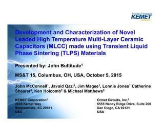
- 1. Development and Characterization of Novel Leaded High Temperature Multi-Layer Ceramic Capacitors (MLCC) made using Transient Liquid Phase Sintering (TLPS) Materials Presented by: John Bultitude1 MS&T 15, Columbus, OH, USA, October 5, 2015 John McConnell1, Javaid Qazi1, Jim Magee1, Lonnie Jones1 Catherine Shearer2, Ken Holcomb2 & Michael Matthews2 KEMET Corporation1 Ormet Circuits, Inc.2 2835 Kemet Way 6555 Nancy Ridge Drive, Suite 200 Simpsonville, SC 29681 San Diego, CA 92121 USA USA
- 2. Introduction • Leaded MLCC can absorb larger CTE mismatches than surface mounted components making them suitable for higher temperature electronics that require reliable performance operating at ≥ 175oC • The processing temperatures for these electronic assemblies have been increasing, in some cases ≥ 300oC, with components required to survive multiple heating cycles • These requirements surpass the capability of established interconnect materials such as common solders and welds • The performance novel Pb-free transient liquid phase sintering (TLPS) materials at temperatures up to 300oC are compared to these common interconnects
- 3. Presentation Outline • High Temperature Electronics – Trends by Market, Assembly Needs & Environmental Legislation • Current Solder Capability – Maximum Shear testing • Transient Liquid Phase Sintering (TLPS) – Comparison to solders • Leaded MLCC TLPS Capacitor Trials – TLPS Cu-Sn for Radial & Axial Leaded MLCC – TLPS In-Ag for Stacked MLCC using a Single Metal Paste Diffusion Process – Microstructures & performance comparisons to solders • Summary • Conclusion & Future Work
- 4. Market Trends and Drivers for High Temperature Electronics 350oC 325oC 300oC 250oC 200oC 150oC 275oC 225oC 175oC 125oC 2015 2016 2017 2018 Aerospace Engine Control & Monitoring Systems Downhole Automotive Downhole Deeper Wells Automotive Engine Control & Monitoring Systems Geothermal Military Power-Semi Wide Band-gap Semi- Conductors SiC, GaN 2019 Aerospace
- 5. Electronic Process & Operating Temperatures AuGe or AuSi Solder $$$$$$$ Pb-Free RoHS 2 Compliant by July 22, 2016 -ELV Process/OperatingTemp. 1950 1970 1990 2010 2020 Years Hi Sn Solders, 60Sn40Pb,63Sn37Pb etc. Hi Pb Solder alloys: 10Sn/88Pb/2Ag, 95Pb/5Sn TLPS 160oC to > 800oC RoHS Compliant Interconnect 200oC 400oC 300oC 500oC 600oC Lead Free solders SAC Alloys, SnSb Transient Liquid Phase Sintering TLPS: • Low Processing temp. • High Re-melt temp. • Pb-Free & RoHS Compliant Potential Extension for > 85% Pb-containing solders to 2021
- 6. Assembly Sequences vs Heat Cycles Board Level Assembly surface mount 1 reflow SM Component 1st Solder Reflow Overmolding Component Assembly 1st Solder Reflow + + Leads Board Level Assembly components seeing 2nd reflow 2 Solder Reflows: Lead + Board + Overmolding 275oC to 350oC Module Sub-Assembly 2 Solder Reflows: Lead + Board Board Level Assembly components seeing 3rd reflow + 3 Solder Reflows: Lead + Mod + Overmold + Board Assembly IncreasingAssembly/Processing Complexity
- 7. Shear Testing of Solders Shear StressTesting Ref. John Bultitude et al; Journal of Microelectronics & Electronic Packaging (2014), 11, 166-173 • Leads were attached to case size 4060 MLCC with selected solders • Pull tests were performed at temperatures up to 300oC • The average maximum shear stress at 0.1mm/sec was calculated for the samples at different temperatures
- 8. Maximum Shear Stress @ High Temperatures Selected Solders
- 9. What is TLPS? – Low temperature reaction of low melting point metal or alloy with a high melting point metal or alloy to form a reacted metal matrix – Forms a metallurgical bond between 2 surfaces How does it compare to solder? – Bonding is specific to surface type & TLPS used – Applied as a paste or preform or plated surface-to-surface – Active fluxes to clean surfaces & bond oxide/contaminants – Polymeric binders retained in joint – No rework is possible – No wetting or fillet formation – No solder ball formation – TLPS has much higher re-melt > 600oC depending on the specific alloys formed TLPS Introduction & Solder Comparison
- 10. Maximum Temperature Capability KEMET Hanging Weight Test Temperature of Joint Failure Support Bar Suspended Parts 30 g weights • Box Kiln Temperature is increased in steps until joint fails • Solders fail close to melting points
- 11. Leaded MLCC TLPS Capacitor Trials Radial 1206, 1µF, 50V X8L Axial 0805, 1nF & 1206, 47nF, 50V C0G Cu –TLPS Cu-Sn – Cu Bonds Conformal Coating Ag – In(Ag) Single Metal Paste Diffusion – Ag Bonds Stack 2220, 0.1µF, 630V C0G US Patent Number 8,902,565 B2 & Pending Patents
- 12. TLPS Materials & Processes 1. TLPS Cu-Sn – Metal Matrix Composite Bond – Single Stage Sintering Process ~ 300oC peak temperature < 30 sec. • Maximum Shear Strength Vs. Solders to 300oC (Overmolding Capability) • Long term performance testing results @ 175oC (Operation) • Microstructures and mechanical performance comparisons 2. TLPS In-Ag by Single Metal Paste Diffusion (SMPD) – Solid Solution Bond – Two stage SMPD process • Process Development • Microstructures & mechanical performance comparisons • Maximum Shear Strength Vs. Solders to 300oC
- 13. Maximum Shear @ High Temperature Radial MLCC TLPS Cu-Sn Operating Temperature Overmolding Temperature
- 14. Maximum Shear Stress @ Temperature Trends for Solders & TLPS Cu-Sn R2 values for solders all > 0.96
- 15. Temperature & Shear Capability for Solders & TLPS Cu-Sn Interconnect Melting Point (oC) Zero Shear Intercept Temperature (oC) 10Sn/88Pb/2Ag Solder 290 299 93.5Pb/5Sn/1.5Ag Solder 305 360 91.5Sn/8.5Sb Solder 240 269 SAC 305 Solder 217 265 TLPS Cu-Sn ~ 660 352 • Zero Shear for all solders is above their melting points • Zero Shear for TLPS Cu-Sn is below the melting point so useful range is at higher temperatures > 300oC
- 16. TLPS Cu-Sn Microstructure Vs. Solder • Microstructure consists of copper in copper-tin, a Metal Matrix Composite *CuSn Intermetallics formed at SAC solder interface *Ref. Catherine Shearer et al; IMAPs 2015; paper submitted • Growth of Cu-Sn intermetallics associated joint embrittlement are of great concern with respect to joint robustness TLPS Cu-Sn SAC 305 Solder
- 17. TLPS Cu-Sn Extended Testing • Axial Samples were tested as follows: • No failures in TLPS * Failure at 2000hrs cycling was due to fracture of MLCC • 0805 parts were sheared before and after these tests: • Cycling decreases maximum shear stress by ~ 40% but this remains acceptable Ref. John McConnell et al; IMAPs 2015; paper submitted Test 1nF 47nF High Temp. Storage 175oC Air 2000 hours 0/20 0/20 Load Humidity 85oC/85%RH 50V 2000 hours 0/20 0/20 Thermal Cycling -40 to 175oC 2000 cycles (30oC/min. ramp; 30 min. dwell) - Mounted 1/20* 0/20
- 18. TLPS Cu-Sn Microstructure 2000hrs @ 175oC EDS Analysis of Atomic Ratio’s: • Ag/Sn ~ 3; Ag3Sn • Cu/Sn ~ 1.2; Cu5Sn6 • Cu/Sn ~ 3; Cu3Sn Cu Cu
- 19. Cu-Sn and Ag-Sn Binary Phase Diagrams http://www.metallurgy.nist.gov/phase/solder/agsn.html http://www.metallurgy.nist.gov/phase/solder/cusn.htm
- 20. TLPS Cu-Sn Shear Test Failures 2000hrs @ 175oC In sheared samples micro-cracks terminate at the Cu spheres in the Metal Matrix Composite
- 21. TLPS Cu-Sn Shear Test Failures 2000hrs @ 175oC Fractures meander through the Metal Matrix Composite
- 22. TLPS In-Ag • Review our development of TLPS bonding using In-Ag for stacked MLCC with no conformal coatings • Initial tests were run on forming bonds by diffusion between plated metal surfaces but the surfaces of leads and MLCC are not planar making it difficult to form a large contact area • For this reason we developed a Single Metal Paste Diffusion (SMPD) process
- 23. Single Metal Paste Diffusion (SMPD) Process Ag Lead Ag MLCC Indium Paste Initial Bond Formation • Low Pressure • 250-350oC/30seconds • N2 atmosphere Ag Lead Ag MLCC In Ag Ag InAg Diffusion • 200-300oC • N2 atmosphere Low Ag 500X High Ag 1000X Low Ag 500X 48hrs 200oC High Ag 1000X 120hrs 200oC US Patent Number 8,902,565 B2 & Pending Patents
- 24. Peel Strength Vs. Diffusion Time
- 25. TLPS In-Ag Microstructures High Ag • The SMPD process results in an In-Ag Solid Solution Bond
- 26. In-Ag Binary Phase Diagram Ref. Z. Moser et al; Journal of Electronic Materials (2001), Volume 30, Issue 9, 1120-1128 > Hot Peel Strength
- 27. Maximum Shear Stress @ Temperature Trends for Solders & TLPS Cu-Sn & In-Ag
- 28. Temperature Capability & Shear Capability Trends for Solders & TLPS In-Ag Interconnect Melting Point (oC) Zero Shear Intercept Temperature (oC) 10Sn/88Pb/2Ag Solder 290 299 93.5Pb/5Sn/1.5Ag Solder 305 360 91.5Sn/8.5Sb Solder 240 269 SAC 305 Solder 217 265 TLPS Cu-Sn ~ 660 352 TLPS In-Ag (High Ag SMPD Process) ~ 780 355 • Zero Shear calculation is based on poor fit for TLPS In-Ag • At 300oC Maximum Shear for TLPS In-Ag is 2 X higher than TLPS Cu-Sn • Further refinement of our Single Metal Paste Diffusion (SMPD) process is underway to improve the performance of TLPS In-Ag at temperatures > 200oC
- 29. Summary • A CuSn based TLPS has been used to manufacture Radial & Axial Leaded MLCC with – Maximum Shear Stress > Pb-based solders @ 300oC – No TLPS failures through 175oC storage, cycling & biased humidity • On shear testing micro-cracks in the Metal Matrix Composite form and terminate at Cu spheres with fractures meandering through the TLPS • A Single Metal Paste Diffusion Process has been developed and used in MLCC stacks with – Solid Solution bonds of In-Ag – High peel strengths @ 200oC – Maximum Shear Stress > Pb-based solders @ 300oC & also higher than for TLPS Cu-Sn
- 30. Conclusion & Future Work • TLPS interconnects appears to be a suitable alternative to high-Pb solders for leaded MLCC • More extensive work is underway to – Refine & scale-up the lead attachment processes – Test at higher temperatures ≥ 200oC for longer times – Evaluate cycling to higher temperatures – Test mechanical shock performance
- 31. Acknowledgements • Thanks to our technicians Garry Renner, Jeff Bell and Jeff Murrell for their help supporting these developments
- 32. More Information • Available at: https://ec.kemet.com/tlps www.ormetcircuits.com • ‘High temperature capacitors and transient liquid phase interconnects for Pb-solder replacement’ review in Journal of Materials Science: Materials in Electronics