Download as PDF, PPTX


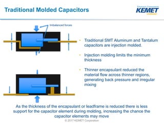
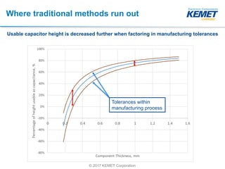
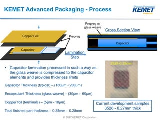

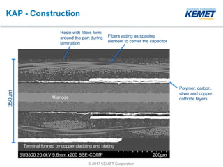

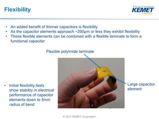
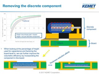

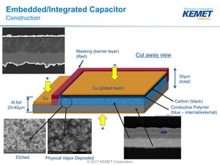

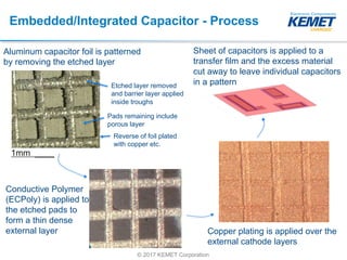

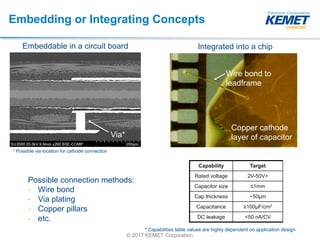


This document discusses KEMET's development of thin aluminum polymer capacitors for embedded applications. It begins by explaining the industry push for thinner components to increase power density. Traditional molding limits thickness reduction. KEMET's advanced packaging process called KAP uses lamination and copper plating to construct thinner capacitors down to 0.25mm. KAP offers higher volumetric efficiency than traditional and facedown packages. The document also explores flexible capacitors, embedded capacitors that can be integrated directly into circuit boards, and a process for patterning and transporting thin capacitor arrays. The goal is to maximize the percentage of height used for capacitance.


