SlideShare a Scribd company logo
1 of 62
Download to read offline
BREAKING THE BARRIERS TO
TRUE AUGMENTED REALITY
CHRISTIAN SANDOR
CHRISTIAN@SANDOR.COM
KEYNOTE AT 23RD INTERNATIONAL DISPLAY WORKSHOP
FUKUOKA, JAPAN
7 DECEMBER 2016
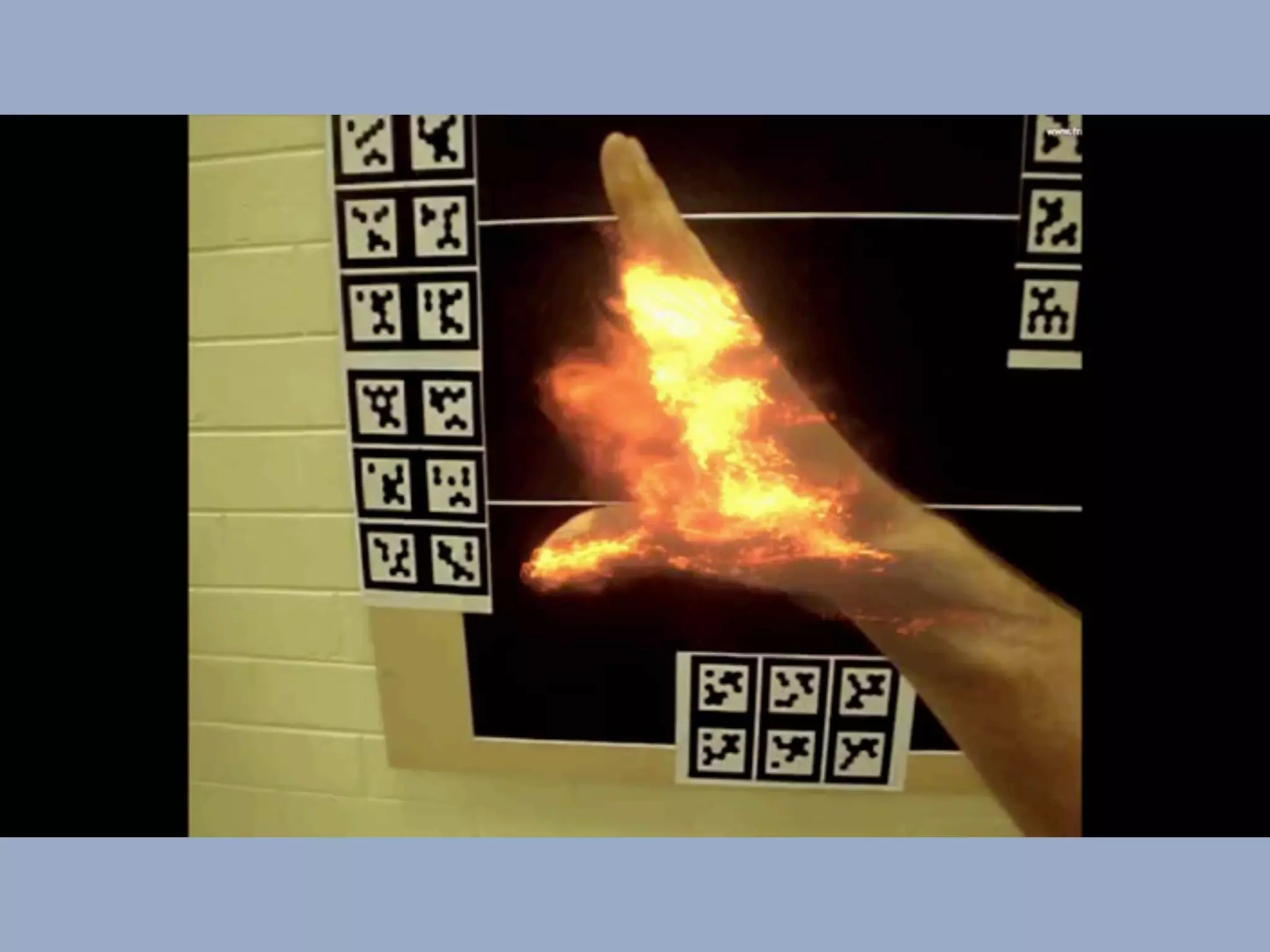
BURNAR: FEEL THE HEAT
MATT SWOBODA, THANH NGUYEN, ULRICH ECK, GERHARD REITMAYR, STEFAN HAUSWIESNER,
RENE RANFTL, AND CHRISTIAN SANDOR. DEMO AT IEEE INTERNATIONAL SYMPOSIUM ON MIXED
AND AUGMENTED REALITY, BASEL, SWITZERLAND, OCTOBER 2011. BEST DEMO AWARD
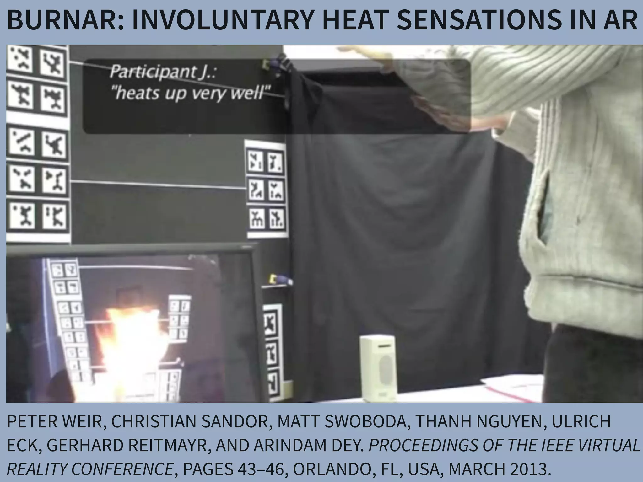
BURNAR: INVOLUNTARY HEAT SENSATIONS IN AR
PETER WEIR, CHRISTIAN SANDOR, MATT SWOBODA, THANH NGUYEN, ULRICH
ECK, GERHARD REITMAYR, AND ARINDAM DEY. PROCEEDINGS OF THE IEEE VIRTUAL
REALITY CONFERENCE, PAGES 43–46, ORLANDO, FL, USA, MARCH 2013.
WORKSHOP AT NAIST, AUGUST 2014
ARXIV E-PRINTS, ARXIV:1512.05471 [CS.HC], 13 PAGES
HTTP://ARXIV.ORG/ABS/1512.05471
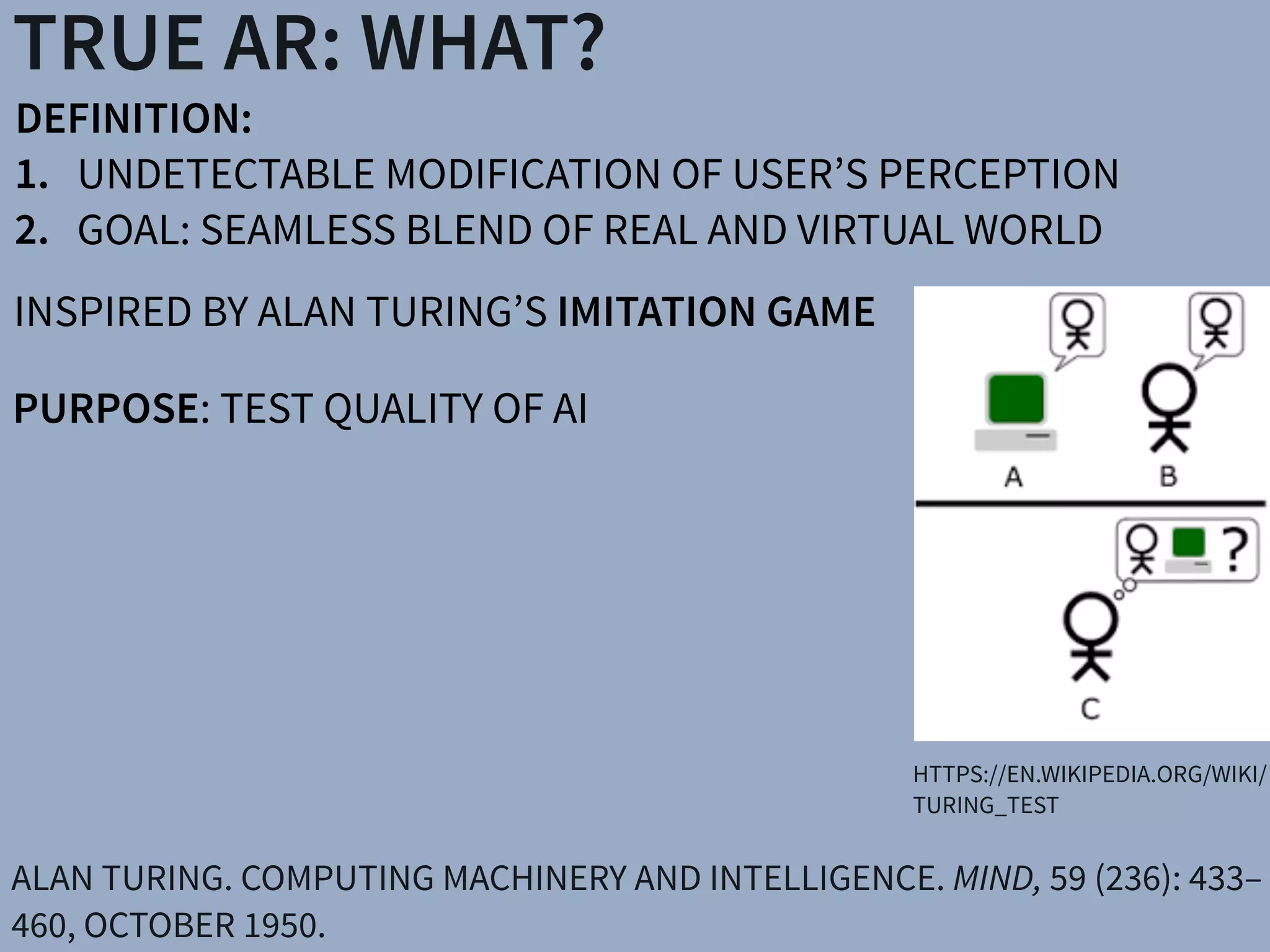
DEFINITION:
1. UNDETECTABLE MODIFICATION OF USER’S PERCEPTION
2. GOAL: SEAMLESS BLEND OF REAL AND VIRTUAL WORLD
TRUE AR: WHAT?
HTTPS://EN.WIKIPEDIA.ORG/WIKI/
TURING_TEST
ALAN TURING. COMPUTING MACHINERY AND INTELLIGENCE. MIND, 59 (236): 433–
460, OCTOBER 1950.
INSPIRED BY ALAN TURING’S IMITATION GAME
PURPOSE: TEST QUALITY OF AI
RELATION TO OTHER TURING TESTS
COMPUTER GRAPHICS: MICHAEL D. MCGUIGAN.
GRAPHICS TURING TEST. ARXIV E-PRINTS, ARXIV:CS/
0603132V1, 2006
VISUAL COMPUTING: QI SHAN, RILEY ADAMS, BRIAN
CURLESS, YASUTAKA FURUKAWA, STEVEN M. SEITZ:
THE VISUAL TURING TEST FOR SCENE
RECONSTRUCTION. 3DV 2013: 25-32
VIRTUAL REALITY
AUGMENTED REALITY
DIFFICULTY
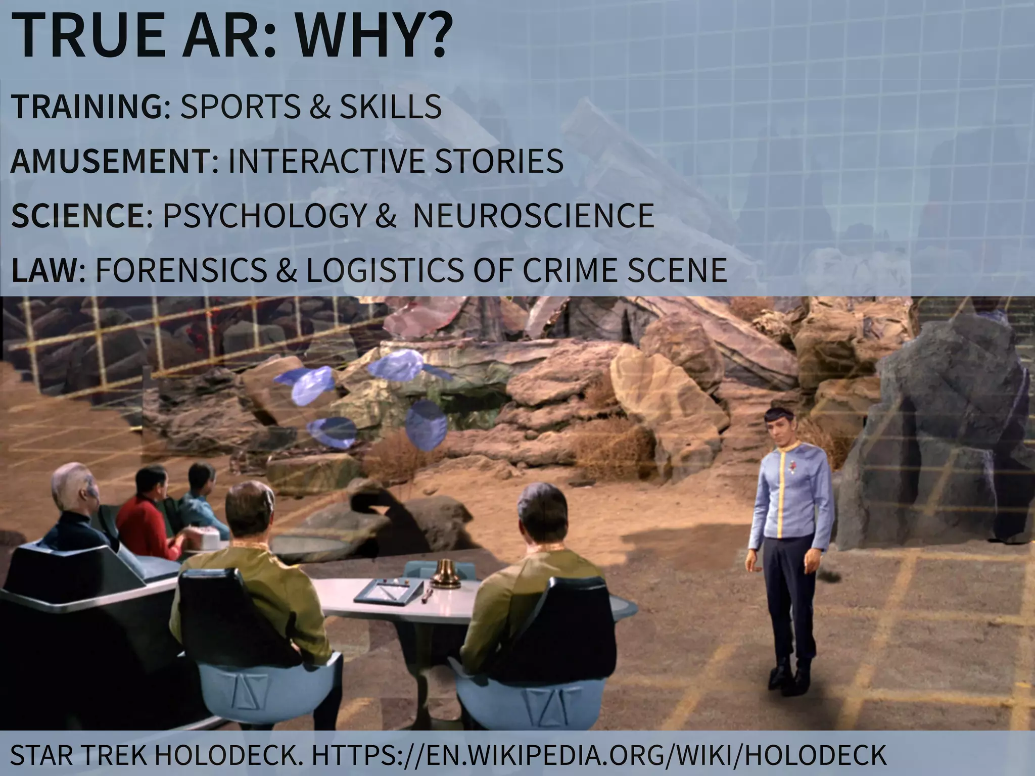
TRUE AR: WHY?
TRAINING: SPORTS & SKILLS
AMUSEMENT: INTERACTIVE STORIES
SCIENCE: PSYCHOLOGY & NEUROSCIENCE
LAW: FORENSICS & LOGISTICS OF CRIME SCENE
STAR TREK HOLODECK. HTTPS://EN.WIKIPEDIA.ORG/WIKI/HOLODECK
TRUE AR: HOW?
MANIPULATING 

ATOMS
MANIPULATING 

PERCEPTION
CONTROLLED
MATTER
PERSONALIZED AR IMPLANTED ARSURROUND
AR
There have been a number of shape displays based on pin
architecture. The FEELEX project [14] was one of the early
attempts to design combined shapes and computer graphics
displays that can be explored by touch. FEELEX consisted
of several mechanical pistons actuated by motors and cov-
ered by a soft silicon surface. The images were projected
onto its surface and synchronized with the movement of the
pistons, creating simple shapes.
Lumen [32] is a low resolution, 13 by 13-pixel, bit-map
display where each pixel can also physically move up and
down (Figure 4). The resulting display can present both 2D
graphic images and moving physical shapes that can be
observed, touched, and felt with the hands. The 2D position
sensor built into the surface of Lumen allows users to input
commands and manipulate shapes with their hands.
Other related project are PopUp and Glowbits devices [18,
33]. PopUp consists of an array of rods that can be moved
up and down using shape memory alloy actuators. The
PopUp, however, does not have a visual and interactive
component. Glowbits by Daniel Hirschmann (Figure 3) is a
2D array of rods with attached LEDs; the motorized rods
can move up and down and LEDs can change their colors.
Discussion
We have overviews a number of reasons why actuation can
be used in user interfaces. We summarize them in Table 1.
Applications Examples
Figure 2.7: Hand-fixed reference frame: Augmentations move w
example shows a user discussing a virtual map wit
map from di↵erent angles, he can pick it up from t
his belt and put it in his hand.
There have been a number of shape
architecture. The FEELEX project [14
attempts to design combined shapes a
displays that can be explored by touc
of several mechanical pistons actuate
ered by a soft silicon surface. The i
onto its surface and synchronized wit
pistons, creating simple shapes.
Lumen [32] is a low resolution, 13
display where each pixel can also ph
down (Figure 4). The resulting displa
graphic images and moving physica
observed, touched, and felt with the h
sensor built into the surface of Lumen
commands and manipulate shapes wit
Other related project are PopUp and
33]. PopUp consists of an array of ro
up and down using shape memory
PopUp, however, does not have a
component. Glowbits by Daniel Hirsc
2D array of rods with attached LED
can move up and down and LEDs can
Discussion
We have overviews a number of reas
be used in user interfaces. We summa
SACHIKO KODAMA. PROTRUDE, FLOW. ACM
SIGGRAPH 2001 ART GALLERY.
HTTP://PIXIEDUSTTECH.COM
CONTROLLED MATTER
HTTP://TANGIBLE.MEDIA.MIT.EDU/

PROJECT/INFORM
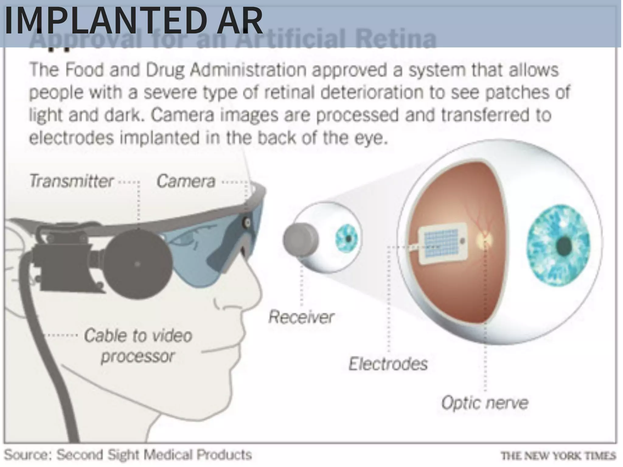
IMPLANTED AR
SURROUND VS. PERSONALIZED AR
MANIPULATING 

ATOMS
MANIPULATING 

PERCEPTION
CONTROLLED
MATTER
PERSONALIZED AR IMPLANTED ARSURROUND
AR
There have been a number of shape displays based on pin
architecture. The FEELEX project [14] was one of the early
attempts to design combined shapes and computer graphics
displays that can be explored by touch. FEELEX consisted
of several mechanical pistons actuated by motors and cov-
ered by a soft silicon surface. The images were projected
onto its surface and synchronized with the movement of the
pistons, creating simple shapes.
Lumen [32] is a low resolution, 13 by 13-pixel, bit-map
display where each pixel can also physically move up and
down (Figure 4). The resulting display can present both 2D
graphic images and moving physical shapes that can be
observed, touched, and felt with the hands. The 2D position
sensor built into the surface of Lumen allows users to input
commands and manipulate shapes with their hands.
Other related project are PopUp and Glowbits devices [18,
33]. PopUp consists of an array of rods that can be moved
up and down using shape memory alloy actuators. The
PopUp, however, does not have a visual and interactive
component. Glowbits by Daniel Hirschmann (Figure 3) is a
2D array of rods with attached LEDs; the motorized rods
can move up and down and LEDs can change their colors.
Discussion
We have overviews a number of reasons why actuation can
be used in user interfaces. We summarize them in Table 1.
Applications Examples
Figure 2.7: Hand-fixed reference frame: Augmentations move w
example shows a user discussing a virtual map wit
map from di↵erent angles, he can pick it up from t
his belt and put it in his hand.
LIGHT FIELD DISPLAYS:
PERCEIVABLE

SUBSET
FULL
onvergence of the eyes, and the distance of the
ated close to the horopter (see Section 4.4.1) can
ge around the horopter at which this is possible
rea. However, in addition to absolute disparity,
y-based depth perception. For example, the gra-
., the depth gradient) influence depth perception
depth perception content dependent. Further-
isparity is processed and depth is perceived can
conflicting cues (e.g., inconsistent convergence
ection 4.4.2) and nonconflicting cues, and an up-
modulation frequency of disparity exists. A good
ed depth perception can be found in [103].
onvergence and retinal disparity are the main
, there are others.
commodation and visual depth of field.
LIGHT FIELD DISPLAYS
WWW.DISPLAYSBOOK.INFO
VISION: 

DISPLAY AS WINDOW
408 9. Three-Dimensional Disp
Figure 9.35. Light-field recording and reconstruction principle: light rays just pas
a window (left), light rays converted into pixel values on a tiny image senso
a pinhole camera (center), light rays reproduced by a tiny projector being jus
inverted pinhole camera (right).
a distance. In principle, this turns out to be quite simple. Any cam
with a su ciently small aperture will just record angles and intens
of incident light rays and map them onto the pixels of its image sen
(Figure 9.35). Hence small cameras of, for example, 1 mm in size an
su cient number of (in this case very tiny) pixels can deliver the light-fi
data for just one window segment, which we will call a pixel of the wind
Any camera can in general be seen as an angle-to-position converter. T
conversion is relatively robust with respect to geometric errors.
Reproducing the light field on a display is straightforward (at leas
theory): we could use identical optical assemblies, this time illumina
SENSOR
ARRAY
DISPLAY
ARRAY
120 4. Basics of Visual Perception
• Focus e↵ects (blurring of objects not in the lens focus)
• Haze (softened image parts appear more distant)
• Color (bluish objects appear more distant)
• Motion parallax (images change when the head moves)
• Motion dynamics (objects change sizes and positions, in motion)
Convergence. As explained already, convergence is the inward rotation of
the eyes when targeting a distant object (Figure 4.24). The state of the
eye muscles gives us a hint about depth for up to 10 meters. However, we
don’t get extremely fine angular resolutions at this distance.
Figure 4.24. Convergence (up to 10 m).
Retinal disparity. For longer distances, the di↵erence between the two im-
ages projected onto the retinas (called retinal disparity) is far more e cient
than convergence. Near objects block distant ones at slightly di↵erent po-
sitions, resulting in di↵erent images generated by the left and right eyes
(Figure 4.25).
VERGENCEACCOMMODATION
GOAL: NATURAL HUMAN VISUAL PERCEPTION
FUTURE OCULUS DISPLAYS
MICHAEL ABRASH. OCULUS CONNECT 2 KEYNOTE. OCTOBER 2015
SURROUND AR: MAGIC LEAP
depth perception content dependent. Further-
isparity is processed and depth is perceived can
conflicting cues (e.g., inconsistent convergence
ection 4.4.2) and nonconflicting cues, and an up-
modulation frequency of disparity exists. A good
ed depth perception can be found in [103].
onvergence and retinal disparity are the main
, there are others.
commodation and visual depth of field.
PERSONALIZED AR: 

A SMARTER APPROACH
• Focus e↵ects (blurring of objects not in the lens focus)
• Haze (softened image parts appear more distant)
• Color (bluish objects appear more distant)
• Motion parallax (images change when the head moves)
• Motion dynamics (objects change sizes and positions, in motion)
Convergence. As explained already, convergence is the inward rotation of
the eyes when targeting a distant object (Figure 4.24). The state of the
eye muscles gives us a hint about depth for up to 10 meters. However, we
don’t get extremely fine angular resolutions at this distance.
Figure 4.24. Convergence (up to 10 m).
Retinal disparity. For longer distances, the di↵erence between the two im-
ages projected onto the retinas (called retinal disparity) is far more e cient
than convergence. Near objects block distant ones at slightly di↵erent po-
sitions, resulting in di↵erent images generated by the left and right eyes
(Figure 4.25).
The di↵erences at object edges can be perceived up to the crispness
limit of our vision. With a typical eye-to-eye distance (also called interoc-
ular distance) of about six centimeters and an angular resolution of one
KEY IDEA: MEASURE HUMAN VISUAL SYSTEM & DISPLAY SUBSET OF
LIGHT FIELD
BENEFIT: REDUCE REQUIRED DISPLAY PIXELS BY SEVERAL ORDERS
OF MAGNITUDE
WILL BE ACHIEVED WELL BEFORE SURROUND AR!
VERGENCEACCOMMODATION
PHILOSOPHY: TRUE AUGMENTED REALITY
There have been a number of shape displays based on pin
architecture. The FEELEX project [14] was one of the early
attempts to design combined shapes and computer graphics
displays that can be explored by touch. FEELEX consisted
of several mechanical pistons actuated by motors and cov-
ered by a soft silicon surface. The images were projected
onto its surface and synchronized with the movement of the
pistons, creating simple shapes.
Lumen [32] is a low resolution, 13 by 13-pixel, bit-map
display where each pixel can also physically move up and
down (Figure 4). The resulting display can present both 2D
graphic images and moving physical shapes that can be
observed, touched, and felt with the hands. The 2D position
Figure 2.7: Hand-fixed reference frame: Augmentations move
example shows a user discussing a virtual map wit
map from di↵erent angles, he can pick it up from t
his belt and put it in his hand.
DISPLAYS
SharpView: Improved Clarity of Defocused C
See-Through Head-Mounted Dis
Kohei Oshima⇤ † Kenneth R Moser⇤ ‡ Damien Constantine Rompapas†
Goshiro Yamamoto† Takafumi Taketomi† Christian San
†Interactive Media Design Laboratory
Nara Institute of Science and Technology
‡Computer Science & Engineering
Mississippi State University
(a) (b) (c)
Figure 1: The cause and effect of focus blur in Optical See-Through (OST) Head-Mounted Displa
HMD and related hardware used in our study. (b) Simplified schematic of an OST AR system. B
and real world imagery are viewed at unequal focal distances. (c), (d), (e): Views through an O
world image (c) is in focus, causing the virtual image (d) to appear blurred; (e) an improved virtua
SharpView: Improved Clarity of Defocused Content on Optical
See-Through Head-Mounted Displays
Kohei Oshima⇤ † Kenneth R Moser⇤ ‡ Damien Constantine Rompapas† J. Edward Swan II‡ Sei Ikeda§
Goshiro Yamamoto† Takafumi Taketomi† Christian Sandor† Hirokazu Kato†
†Interactive Media Design Laboratory
Nara Institute of Science and Technology
‡Computer Science & Engineering
Mississippi State University
§Mobile Computing Laboratory
Ritsumeikan University
(a) (b) (c) (d) (e)
Figure 1: The cause and effect of focus blur in Optical See-Through (OST) Head-Mounted Display (HMD) systems. (a) A user wearing the OST
HMD and related hardware used in our study. (b) Simplified schematic of an OST AR system. Blurring occurs when the virtual display screen
and real world imagery are viewed at unequal focal distances. (c), (d), (e): Views through an OST Augmented Reality system, where the real
world image (c) is in focus, causing the virtual image (d) to appear blurred; (e) an improved virtual image after application of SharpView.
ABSTRACT
Augmented Reality (AR) systems, which utilize optical see-through
head-mounted displays, are becoming more common place, with
several consumer level options already available, and the promise of
additional, more advanced, devices on the horizon. A common fac-
tor among current generation optical see-through devices, though,
is fixed focal distance to virtual content. While fixed focus is not a
concern for video see-through AR, since both virtual and real world
imagery are combined into a single image by the display, unequal
distances between real world objects and the virtual display screen
in optical see-through AR is unavoidable.
In this work, we investigate the issue of focus blur, in particular,
the blurring caused by simultaneously viewing virtual content and
physical objects in the environment at differing focal distances. We
Multimedia Information Systems—Artificial, augmented, and vir-
tual realities; I.4.4 [Image Processing and Computer Vision]:
Restoration—Wiener filtering
1 INTRODUCTION
Optical See-Through (OST) Head-Mounted Displays (HMDs) have
seen an increase in both popularity and accessibility with the re-
lease of several consumer level options, including Google Glass
and Epson Moverio BT-200, and announced future offerings, such
as Microsoft’s HoloLens, on the horizon. The transparent display
technology used in these HMDs affords a unique experience, allow-
ing the user to view on-screen computer generated (CG) content
while maintaining a direct view of their environment, a property
extremely well suited for augmented reality (AR) systems. Un-
arpView: Improved Clarity of Defocused Content on Optical
See-Through Head-Mounted Displays
ma⇤ † Kenneth R Moser⇤ ‡ Damien Constantine Rompapas† J. Edward Swan II‡ Sei Ikeda§
Goshiro Yamamoto† Takafumi Taketomi† Christian Sandor† Hirokazu Kato†
active Media Design Laboratory
stitute of Science and Technology
‡Computer Science & Engineering
Mississippi State University
§Mobile Computing Laboratory
Ritsumeikan University
(b) (c) (d) (e)
use and effect of focus blur in Optical See-Through (OST) Head-Mounted Display (HMD) systems. (a) A user wearing the OST
hardware used in our study. (b) Simplified schematic of an OST AR system. Blurring occurs when the virtual display screen
magery are viewed at unequal focal distances. (c), (d), (e): Views through an OST Augmented Reality system, where the real
s in focus, causing the virtual image (d) to appear blurred; (e) an improved virtual image after application of SharpView.
ity (AR) systems, which utilize optical see-through
isplays, are becoming more common place, with
r level options already available, and the promise of
advanced, devices on the horizon. A common fac-
nt generation optical see-through devices, though,
Multimedia Information Systems—Artificial, augmented, and vir-
tual realities; I.4.4 [Image Processing and Computer Vision]:
Restoration—Wiener filtering
1 INTRODUCTION
Optical See-Through (OST) Head-Mounted Displays (HMDs) have
n of a Semi-Automatic Optical See-Through
nted Display Calibration Technique
E, Yuta Itoh, Student Member, IEEE, Kohei Oshima, Student Member, IEEE,
E, Gudrun Klinker, Member, IEEE, and Christian Sandor, Member, IEEE
. (a) Display and camera system. (b) Task layout. (c) Pillars task. (d) Cubes task.
of optical see-through (OST) head-mounted displays (HMDs), there is a present need for
bration methods suited for non-expert users. This work presents the results of a user study
mines registration accuracy produced by three OST HMD calibration methods: (1) SPAAM,
NDICA, a recently developed semi-automatic calibration method. Accuracy metrics used
ality values and error between perceived and absolute registration coordinates. Our results
e very accurate registration in the horizontal direction but caused subjects to perceive the
EEE TRANSACTIONS ON VISUALIZATION AND COMPUTER GRAPHICS, VOL. 21, NO. ,4 APRIL2015
GEOMETRIC 

ALIGNMENT
REMOVE 

BLUR 

ARTIFACTS
CREATE 

CORRECT 

BLUR
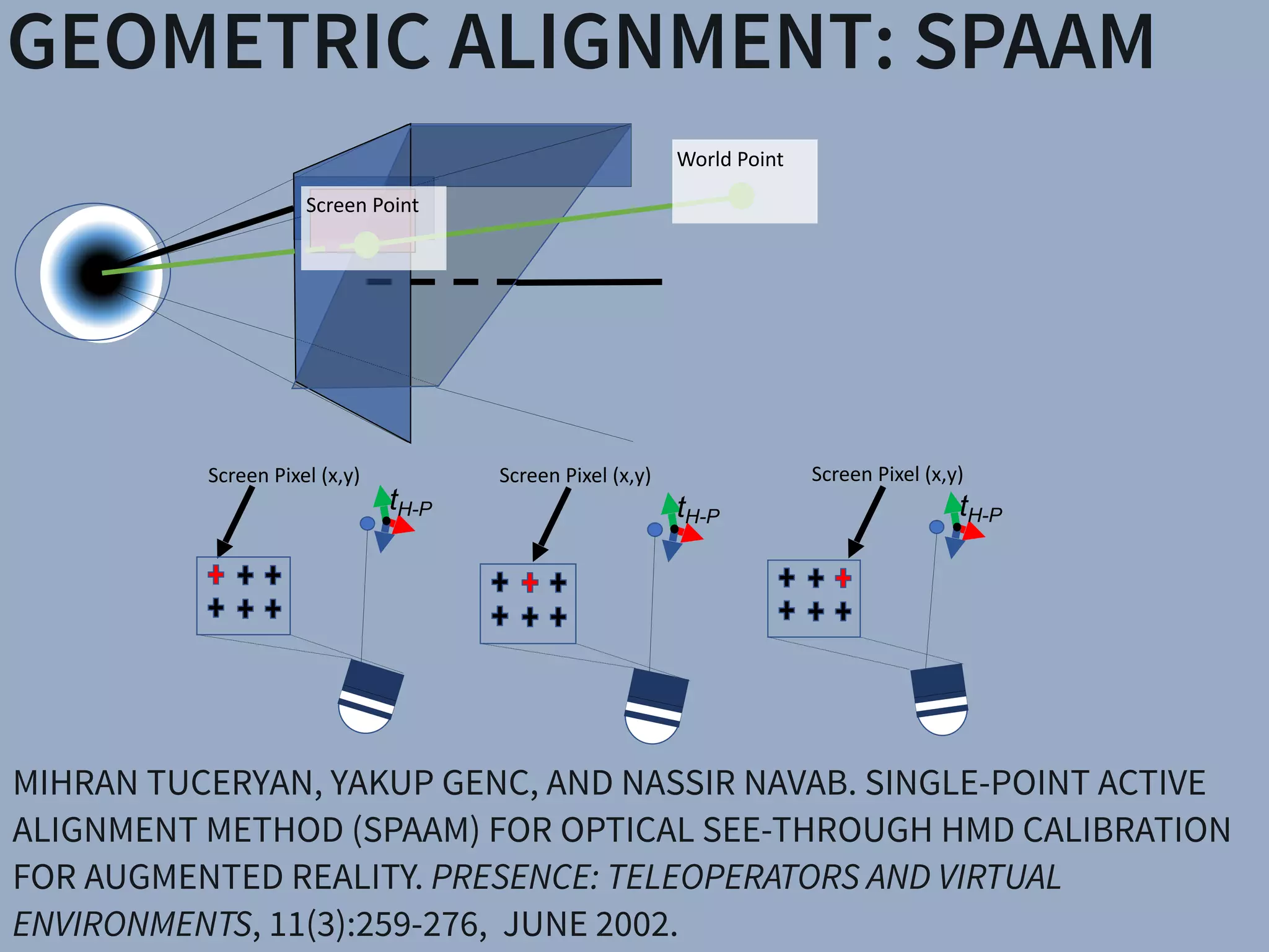
GEOMETRIC ALIGNMENT: SPAAM
MIHRAN TUCERYAN, YAKUP GENC, AND NASSIR NAVAB. SINGLE-POINT ACTIVE
ALIGNMENT METHOD (SPAAM) FOR OPTICAL SEE-THROUGH HMD CALIBRATION
FOR AUGMENTED REALITY. PRESENCE: TELEOPERATORS AND VIRTUAL
ENVIRONMENTS, 11(3):259-276, JUNE 2002.
Screen	Point
World	Point
tH-P
Screen	Pixel	(x,y)	
tH-P
Screen	Pixel	(x,y)	
tH-P
Screen	Pixel	(x,y)
Fig. 9. Stages of the experimental procedure. Every subject performs
an initial SPAAM calibration followed by the recording of eye images
and performance of both tasks using the SPAAM results. The HMD is
removed and refit to the subject, eye images recorded once again, and
both tasks for one of the remaining conditions performed. The proce
ET AL.:MOSER SUBJ ECTIVE EVALUATION OF A SEMI-AUTOMATIC O
Algorithm
Qua 2.5
SPAAM DSPAAM INDICA SPAAM DSPAAM INDICA SPAAM DSPAAM INDICA
2.5
Fig. 10. Mean subjective quality values for each calibration method dur-
ing each task, normalized to a 1–4 scale with 1 denoting the lowest
quality and 4 the highest. The values shown are across subjects with
individual plots for the Pillars task as well as each grid of the Cubes task.
Cubes-V shows normalized quality for the vertical cubes grid. Cubes-H
shows normalized quality for the horizontal cubes grid. Means with the
same letter, within each plot, are not significantly different at p  0.05
(Ryan REGWQ post-hoc homogeneous subset test).
X (Left−Right) Error (cm), ± 1 SEM
Z(Front−Back)Error(cm),±1SEM
−3
−2
−1
0
−1 0 1
●
SPAAM
Pillars
−1 0 1
●
DSPAAM
Pillars
−1 0 1
−3
−2
−1
0
●
INDICA
Pillars
A"
B"B"
Fig. 11. Mean Pillars task error along the X (Left-Right) and Z (Front-
Back) direction relative to the tracking coordinate frame. 0 indicates
no error. Error is reported as a distance value, with every 4 cm of er-
ror equating to a 1 pillar location difference in the respective direction.
Means with the same letter are not significantly different at p  0.05
(Ryan REGWQ post-hoc homogeneous subset test).
X (Left−Right) Error (cm)
Y(Up−Down)Err
−3
−2
−1 0 1
●
●
B"B"
Fig. 12. Mean vertical cubes grid task er
and X (Left-Right) direction relative to the
0 indicates no error. Error in each directio
value, with every 2 cm of error equating
difference in the respective direction. Mean
significantly different at p  0.05 (Ryan REG
subset test).
X (Left−Right) Error (cm)
Z(Front−Back)Error(cm),±1SEM
−5
−4
−3
−2
−1 0 1
●
SPAAM
Cubes−H
−1 0
●
DSPAAM
Cubes−H
B"
B"
Fig. 13. Mean horizontal cubes grid task er
and X (Left-Right) direction relative to the
0 indicates no error. Error in each directio
Fig. 1. Experimental hardware and design. (a) Display and camera system. (b) Task layout. (c) Pillars task. (
Abstract— With the growing availability of optical see-through (OST) head-mounted displays (HMDs), ther
robust, uncomplicated, and automatic calibration methods suited for non-expert users. This work presents th
which both objectively and subjectively examines registration accuracy produced by three OST HMD calibratio
(2) Degraded SPAAM, and (3) Recycled INDICA, a recently developed semi-automatic calibration method.
for evaluation include subject provided quality values and error between perceived and absolute registration c
show all three calibration methods produce very accurate registration in the horizontal direction but caused
distance of virtual objects to be closer than intended. Surprisingly, the semi-automatic calibration method p
registration vertically and in perceived object distance overall. User assessed quality values were also th
INDICA, particularly when objects were shown at distance. The results of this study confirm that Recycle
producing equal or superior on-screen registration compared to common OST HMD calibration methods. We
hazard in using reprojection error as a quantitative analysis technique to predict registration accuracy. We c
the further need for examining INDICA calibration in binocular HMD systems, and the present possibility for c
continuous calibration method for OST Augmented Reality.
Index Terms—Calibration, user study, OST HMD, INDICA, SPAAM, eye tracking
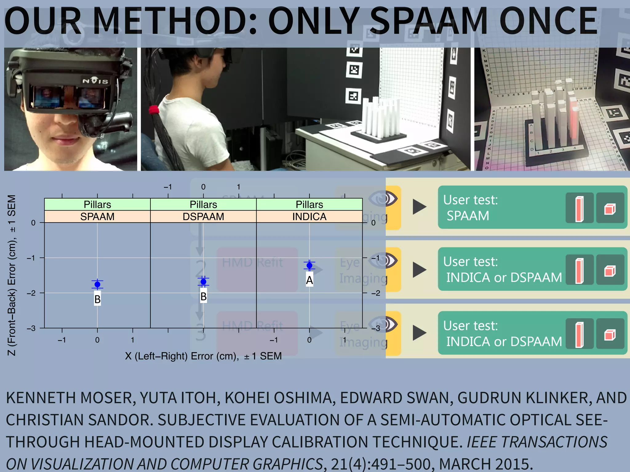
KENNETH MOSER, YUTA ITOH, KOHEI OSHIMA, EDWARD SWAN, GUDRUN KLINKER, AND
CHRISTIAN SANDOR. SUBJECTIVE EVALUATION OF A SEMI-AUTOMATIC OPTICAL SEE-
THROUGH HEAD-MOUNTED DISPLAY CALIBRATION TECHNIQUE. IEEE TRANSACTIONS
ON VISUALIZATION AND COMPUTER GRAPHICS, 21(4):491–500, MARCH 2015.
OUR METHOD: ONLY SPAAM ONCE
DESIRED MOST DISPLAYS
BLUR ARTIFACTS
BLUR ARTIFACTS
DESIRED MOST DISPLAYS
ved Clarity of Defocused Content on O
hrough Head-Mounted Displays
r⇤ ‡ Damien Constantine Rompapas† J. Edward Swa
Takafumi Taketomi† Christian Sandor† Hirokazu K
y
ogy
‡Computer Science & Engineering
Mississippi State University
§Mobile Computing L
Ritsumeikan Univ
(b) (c)
ect of focus blur in Optical See-Through (OST) Head-Mounted Displa
used in our study. (b) Simplified schematic of an OST AR system. B
viewed at unequal focal distances. (c), (d), (e): Views through an O
ausing the virtual image (d) to appear blurred; (e) an improved virtua
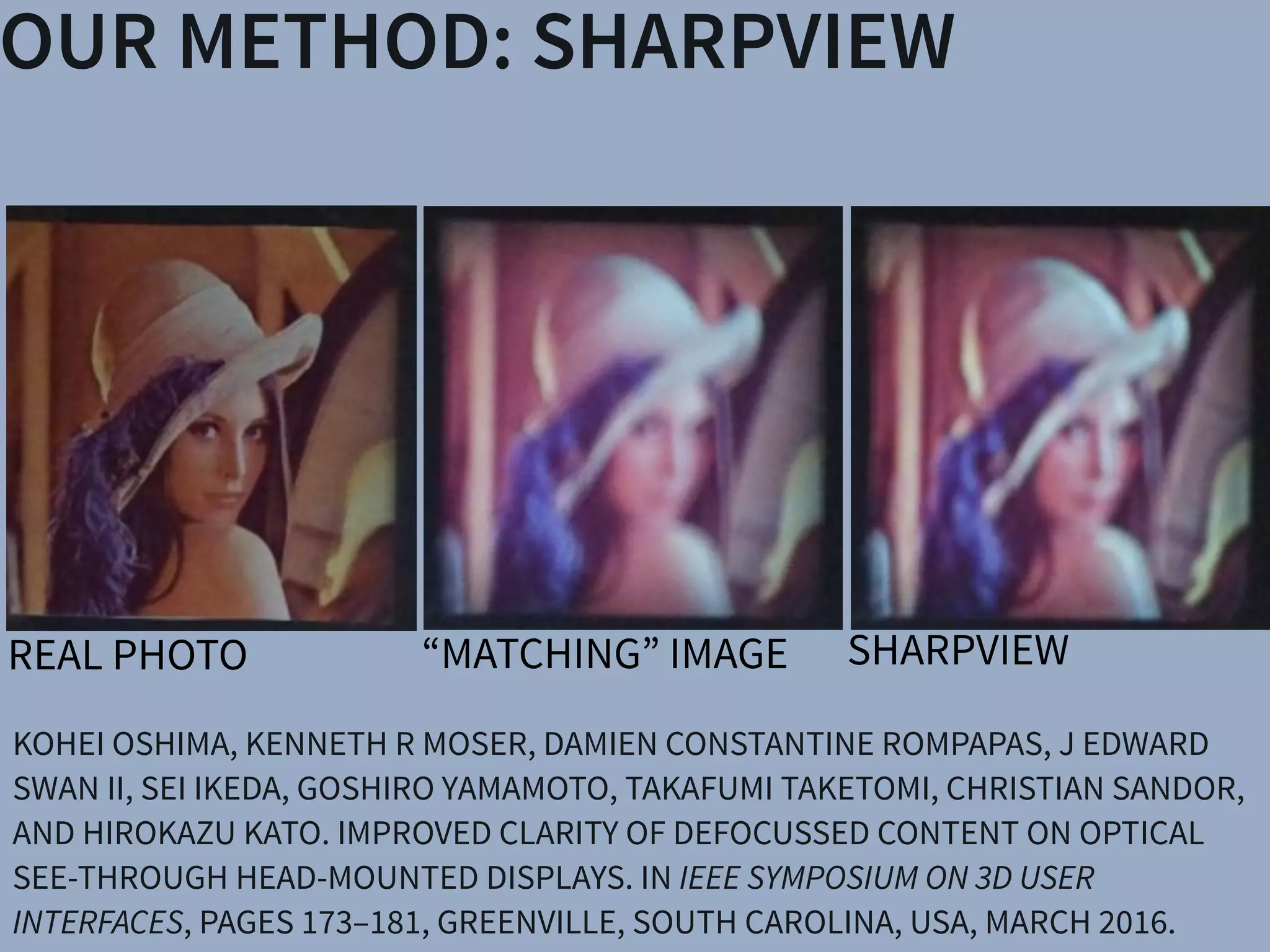
REAL PHOTO
“MATCHING” IMAGE
Christian Sandor Hirokazu Kato
& Engineering
e University
§Mobile Computing Laboratory
Ritsumeikan University
(c) (d) (e)
Head-Mounted Display (HMD) systems. (a) A user wearing the OST
an OST AR system. Blurring occurs when the virtual display screen
): Views through an OST Augmented Reality system, where the real
(e) an improved virtual image after application of SharpView.
KOHEI OSHIMA, KENNETH R MOSER, DAMIEN CONSTANTINE ROMPAPAS, J EDWARD
SWAN II, SEI IKEDA, GOSHIRO YAMAMOTO, TAKAFUMI TAKETOMI, CHRISTIAN SANDOR,
AND HIROKAZU KATO. IMPROVED CLARITY OF DEFOCUSSED CONTENT ON OPTICAL
SEE-THROUGH HEAD-MOUNTED DISPLAYS. IN IEEE SYMPOSIUM ON 3D USER
INTERFACES, PAGES 173–181, GREENVILLE, SOUTH CAROLINA, USA, MARCH 2016.
OUR METHOD: SHARPVIEW
SHARPVIEWREAL PHOTO
& Engineering
University
§Mobile Computing Laboratory
Ritsumeikan University
(c) (d) (e)
Head-Mounted Display (HMD) systems. (a) A user wearing the OST
an OST AR system. Blurring occurs when the virtual display screen
: Views through an OST Augmented Reality system, where the rea
(e) an improved virtual image after application of SharpView.
& Engineering
University
§Mobile Computing Laboratory
Ritsumeikan University
(c) (d) (e)
Head-Mounted Display (HMD) systems. (a) A user wearing the O
an OST AR system. Blurring occurs when the virtual display scre
: Views through an OST Augmented Reality system, where the r
& Engineering
University
§Mobile Computing Laboratory
Ritsumeikan University
(c) (d) (e)
Head-Mounted Display (HMD) systems. (a) A user wearing the OST
an OST AR system. Blurring occurs when the virtual display screen
: Views through an OST Augmented Reality system, where the rea
(e) an improved virtual image after application of SharpView.
“MATCHING” IMAGE
BASIC IDEA: PRE-SHARPENING
VISUALIZATION OF PSF
HTTPS://BENEDIKT-BITTERLI.ME/FEMTO.HTML
ESTIMATING EYE PSF
ng the Wiener filter, adjusted
o rendered images O and dis-
to the HMD.
P
|C|2
(4)
ocus blur, caused by accom-
play screen and world in OST
mined at run-time. We accom-
ssian function to approximate
te rates but with a reduction in
y modeling the intensity of the
screen, intersecting varying
ment of the pupil advisable. Additional system complexity m
Figure 2: Optical system formed by the user’s eye and an OST HM
The imaging plane corresponds to the user’s retina and the lens ap
ture to the user’s pupil.
expressed as sd, the ratio between the eye’s image p
is expressed as follows.
s : sd = v : u0
Here, sd is directly obtainable from equations (6) a
sd =
a
2
(1
u0
u
)
where a is pupil diameter, u is distance from the
world gaze point, and u0 represents the distance fro
image plane. When performing the actual convolut
filter and screen image, generally, sd may be con
ina. The intensity distribution, p, can be repre-
owing function.
P(x,y) =
1
2ps2
exp(
x2 +y2
2s2
) (5)
Gaussian function
!
SimplifiedGaussian functionto approximate the
decreasesprocessingtime allowingfasterupdate
OUR EXPERIMENTtion.
(a) (b)
Figure 5: Location of subjects relative to reference images placed at
25 cm (a) and 500 cm (b) from the subjects’ eyes.
capable of presenting stereo imagery at 60Hz with a maximum res-
olution of 960⇥540 per eye. The focal distance of the display was
both independently measured and confirmed by the manufacturer
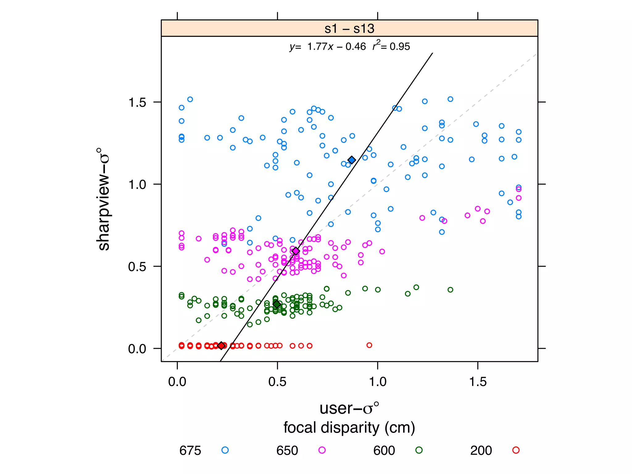
user−σ°
sharpview−σ°
0.0
0.5
1.0
1.5
0.0 0.5 1.0 1.5
●●
● ●
●
●
●
●
●
●
●
●
●
●
● ●
● ●●
●● ●● ●
●
●
●
●
●
●
●
●
●●
●●
●
●
●
●
● ●
●
●
●●
●●
●●
●
●
● ●
●
●
●
●
● ●
●●
●
●
●
●
●
●
●
●
●
●
●
●
●
●
●
●
●●
●
●
●
●
●
●
●●
●
● ●●
●
●
●●
●
●
●
●
●
●
●
●
●
●
● ●
● ●
●●
● ●●
●
●●
● ●
●● ● ●●●
●●
●
●
●
●
●●
●
●
●
●
●
●● ● ● ●
●
●
● ● ●
●● ●
●● ●
● ●●
●
●
●
●
●
● ●
●
●●
●
●
●
●
●
●
●●
● ●
●●
●
●
●
●
●
●
●
●
●
● ●
●
●
●
●
●
●
●●
●
● ●● ●●
● ●●
●● ● ● ●● ●
●
● ●● ●
●● ● ●
●●● ●● ●● ●●●● ●●
●
●●
●● ●●●
●● ●
● ● ●● ●●
● ●
● ●●● ●●●●●
●●●
●
● ● ●
●
● ●
● ● ●● ●●● ●●●●● ●●● ●●●●● ●●● ●● ●●● ●● ●● ● ●● ●●
● ●●●●● ●●● ●●●● ●● ●●●●●●●●● ●● ● ●● ●● ● ●●● ●● ● ●● ●●●● ● ●●● ●● ●● ●●● ●● ●●●● ●● ●●● ●● ●● ●● ● ●● ● ●● ●●●● ●● ●● ● ● ●●● ●●●●● ●● ● ● ●●● ●
y= 1.77x − 0.46 r2
= 0.95
s1 − s13
focal disparity (cm)
675 650 600 200● ● ● ●
subj
eled
ity l
and
ican
650c
W
of o
s.
ure
the
are
tend
tion
our
pres
T
data
disp
indi
rate
pari
it is
rate
MATCHING BLUR: REAL & VIRTUAL
DAMIEN CONSTANTINE ROMPAPAS, AITOR ROVIRA, SEI IKEDA, ALEXANDER
PLOPSKI, TAKAFUMI TAKETOMI, CHRISTIAN SANDOR, AND HIROKAZU KATO.
EYEAR: REFOCUSABLE AUGMENTED REALITY CONTENT THROUGH EYE
MEASUREMENTS. DEMO AT IEEE INTERNATIONAL SYMPOSIUM ON MIXED AND
AUGMENTED REALITY, MERIDA, MEXICO, SEPTEMBER 2016. BEST DEMO AWARD
users can focus their eyes on any part of the scene, and the CG will always reflect th
of the user’s eye (See Figure 1.7 for an example).
Figure 1.5: Example of a user looking into the box enclosure. Left: Without EyeA
can observe the DoF mismatch between CG (white hat) and real scene (dragon).
With EyeAR, the CG’s DoF accurately matches the natural DoF of the real scene.
Because EyeAR is able to create accurate DoF images on OST-HMD display, al
HMDs should include this functionality. However, the applications of EyeAR a
limited to creating indistinguishable AR content as our system directly measures t
For example, Sharpview (Oshima et al., 2015) sharpens content displayed on the
by approximating the user’s eye point spread function based on the user’s eye pu
Typical AR on OST-HMD scene with the user focusing on the objects in
r objects in front there is a DoF mismatch between CG (hat) and real scene
ghlighted with the white circle.
1
OUR DISPLAYMOST DISPLAYS
MATCHING BLUR: REAL & VIRTUAL
CONCEPT OF EYEAR
Measure Eye
- pupil size

- focal length
Render DOF Image
(Realtime Pathtracing
with NVIDIA Optix)
Correct Image Depth
Difference
(SharpView)
Display Result
OUR FIRST AR TURING TEST
0.40.50.60.70.8
Virtual Pillar
Correctguesses(%)
Green (0.25m) Blue (0.375m) Red (0.5m)
Autorefractometer
on
off
Figure 7: Overall percentage of correct guesses
for each pillar when the autorefractometer was on
(red line) and off (blue line). text in figure too
small. some text crossing boundaries
12 PARTICIPANTS
12 GUESSES
VIRTUAL
REAL
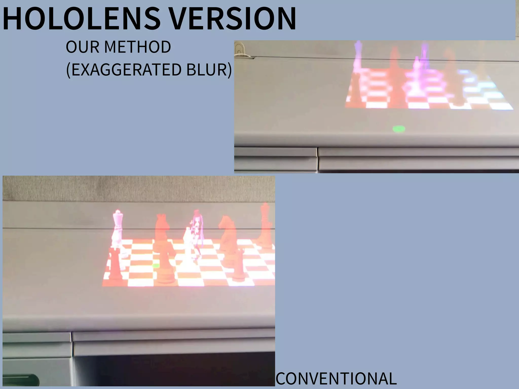
HOLOLENS VERSION
OUR METHOD
(EXAGGERATED BLUR)
CONVENTIONAL
DISPLAYSSharpView: Improved Clarity of Defocused C
See-Through Head-Mounted Dis
Kohei Oshima⇤ † Kenneth R Moser⇤ ‡ Damien Constantine Rompapas†
Goshiro Yamamoto† Takafumi Taketomi† Christian San
†Interactive Media Design Laboratory
Nara Institute of Science and Technology
‡Computer Science & Engineering
Mississippi State University
(a) (b) (c)
Figure 1: The cause and effect of focus blur in Optical See-Through (OST) Head-Mounted Displa
HMD and related hardware used in our study. (b) Simplified schematic of an OST AR system. B
and real world imagery are viewed at unequal focal distances. (c), (d), (e): Views through an O
world image (c) is in focus, causing the virtual image (d) to appear blurred; (e) an improved virtua
SharpView: Improved Clarity of Defocused Content on Optical
See-Through Head-Mounted Displays
Kohei Oshima⇤ † Kenneth R Moser⇤ ‡ Damien Constantine Rompapas† J. Edward Swan II‡ Sei Ikeda§
Goshiro Yamamoto† Takafumi Taketomi† Christian Sandor† Hirokazu Kato†
†Interactive Media Design Laboratory
Nara Institute of Science and Technology
‡Computer Science & Engineering
Mississippi State University
§Mobile Computing Laboratory
Ritsumeikan University
(a) (b) (c) (d) (e)
Figure 1: The cause and effect of focus blur in Optical See-Through (OST) Head-Mounted Display (HMD) systems. (a) A user wearing the OST
HMD and related hardware used in our study. (b) Simplified schematic of an OST AR system. Blurring occurs when the virtual display screen
and real world imagery are viewed at unequal focal distances. (c), (d), (e): Views through an OST Augmented Reality system, where the real
world image (c) is in focus, causing the virtual image (d) to appear blurred; (e) an improved virtual image after application of SharpView.
ABSTRACT
Augmented Reality (AR) systems, which utilize optical see-through
head-mounted displays, are becoming more common place, with
several consumer level options already available, and the promise of
additional, more advanced, devices on the horizon. A common fac-
tor among current generation optical see-through devices, though,
is fixed focal distance to virtual content. While fixed focus is not a
concern for video see-through AR, since both virtual and real world
imagery are combined into a single image by the display, unequal
distances between real world objects and the virtual display screen
in optical see-through AR is unavoidable.
In this work, we investigate the issue of focus blur, in particular,
the blurring caused by simultaneously viewing virtual content and
physical objects in the environment at differing focal distances. We
Multimedia Information Systems—Artificial, augmented, and vir-
tual realities; I.4.4 [Image Processing and Computer Vision]:
Restoration—Wiener filtering
1 INTRODUCTION
Optical See-Through (OST) Head-Mounted Displays (HMDs) have
seen an increase in both popularity and accessibility with the re-
lease of several consumer level options, including Google Glass
and Epson Moverio BT-200, and announced future offerings, such
as Microsoft’s HoloLens, on the horizon. The transparent display
technology used in these HMDs affords a unique experience, allow-
ing the user to view on-screen computer generated (CG) content
while maintaining a direct view of their environment, a property
extremely well suited for augmented reality (AR) systems. Un-
arpView: Improved Clarity of Defocused Content on Optical
See-Through Head-Mounted Displays
ma⇤ † Kenneth R Moser⇤ ‡ Damien Constantine Rompapas† J. Edward Swan II‡ Sei Ikeda§
Goshiro Yamamoto† Takafumi Taketomi† Christian Sandor† Hirokazu Kato†
active Media Design Laboratory
stitute of Science and Technology
‡Computer Science & Engineering
Mississippi State University
§Mobile Computing Laboratory
Ritsumeikan University
(b) (c) (d) (e)
use and effect of focus blur in Optical See-Through (OST) Head-Mounted Display (HMD) systems. (a) A user wearing the OST
hardware used in our study. (b) Simplified schematic of an OST AR system. Blurring occurs when the virtual display screen
magery are viewed at unequal focal distances. (c), (d), (e): Views through an OST Augmented Reality system, where the real
s in focus, causing the virtual image (d) to appear blurred; (e) an improved virtual image after application of SharpView.
ity (AR) systems, which utilize optical see-through
isplays, are becoming more common place, with
r level options already available, and the promise of
advanced, devices on the horizon. A common fac-
nt generation optical see-through devices, though,
Multimedia Information Systems—Artificial, augmented, and vir-
tual realities; I.4.4 [Image Processing and Computer Vision]:
Restoration—Wiener filtering
1 INTRODUCTION
Optical See-Through (OST) Head-Mounted Displays (HMDs) have
n of a Semi-Automatic Optical See-Through
nted Display Calibration Technique
E, Yuta Itoh, Student Member, IEEE, Kohei Oshima, Student Member, IEEE,
E, Gudrun Klinker, Member, IEEE, and Christian Sandor, Member, IEEE
. (a) Display and camera system. (b) Task layout. (c) Pillars task. (d) Cubes task.
of optical see-through (OST) head-mounted displays (HMDs), there is a present need for
bration methods suited for non-expert users. This work presents the results of a user study
mines registration accuracy produced by three OST HMD calibration methods: (1) SPAAM,
NDICA, a recently developed semi-automatic calibration method. Accuracy metrics used
ality values and error between perceived and absolute registration coordinates. Our results
e very accurate registration in the horizontal direction but caused subjects to perceive the
EEE TRANSACTIONS ON VISUALIZATION AND COMPUTER GRAPHICS, VOL. 21, NO. ,4 APRIL2015
PHILOSOPHY: TRUE AUGMENTED REALITY
There have been a number of shape displays based on pin
architecture. The FEELEX project [14] was one of the early
attempts to design combined shapes and computer graphics
displays that can be explored by touch. FEELEX consisted
of several mechanical pistons actuated by motors and cov-
ered by a soft silicon surface. The images were projected
onto its surface and synchronized with the movement of the
pistons, creating simple shapes.
Lumen [32] is a low resolution, 13 by 13-pixel, bit-map
display where each pixel can also physically move up and
down (Figure 4). The resulting display can present both 2D
graphic images and moving physical shapes that can be
observed, touched, and felt with the hands. The 2D position
Figure 2.7: Hand-fixed reference frame: Augmentations move
example shows a user discussing a virtual map wit
map from di↵erent angles, he can pick it up from t
his belt and put it in his hand.
TEDX ADELAIDE 2010
DEMO ONLY: HTTPS://WWW.YOUTUBE.COM/WATCH?V=3MEALLE8KZS
FULL TALK: HTTP://WWW.YOUTUBE.COM/ WATCH?V=U2YE2LHULWA

SLIDES: HTTP://WWW.SLIDESHARE.NET/CHRISTIANSANDOR/TEDX10-SANDOR
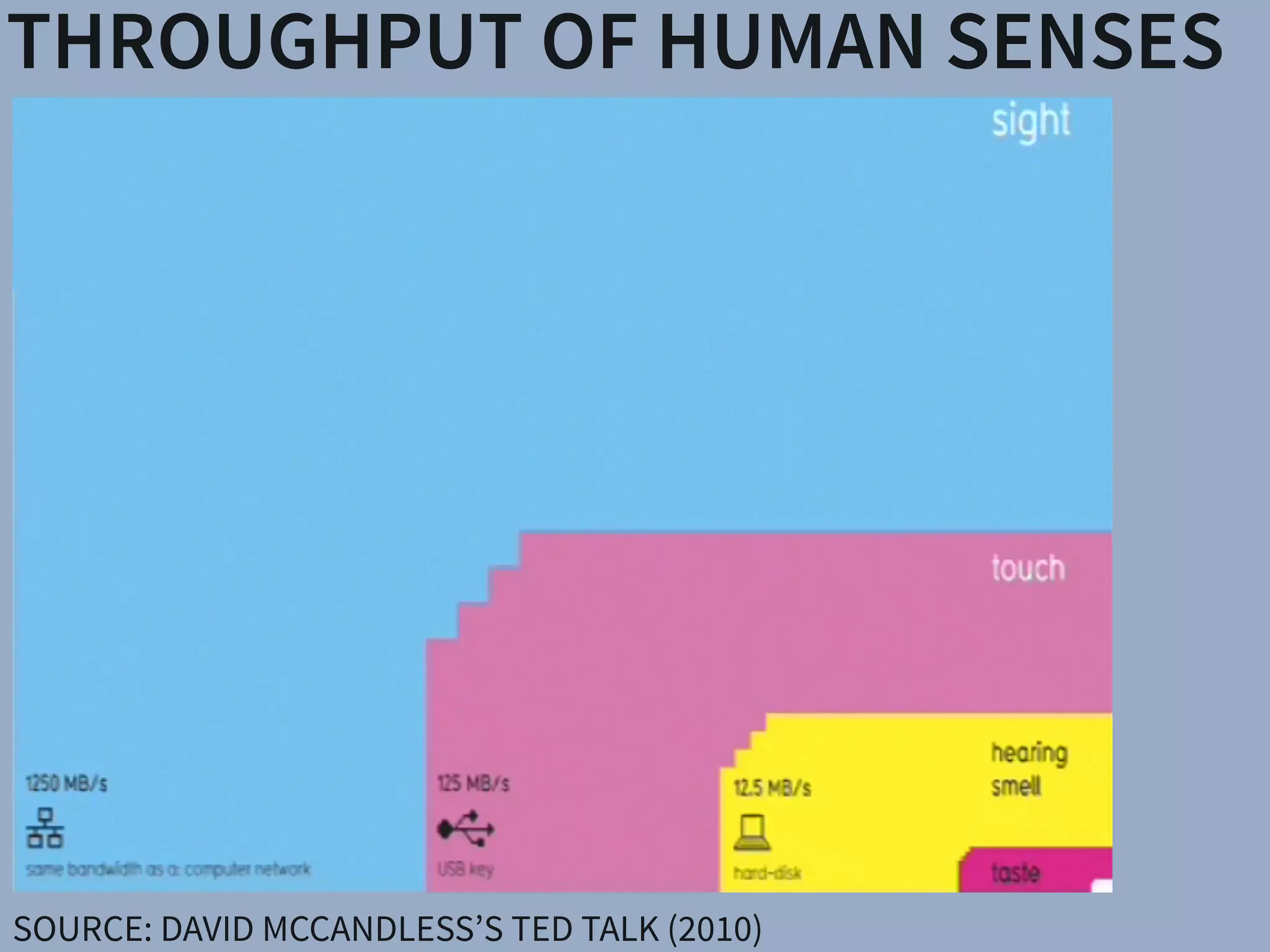
THROUGHPUT OF HUMAN SENSES
SOURCE: DAVID MCCANDLESS’S TED TALK (2010)
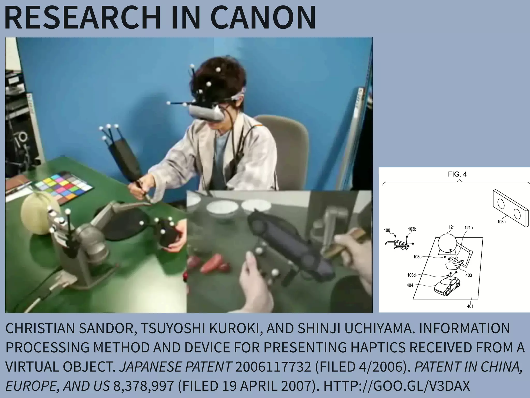
RESEARCH IN CANON
CHRISTIAN SANDOR, TSUYOSHI KUROKI, AND SHINJI UCHIYAMA. INFORMATION
PROCESSING METHOD AND DEVICE FOR PRESENTING HAPTICS RECEIVED FROM A
VIRTUAL OBJECT. JAPANESE PATENT 2006117732 (FILED 4/2006). PATENT IN CHINA,
EUROPE, AND US 8,378,997 (FILED 19 APRIL 2007). HTTP://GOO.GL/V3DAX
RESEARCH IN CANON
CHRISTIAN SANDOR, SHINJI UCHIYAMA, AND HIROYUKI YAMAMOTO. VISUO-
HAPTIC SYSTEMS: HALF-MIRRORS CONSIDERED HARMFUL. IN PROCEEDINGS OF
THE IEEE WORLD HAPTICS CONFERENCE, PAGES 292–297. IEEE, MARCH 2007.
TSUKUBA, JAPAN.
LARGE SCALE HAPTICS DISPLAY AT
NAIST (UNPUBLISHED)
DISPLAYS APPLICATIONSSharpView: Improved Clarity of Defocused C
See-Through Head-Mounted Dis
Kohei Oshima⇤ † Kenneth R Moser⇤ ‡ Damien Constantine Rompapas†
Goshiro Yamamoto† Takafumi Taketomi† Christian San
†Interactive Media Design Laboratory
Nara Institute of Science and Technology
‡Computer Science & Engineering
Mississippi State University
(a) (b) (c)
Figure 1: The cause and effect of focus blur in Optical See-Through (OST) Head-Mounted Displa
HMD and related hardware used in our study. (b) Simplified schematic of an OST AR system. B
and real world imagery are viewed at unequal focal distances. (c), (d), (e): Views through an O
world image (c) is in focus, causing the virtual image (d) to appear blurred; (e) an improved virtua
SharpView: Improved Clarity of Defocused Content on Optical
See-Through Head-Mounted Displays
Kohei Oshima⇤ † Kenneth R Moser⇤ ‡ Damien Constantine Rompapas† J. Edward Swan II‡ Sei Ikeda§
Goshiro Yamamoto† Takafumi Taketomi† Christian Sandor† Hirokazu Kato†
†Interactive Media Design Laboratory
Nara Institute of Science and Technology
‡Computer Science & Engineering
Mississippi State University
§Mobile Computing Laboratory
Ritsumeikan University
(a) (b) (c) (d) (e)
Figure 1: The cause and effect of focus blur in Optical See-Through (OST) Head-Mounted Display (HMD) systems. (a) A user wearing the OST
HMD and related hardware used in our study. (b) Simplified schematic of an OST AR system. Blurring occurs when the virtual display screen
and real world imagery are viewed at unequal focal distances. (c), (d), (e): Views through an OST Augmented Reality system, where the real
world image (c) is in focus, causing the virtual image (d) to appear blurred; (e) an improved virtual image after application of SharpView.
ABSTRACT
Augmented Reality (AR) systems, which utilize optical see-through
head-mounted displays, are becoming more common place, with
several consumer level options already available, and the promise of
additional, more advanced, devices on the horizon. A common fac-
tor among current generation optical see-through devices, though,
is fixed focal distance to virtual content. While fixed focus is not a
concern for video see-through AR, since both virtual and real world
imagery are combined into a single image by the display, unequal
distances between real world objects and the virtual display screen
in optical see-through AR is unavoidable.
In this work, we investigate the issue of focus blur, in particular,
the blurring caused by simultaneously viewing virtual content and
physical objects in the environment at differing focal distances. We
Multimedia Information Systems—Artificial, augmented, and vir-
tual realities; I.4.4 [Image Processing and Computer Vision]:
Restoration—Wiener filtering
1 INTRODUCTION
Optical See-Through (OST) Head-Mounted Displays (HMDs) have
seen an increase in both popularity and accessibility with the re-
lease of several consumer level options, including Google Glass
and Epson Moverio BT-200, and announced future offerings, such
as Microsoft’s HoloLens, on the horizon. The transparent display
technology used in these HMDs affords a unique experience, allow-
ing the user to view on-screen computer generated (CG) content
while maintaining a direct view of their environment, a property
extremely well suited for augmented reality (AR) systems. Un-
arpView: Improved Clarity of Defocused Content on Optical
See-Through Head-Mounted Displays
ma⇤ † Kenneth R Moser⇤ ‡ Damien Constantine Rompapas† J. Edward Swan II‡ Sei Ikeda§
Goshiro Yamamoto† Takafumi Taketomi† Christian Sandor† Hirokazu Kato†
active Media Design Laboratory
stitute of Science and Technology
‡Computer Science & Engineering
Mississippi State University
§Mobile Computing Laboratory
Ritsumeikan University
(b) (c) (d) (e)
use and effect of focus blur in Optical See-Through (OST) Head-Mounted Display (HMD) systems. (a) A user wearing the OST
hardware used in our study. (b) Simplified schematic of an OST AR system. Blurring occurs when the virtual display screen
magery are viewed at unequal focal distances. (c), (d), (e): Views through an OST Augmented Reality system, where the real
s in focus, causing the virtual image (d) to appear blurred; (e) an improved virtual image after application of SharpView.
ity (AR) systems, which utilize optical see-through
isplays, are becoming more common place, with
r level options already available, and the promise of
advanced, devices on the horizon. A common fac-
nt generation optical see-through devices, though,
Multimedia Information Systems—Artificial, augmented, and vir-
tual realities; I.4.4 [Image Processing and Computer Vision]:
Restoration—Wiener filtering
1 INTRODUCTION
Optical See-Through (OST) Head-Mounted Displays (HMDs) have
n of a Semi-Automatic Optical See-Through
nted Display Calibration Technique
E, Yuta Itoh, Student Member, IEEE, Kohei Oshima, Student Member, IEEE,
E, Gudrun Klinker, Member, IEEE, and Christian Sandor, Member, IEEE
. (a) Display and camera system. (b) Task layout. (c) Pillars task. (d) Cubes task.
of optical see-through (OST) head-mounted displays (HMDs), there is a present need for
bration methods suited for non-expert users. This work presents the results of a user study
mines registration accuracy produced by three OST HMD calibration methods: (1) SPAAM,
NDICA, a recently developed semi-automatic calibration method. Accuracy metrics used
ality values and error between perceived and absolute registration coordinates. Our results
e very accurate registration in the horizontal direction but caused subjects to perceive the
EEE TRANSACTIONS ON VISUALIZATION AND COMPUTER GRAPHICS, VOL. 21, NO. ,4 APRIL2015
PHILOSOPHY: TRUE AUGMENTED REALITY
There have been a number of shape displays based on pin
architecture. The FEELEX project [14] was one of the early
attempts to design combined shapes and computer graphics
displays that can be explored by touch. FEELEX consisted
of several mechanical pistons actuated by motors and cov-
ered by a soft silicon surface. The images were projected
onto its surface and synchronized with the movement of the
pistons, creating simple shapes.
Lumen [32] is a low resolution, 13 by 13-pixel, bit-map
display where each pixel can also physically move up and
down (Figure 4). The resulting display can present both 2D
graphic images and moving physical shapes that can be
observed, touched, and felt with the hands. The 2D position
Figure 2.7: Hand-fixed reference frame: Augmentations move
example shows a user discussing a virtual map wit
map from di↵erent angles, he can pick it up from t
his belt and put it in his hand.
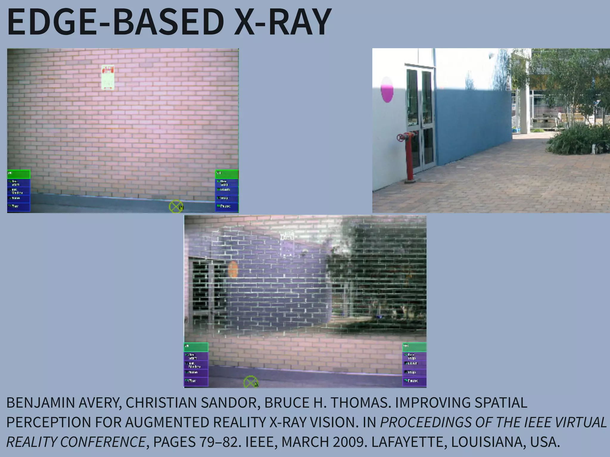
EDGE-BASED X-RAY
BENJAMIN AVERY, CHRISTIAN SANDOR, BRUCE H. THOMAS. IMPROVING SPATIAL
PERCEPTION FOR AUGMENTED REALITY X-RAY VISION. IN PROCEEDINGS OF THE IEEE VIRTUAL
REALITY CONFERENCE, PAGES 79–82. IEEE, MARCH 2009. LAFAYETTE, LOUISIANA, USA.
SALIENCY X-RAY
CHRISTIAN SANDOR, ANDREW CUNNINGHAM, ARINDAM DEY, AND VILLE-VEIKKO
MATTILA. AN AUGMENTED REALITY X-RAY SYSTEM BASED ON VISUAL SALIENCY. IN
PROCEEDINGS OF THE IEEE INTERNATIONAL SYMPOSIUM ON MIXED AND
AUGMENTED REALITY, PAGES 27–36, SEOUL, KOREA, OCTOBER 2010.
SALIENCY X-RAY
CHRISTIAN SANDOR, ANDREW CUNNINGHAM, AND MATTILA VILLE-VEIKKO.
METHOD AND APPARATUS FOR AN AUGMENTED REALITY X-RAY. US PATENT
APPLICATION 12/785,170 (FILED 21 MAY 2010). HTTP://GOO.GL/NCVZJ
MELTING
CHRISTIAN SANDOR, ANDREW CUNNINGHAM, ULRICH ECK, DONALD URQUHART, GRAEME JARVIS,
ARINDAM DEY, SEBASTIEN BARBIER, MICHAEL R. MARNER, SANG RHEE. EGOCENTRIC SPACE-DISTORTING
VISUALIZATIONS FOR RAPID ENVIRONMENT EXPLORATION IN MOBILE MIXED REALITY. IN PROCEEDINGS
OF THE IEEE VIRTUAL REALITY CONFERENCE, PAGES 47–50, WALTHAM, MA, USA, MARCH 2010.
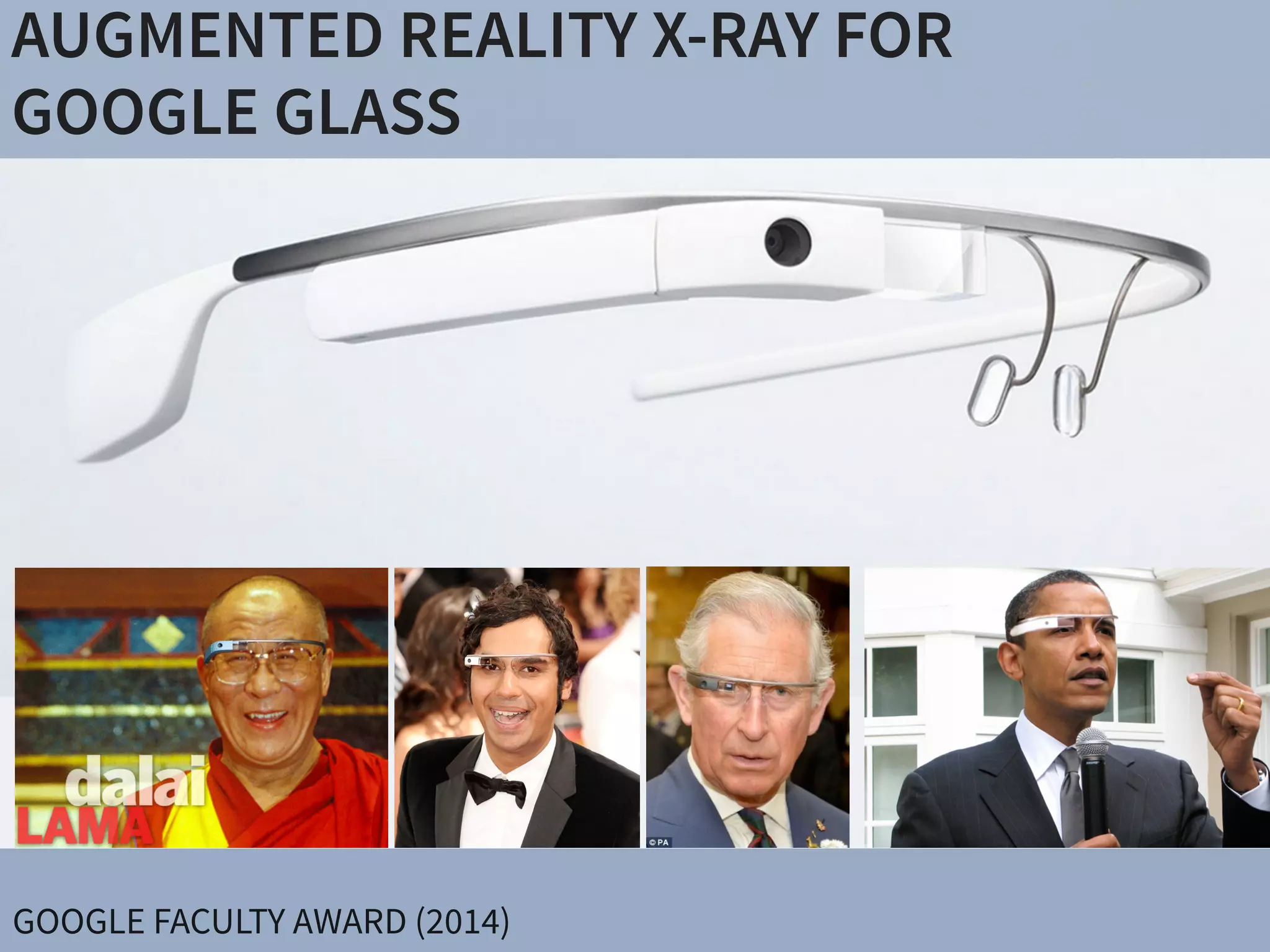
AUGMENTED REALITY X-RAY FOR 

GOOGLE GLASS
GOOGLE FACULTY AWARD (2014)
DEMO AT SIGGRAPH ASIA (12/2014)
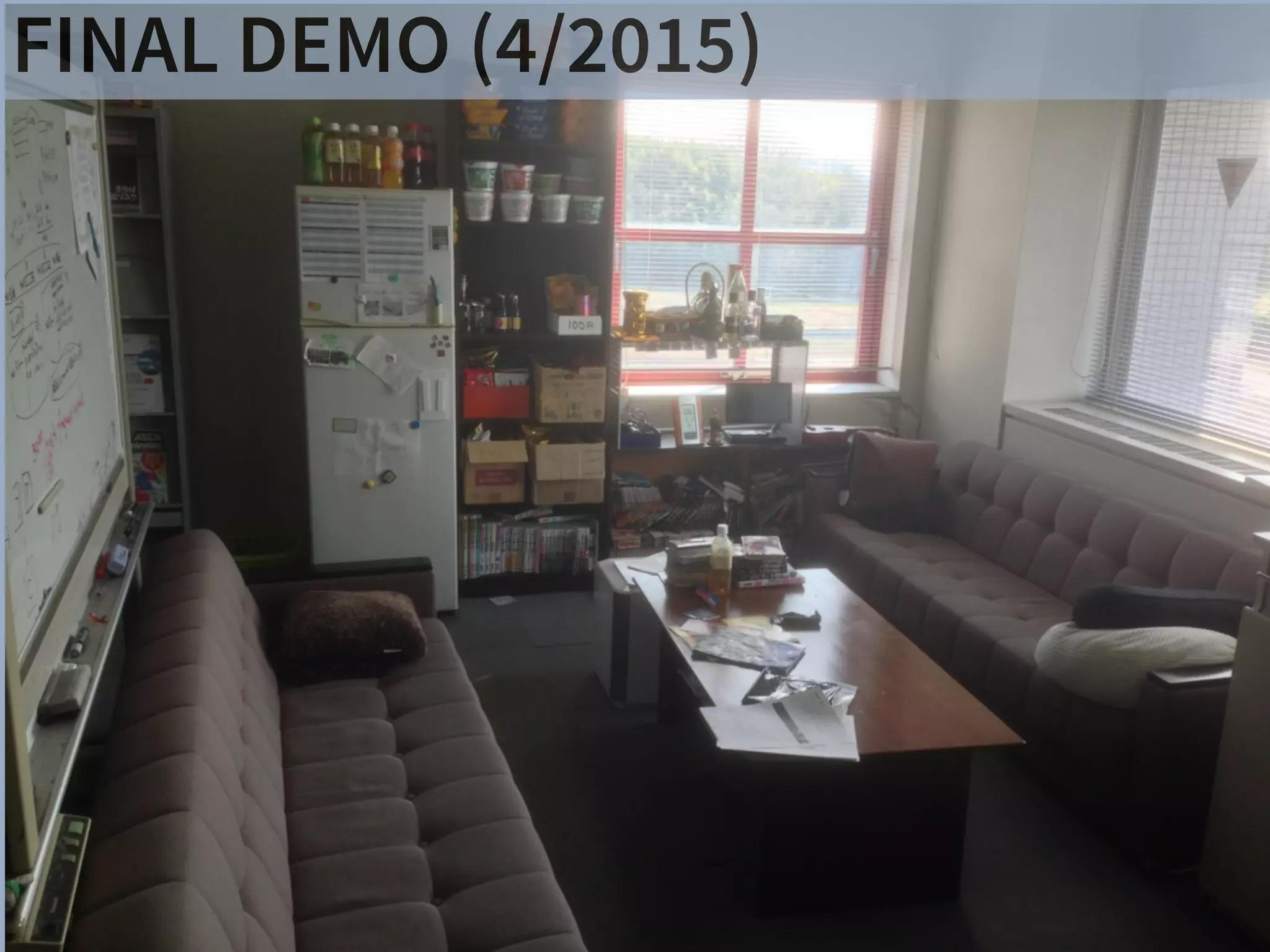
FINAL DEMO (4/2015)
FINAL DEMO (4/2015)
Rehabilitation & Sports Medicine
Frozen Shoulder
SHOULDER - 26
Range of Motion Exercises:
Pendulum (Circular)
Let arm move in a circle
clockwise, then counter-
clockwise, by rocking body
weight in a circular pattern.
Repeat 10 times.
Do 3-5 sessions per day.
SHOULDER - 7
Range of Motion Exercises
(Self-Stretching Activities):
Flexion
Sitting upright, slide forearm
forward along table, bending
from waist until a stretch is
felt. Hold 30 seconds.
Repeat 1-4 times
Do 1 session per day.
SHOULDER - 11
Range of Motion Exercises
(Self-Stretching Activities):
External Rotation (alternate)
Keep palm of hand against
door frame, and elbow bent at
90°. Turn body from fixed
hand until a stretch is felt.
Hold 30 seconds.
Repeat 1-4 times
Do 1 session per day.
SHOULDER - 9
Range of Motion Exercises (Self-
Stretching Activities): Abduction
With arm resting on table, palm up, bring
head down toward arm and simultaneously
move trunk away from table. Hold 30
seconds.
Repeat 1-4 times Do 1 session per day.
SHOULDER - 73
Towel Stretch for Internal
Rotation
Pull involved arm up
behind back by pulling
towel upward with other
arm. Hold 30 seconds.
Repeat 1-4 times
Do 1 session per day.
SCAP SETS
Pull your shoulders back,
pinching the shoulder
blades together. Do not let
the shoulders come
forward. Hold 5-10
seconds.
Repeat 10 times
Do 1 session per day.
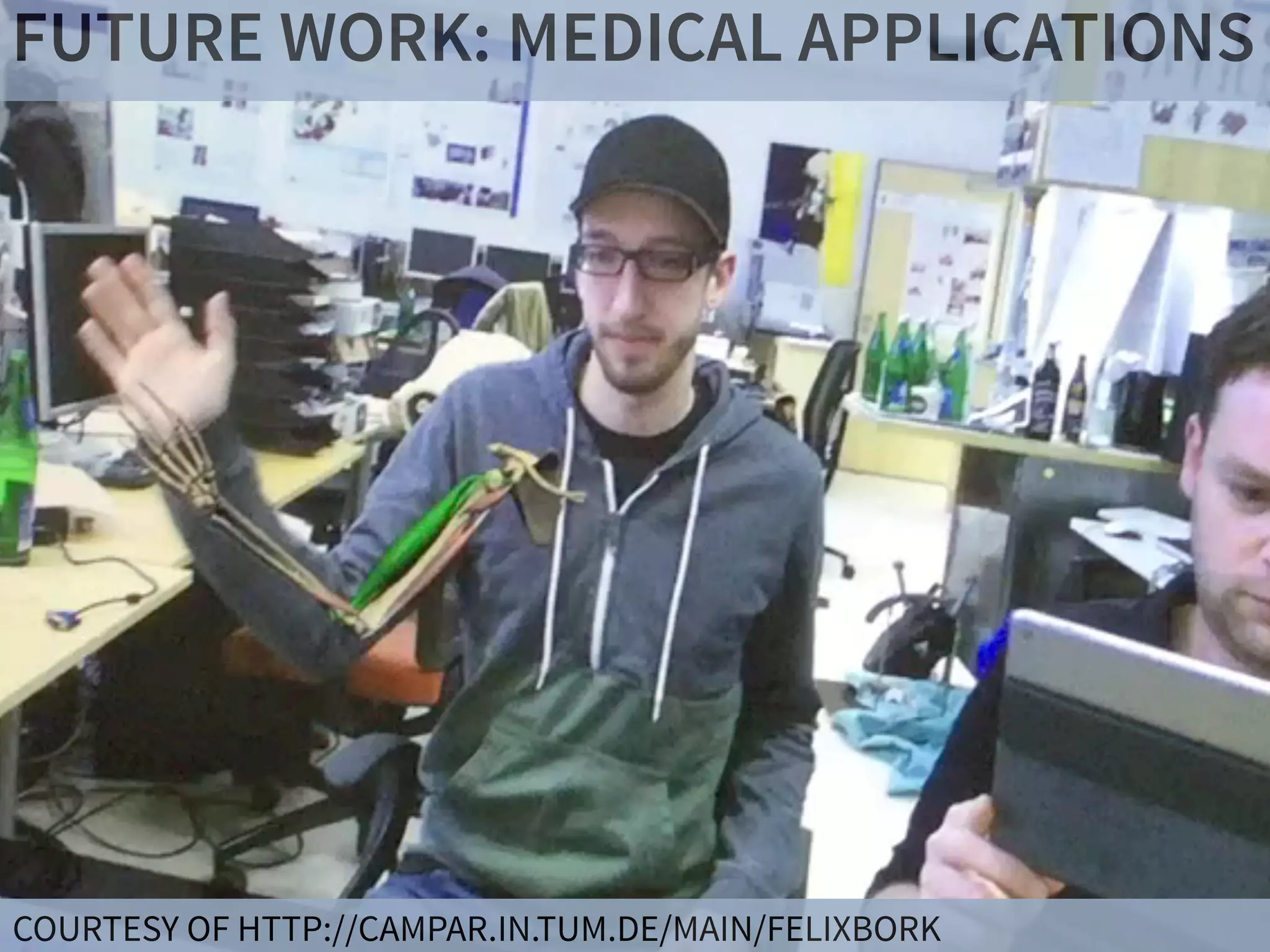
FUTURE WORK: MEDICAL APPLICATIONS
COURTESY OF HTTP://CAMPAR.IN.TUM.DE/MAIN/FELIXBORK
DISPLAYS APPLICATIONSSharpView: Improved Clarity of Defocused C
See-Through Head-Mounted Dis
Kohei Oshima⇤ † Kenneth R Moser⇤ ‡ Damien Constantine Rompapas†
Goshiro Yamamoto† Takafumi Taketomi† Christian San
†Interactive Media Design Laboratory
Nara Institute of Science and Technology
‡Computer Science & Engineering
Mississippi State University
(a) (b) (c)
Figure 1: The cause and effect of focus blur in Optical See-Through (OST) Head-Mounted Displa
HMD and related hardware used in our study. (b) Simplified schematic of an OST AR system. B
and real world imagery are viewed at unequal focal distances. (c), (d), (e): Views through an O
world image (c) is in focus, causing the virtual image (d) to appear blurred; (e) an improved virtua
SharpView: Improved Clarity of Defocused Content on Optical
See-Through Head-Mounted Displays
Kohei Oshima⇤ † Kenneth R Moser⇤ ‡ Damien Constantine Rompapas† J. Edward Swan II‡ Sei Ikeda§
Goshiro Yamamoto† Takafumi Taketomi† Christian Sandor† Hirokazu Kato†
†Interactive Media Design Laboratory
Nara Institute of Science and Technology
‡Computer Science & Engineering
Mississippi State University
§Mobile Computing Laboratory
Ritsumeikan University
(a) (b) (c) (d) (e)
Figure 1: The cause and effect of focus blur in Optical See-Through (OST) Head-Mounted Display (HMD) systems. (a) A user wearing the OST
HMD and related hardware used in our study. (b) Simplified schematic of an OST AR system. Blurring occurs when the virtual display screen
and real world imagery are viewed at unequal focal distances. (c), (d), (e): Views through an OST Augmented Reality system, where the real
world image (c) is in focus, causing the virtual image (d) to appear blurred; (e) an improved virtual image after application of SharpView.
ABSTRACT
Augmented Reality (AR) systems, which utilize optical see-through
head-mounted displays, are becoming more common place, with
several consumer level options already available, and the promise of
additional, more advanced, devices on the horizon. A common fac-
tor among current generation optical see-through devices, though,
is fixed focal distance to virtual content. While fixed focus is not a
concern for video see-through AR, since both virtual and real world
imagery are combined into a single image by the display, unequal
distances between real world objects and the virtual display screen
in optical see-through AR is unavoidable.
In this work, we investigate the issue of focus blur, in particular,
the blurring caused by simultaneously viewing virtual content and
physical objects in the environment at differing focal distances. We
Multimedia Information Systems—Artificial, augmented, and vir-
tual realities; I.4.4 [Image Processing and Computer Vision]:
Restoration—Wiener filtering
1 INTRODUCTION
Optical See-Through (OST) Head-Mounted Displays (HMDs) have
seen an increase in both popularity and accessibility with the re-
lease of several consumer level options, including Google Glass
and Epson Moverio BT-200, and announced future offerings, such
as Microsoft’s HoloLens, on the horizon. The transparent display
technology used in these HMDs affords a unique experience, allow-
ing the user to view on-screen computer generated (CG) content
while maintaining a direct view of their environment, a property
extremely well suited for augmented reality (AR) systems. Un-
arpView: Improved Clarity of Defocused Content on Optical
See-Through Head-Mounted Displays
ma⇤ † Kenneth R Moser⇤ ‡ Damien Constantine Rompapas† J. Edward Swan II‡ Sei Ikeda§
Goshiro Yamamoto† Takafumi Taketomi† Christian Sandor† Hirokazu Kato†
active Media Design Laboratory
stitute of Science and Technology
‡Computer Science & Engineering
Mississippi State University
§Mobile Computing Laboratory
Ritsumeikan University
(b) (c) (d) (e)
use and effect of focus blur in Optical See-Through (OST) Head-Mounted Display (HMD) systems. (a) A user wearing the OST
hardware used in our study. (b) Simplified schematic of an OST AR system. Blurring occurs when the virtual display screen
magery are viewed at unequal focal distances. (c), (d), (e): Views through an OST Augmented Reality system, where the real
s in focus, causing the virtual image (d) to appear blurred; (e) an improved virtual image after application of SharpView.
ity (AR) systems, which utilize optical see-through
isplays, are becoming more common place, with
r level options already available, and the promise of
advanced, devices on the horizon. A common fac-
nt generation optical see-through devices, though,
Multimedia Information Systems—Artificial, augmented, and vir-
tual realities; I.4.4 [Image Processing and Computer Vision]:
Restoration—Wiener filtering
1 INTRODUCTION
Optical See-Through (OST) Head-Mounted Displays (HMDs) have
n of a Semi-Automatic Optical See-Through
nted Display Calibration Technique
E, Yuta Itoh, Student Member, IEEE, Kohei Oshima, Student Member, IEEE,
E, Gudrun Klinker, Member, IEEE, and Christian Sandor, Member, IEEE
. (a) Display and camera system. (b) Task layout. (c) Pillars task. (d) Cubes task.
of optical see-through (OST) head-mounted displays (HMDs), there is a present need for
bration methods suited for non-expert users. This work presents the results of a user study
mines registration accuracy produced by three OST HMD calibration methods: (1) SPAAM,
NDICA, a recently developed semi-automatic calibration method. Accuracy metrics used
ality values and error between perceived and absolute registration coordinates. Our results
e very accurate registration in the horizontal direction but caused subjects to perceive the
EEE TRANSACTIONS ON VISUALIZATION AND COMPUTER GRAPHICS, VOL. 21, NO. ,4 APRIL2015
PHILOSOPHY: TRUE AUGMENTED REALITY
There have been a number of shape displays based on pin
architecture. The FEELEX project [14] was one of the early
attempts to design combined shapes and computer graphics
displays that can be explored by touch. FEELEX consisted
of several mechanical pistons actuated by motors and cov-
ered by a soft silicon surface. The images were projected
onto its surface and synchronized with the movement of the
pistons, creating simple shapes.
Lumen [32] is a low resolution, 13 by 13-pixel, bit-map
display where each pixel can also physically move up and
down (Figure 4). The resulting display can present both 2D
graphic images and moving physical shapes that can be
observed, touched, and felt with the hands. The 2D position
Figure 2.7: Hand-fixed reference frame: Augmentations move
example shows a user discussing a virtual map wit
map from di↵erent angles, he can pick it up from t
his belt and put it in his hand.
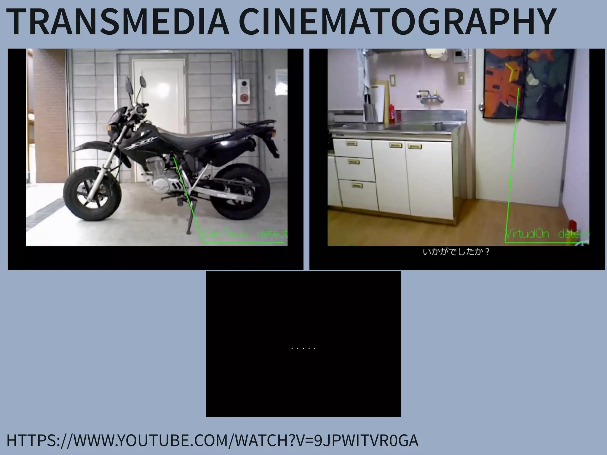
TRANSMEDIA CINEMATOGRAPHY
HTTPS://WWW.YOUTUBE.COM/WATCH?V=9JPWITVR0GA
Nurikabe Kappa
Tengu
Long neck woman
Big centipede
Mokumokuren
Nopperabou
Tsuchigumo
Nurarihyon
Paper umbrella haunted
Umibouzu
Gasyadokuro
YŌKAI
AR YŌKAI(UNPUBLISHED)
Big centipede
Nurikabe
Mokumokuren
PHILOSOPHY: TRUE AUGMENTED REALITY
There have been a number of shape displays based on pin
architecture. The FEELEX project [14] was one of the early
attempts to design combined shapes and computer graphics
displays that can be explored by touch. FEELEX consisted
of several mechanical pistons actuated by motors and cov-
ered by a soft silicon surface. The images were projected
onto its surface and synchronized with the movement of the
pistons, creating simple shapes.
Lumen [32] is a low resolution, 13 by 13-pixel, bit-map
display where each pixel can also physically move up and
down (Figure 4). The resulting display can present both 2D
graphic images and moving physical shapes that can be
observed, touched, and felt with the hands. The 2D position
Figure 2.7: Hand-fixed reference frame: Augmentations move
example shows a user discussing a virtual map wit
map from di↵erent angles, he can pick it up from t
his belt and put it in his hand.
DISPLAYS APPLICATIONSSharpView: Improved Clarity of Defocused C
See-Through Head-Mounted Dis
Kohei Oshima⇤ † Kenneth R Moser⇤ ‡ Damien Constantine Rompapas†
Goshiro Yamamoto† Takafumi Taketomi† Christian San
†Interactive Media Design Laboratory
Nara Institute of Science and Technology
‡Computer Science & Engineering
Mississippi State University
(a) (b) (c)
Figure 1: The cause and effect of focus blur in Optical See-Through (OST) Head-Mounted Displa
HMD and related hardware used in our study. (b) Simplified schematic of an OST AR system. B
and real world imagery are viewed at unequal focal distances. (c), (d), (e): Views through an O
world image (c) is in focus, causing the virtual image (d) to appear blurred; (e) an improved virtua
SharpView: Improved Clarity of Defocused Content on Optical
See-Through Head-Mounted Displays
Kohei Oshima⇤ † Kenneth R Moser⇤ ‡ Damien Constantine Rompapas† J. Edward Swan II‡ Sei Ikeda§
Goshiro Yamamoto† Takafumi Taketomi† Christian Sandor† Hirokazu Kato†
†Interactive Media Design Laboratory
Nara Institute of Science and Technology
‡Computer Science & Engineering
Mississippi State University
§Mobile Computing Laboratory
Ritsumeikan University
(a) (b) (c) (d) (e)
Figure 1: The cause and effect of focus blur in Optical See-Through (OST) Head-Mounted Display (HMD) systems. (a) A user wearing the OST
HMD and related hardware used in our study. (b) Simplified schematic of an OST AR system. Blurring occurs when the virtual display screen
and real world imagery are viewed at unequal focal distances. (c), (d), (e): Views through an OST Augmented Reality system, where the real
world image (c) is in focus, causing the virtual image (d) to appear blurred; (e) an improved virtual image after application of SharpView.
ABSTRACT
Augmented Reality (AR) systems, which utilize optical see-through
head-mounted displays, are becoming more common place, with
several consumer level options already available, and the promise of
additional, more advanced, devices on the horizon. A common fac-
tor among current generation optical see-through devices, though,
is fixed focal distance to virtual content. While fixed focus is not a
concern for video see-through AR, since both virtual and real world
imagery are combined into a single image by the display, unequal
distances between real world objects and the virtual display screen
in optical see-through AR is unavoidable.
In this work, we investigate the issue of focus blur, in particular,
the blurring caused by simultaneously viewing virtual content and
physical objects in the environment at differing focal distances. We
Multimedia Information Systems—Artificial, augmented, and vir-
tual realities; I.4.4 [Image Processing and Computer Vision]:
Restoration—Wiener filtering
1 INTRODUCTION
Optical See-Through (OST) Head-Mounted Displays (HMDs) have
seen an increase in both popularity and accessibility with the re-
lease of several consumer level options, including Google Glass
and Epson Moverio BT-200, and announced future offerings, such
as Microsoft’s HoloLens, on the horizon. The transparent display
technology used in these HMDs affords a unique experience, allow-
ing the user to view on-screen computer generated (CG) content
while maintaining a direct view of their environment, a property
extremely well suited for augmented reality (AR) systems. Un-
arpView: Improved Clarity of Defocused Content on Optical
See-Through Head-Mounted Displays
ma⇤ † Kenneth R Moser⇤ ‡ Damien Constantine Rompapas† J. Edward Swan II‡ Sei Ikeda§
Goshiro Yamamoto† Takafumi Taketomi† Christian Sandor† Hirokazu Kato†
active Media Design Laboratory
stitute of Science and Technology
‡Computer Science & Engineering
Mississippi State University
§Mobile Computing Laboratory
Ritsumeikan University
(b) (c) (d) (e)
use and effect of focus blur in Optical See-Through (OST) Head-Mounted Display (HMD) systems. (a) A user wearing the OST
hardware used in our study. (b) Simplified schematic of an OST AR system. Blurring occurs when the virtual display screen
magery are viewed at unequal focal distances. (c), (d), (e): Views through an OST Augmented Reality system, where the real
s in focus, causing the virtual image (d) to appear blurred; (e) an improved virtual image after application of SharpView.
ity (AR) systems, which utilize optical see-through
isplays, are becoming more common place, with
r level options already available, and the promise of
advanced, devices on the horizon. A common fac-
nt generation optical see-through devices, though,
Multimedia Information Systems—Artificial, augmented, and vir-
tual realities; I.4.4 [Image Processing and Computer Vision]:
Restoration—Wiener filtering
1 INTRODUCTION
Optical See-Through (OST) Head-Mounted Displays (HMDs) have
n of a Semi-Automatic Optical See-Through
nted Display Calibration Technique
E, Yuta Itoh, Student Member, IEEE, Kohei Oshima, Student Member, IEEE,
E, Gudrun Klinker, Member, IEEE, and Christian Sandor, Member, IEEE
. (a) Display and camera system. (b) Task layout. (c) Pillars task. (d) Cubes task.
of optical see-through (OST) head-mounted displays (HMDs), there is a present need for
bration methods suited for non-expert users. This work presents the results of a user study
mines registration accuracy produced by three OST HMD calibration methods: (1) SPAAM,
NDICA, a recently developed semi-automatic calibration method. Accuracy metrics used
ality values and error between perceived and absolute registration coordinates. Our results
e very accurate registration in the horizontal direction but caused subjects to perceive the
EEE TRANSACTIONS ON VISUALIZATION AND COMPUTER GRAPHICS, VOL. 21, NO. ,4 APRIL2015CONCLUSIONS
SUMMARY
AR: EXTREMELY HIGH POTENTIAL (UNLIKE VR) 

INTERDISCIPLINARY: COMPUTER GRAPHICS, COMPUTER VISION,
OPTICS, PERCEPTION RESEARCH
REQUEST
CHAT TO ME AT IDW! LOOKING FOR GOOD COLLABORATORS
CHRISTIAN@SANDOR.COM

SLIDES WILL BE ONLINE WITHIN ONE HOUR! 

HTTP://WWW.SLIDESHARE.NET/CHRISTIANSANDOR

More Related Content

What's hot

Digital Image Processing: Image Colors
Digital Image Processing: Image ColorsDigital Image Processing: Image Colors
Digital Image Processing: Image ColorsBasra University, Iraq
 
Land Cover Feature Extraction using Hybrid Swarm Intelligence Techniques - A ...
Land Cover Feature Extraction using Hybrid Swarm Intelligence Techniques - A ...Land Cover Feature Extraction using Hybrid Swarm Intelligence Techniques - A ...
Land Cover Feature Extraction using Hybrid Swarm Intelligence Techniques - A ...IDES Editor
 
Chapter 1 and 2 gonzalez and woods
Chapter 1 and 2 gonzalez and woodsChapter 1 and 2 gonzalez and woods
Chapter 1 and 2 gonzalez and woodsasodariyabhavesh
 
DIGITAL IMAGE PROCESSING - LECTURE NOTES
DIGITAL IMAGE PROCESSING - LECTURE NOTESDIGITAL IMAGE PROCESSING - LECTURE NOTES
DIGITAL IMAGE PROCESSING - LECTURE NOTESEzhilya venkat
 
Studying interaction with 3D mobile maps
Studying interaction with 3D mobile mapsStudying interaction with 3D mobile maps
Studying interaction with 3D mobile mapsAalto University
 
Robust content based watermarking algorithm using singular value decompositio...
Robust content based watermarking algorithm using singular value decompositio...Robust content based watermarking algorithm using singular value decompositio...
Robust content based watermarking algorithm using singular value decompositio...sipij
 
Gaining Colour Stability in Live Image Capturing
Gaining Colour Stability in Live Image CapturingGaining Colour Stability in Live Image Capturing
Gaining Colour Stability in Live Image CapturingGuy K. Kloss
 
Availability of Mobile Augmented Reality System for Urban Landscape Simulation
Availability of Mobile Augmented Reality System for Urban Landscape SimulationAvailability of Mobile Augmented Reality System for Urban Landscape Simulation
Availability of Mobile Augmented Reality System for Urban Landscape SimulationTomohiro Fukuda
 
Mapping virtual and physical reality
Mapping virtual and physical realityMapping virtual and physical reality
Mapping virtual and physical realityChheang Vuthea
 
Neural Scene Representation & Rendering: Introduction to Novel View Synthesis
Neural Scene Representation & Rendering: Introduction to Novel View SynthesisNeural Scene Representation & Rendering: Introduction to Novel View Synthesis
Neural Scene Representation & Rendering: Introduction to Novel View SynthesisVincent Sitzmann
 
IRJET- Photo Restoration using Multiresolution Texture Synthesis and Convolut...
IRJET- Photo Restoration using Multiresolution Texture Synthesis and Convolut...IRJET- Photo Restoration using Multiresolution Texture Synthesis and Convolut...
IRJET- Photo Restoration using Multiresolution Texture Synthesis and Convolut...IRJET Journal
 
Human Depth Perception
Human Depth PerceptionHuman Depth Perception
Human Depth PerceptionIJARIIT
 
A Practical and Robust Bump-mapping Technique for Today’s GPUs (paper)
A Practical and Robust Bump-mapping Technique for Today’s GPUs (paper)A Practical and Robust Bump-mapping Technique for Today’s GPUs (paper)
A Practical and Robust Bump-mapping Technique for Today’s GPUs (paper)Mark Kilgard
 
Focused Image Creation Algorithms for digital holography
Focused Image Creation Algorithms for digital holographyFocused Image Creation Algorithms for digital holography
Focused Image Creation Algorithms for digital holographyConor Mc Elhinney
 
Literature study article
Literature study articleLiterature study article
Literature study articleakaspers
 
Digital image processing question bank
Digital image processing question bankDigital image processing question bank
Digital image processing question bankYaseen Albakry
 
DISTRIBUTED AND SYNCHRONISED VR MEETING USING CLOUD COMPUTING: Availability a...
DISTRIBUTED AND SYNCHRONISED VR MEETING USING CLOUD COMPUTING: Availability a...DISTRIBUTED AND SYNCHRONISED VR MEETING USING CLOUD COMPUTING: Availability a...
DISTRIBUTED AND SYNCHRONISED VR MEETING USING CLOUD COMPUTING: Availability a...Tomohiro Fukuda
 

What's hot (20)

Report
ReportReport
Report
 
Digital Image Processing: Image Colors
Digital Image Processing: Image ColorsDigital Image Processing: Image Colors
Digital Image Processing: Image Colors
 
Land Cover Feature Extraction using Hybrid Swarm Intelligence Techniques - A ...
Land Cover Feature Extraction using Hybrid Swarm Intelligence Techniques - A ...Land Cover Feature Extraction using Hybrid Swarm Intelligence Techniques - A ...
Land Cover Feature Extraction using Hybrid Swarm Intelligence Techniques - A ...
 
Chapter 1 and 2 gonzalez and woods
Chapter 1 and 2 gonzalez and woodsChapter 1 and 2 gonzalez and woods
Chapter 1 and 2 gonzalez and woods
 
DIGITAL IMAGE PROCESSING - LECTURE NOTES
DIGITAL IMAGE PROCESSING - LECTURE NOTESDIGITAL IMAGE PROCESSING - LECTURE NOTES
DIGITAL IMAGE PROCESSING - LECTURE NOTES
 
Studying interaction with 3D mobile maps
Studying interaction with 3D mobile mapsStudying interaction with 3D mobile maps
Studying interaction with 3D mobile maps
 
Robust content based watermarking algorithm using singular value decompositio...
Robust content based watermarking algorithm using singular value decompositio...Robust content based watermarking algorithm using singular value decompositio...
Robust content based watermarking algorithm using singular value decompositio...
 
Gaining Colour Stability in Live Image Capturing
Gaining Colour Stability in Live Image CapturingGaining Colour Stability in Live Image Capturing
Gaining Colour Stability in Live Image Capturing
 
Dip chapter 2
Dip chapter 2Dip chapter 2
Dip chapter 2
 
Availability of Mobile Augmented Reality System for Urban Landscape Simulation
Availability of Mobile Augmented Reality System for Urban Landscape SimulationAvailability of Mobile Augmented Reality System for Urban Landscape Simulation
Availability of Mobile Augmented Reality System for Urban Landscape Simulation
 
Mapping virtual and physical reality
Mapping virtual and physical realityMapping virtual and physical reality
Mapping virtual and physical reality
 
Neural Scene Representation & Rendering: Introduction to Novel View Synthesis
Neural Scene Representation & Rendering: Introduction to Novel View SynthesisNeural Scene Representation & Rendering: Introduction to Novel View Synthesis
Neural Scene Representation & Rendering: Introduction to Novel View Synthesis
 
IRJET- Photo Restoration using Multiresolution Texture Synthesis and Convolut...
IRJET- Photo Restoration using Multiresolution Texture Synthesis and Convolut...IRJET- Photo Restoration using Multiresolution Texture Synthesis and Convolut...
IRJET- Photo Restoration using Multiresolution Texture Synthesis and Convolut...
 
Human Depth Perception
Human Depth PerceptionHuman Depth Perception
Human Depth Perception
 
Light field
Light field Light field
Light field
 
A Practical and Robust Bump-mapping Technique for Today’s GPUs (paper)
A Practical and Robust Bump-mapping Technique for Today’s GPUs (paper)A Practical and Robust Bump-mapping Technique for Today’s GPUs (paper)
A Practical and Robust Bump-mapping Technique for Today’s GPUs (paper)
 
Focused Image Creation Algorithms for digital holography
Focused Image Creation Algorithms for digital holographyFocused Image Creation Algorithms for digital holography
Focused Image Creation Algorithms for digital holography
 
Literature study article
Literature study articleLiterature study article
Literature study article
 
Digital image processing question bank
Digital image processing question bankDigital image processing question bank
Digital image processing question bank
 
DISTRIBUTED AND SYNCHRONISED VR MEETING USING CLOUD COMPUTING: Availability a...
DISTRIBUTED AND SYNCHRONISED VR MEETING USING CLOUD COMPUTING: Availability a...DISTRIBUTED AND SYNCHRONISED VR MEETING USING CLOUD COMPUTING: Availability a...
DISTRIBUTED AND SYNCHRONISED VR MEETING USING CLOUD COMPUTING: Availability a...
 

Similar to Keynote at 23rd International Display Workshop

Keynote at VR in Science and Industry
Keynote at VR in Science and Industry Keynote at VR in Science and Industry
Keynote at VR in Science and Industry Christian Sandor
 
IRJET- Object Recognization from Structural Information using Perception
IRJET- Object Recognization from Structural Information using PerceptionIRJET- Object Recognization from Structural Information using Perception
IRJET- Object Recognization from Structural Information using PerceptionIRJET Journal
 
10.1109@ecs.2015.7124874
10.1109@ecs.2015.712487410.1109@ecs.2015.7124874
10.1109@ecs.2015.7124874Ganesh Raja
 
IT6005 digital image processing question bank
IT6005   digital image processing question bankIT6005   digital image processing question bank
IT6005 digital image processing question bankGayathri Krishnamoorthy
 
Visual hull construction from semitransparent coloured silhouettes
Visual hull construction from semitransparent coloured silhouettesVisual hull construction from semitransparent coloured silhouettes
Visual hull construction from semitransparent coloured silhouettesijcga
 
NUMBER PLATE IMAGE DETECTION FOR FAST MOTION VEHICLES USING BLUR KERNEL ESTIM...
NUMBER PLATE IMAGE DETECTION FOR FAST MOTION VEHICLES USING BLUR KERNEL ESTIM...NUMBER PLATE IMAGE DETECTION FOR FAST MOTION VEHICLES USING BLUR KERNEL ESTIM...
NUMBER PLATE IMAGE DETECTION FOR FAST MOTION VEHICLES USING BLUR KERNEL ESTIM...paperpublications3
 
Visual Hull Construction from Semitransparent Coloured Silhouettes
Visual Hull Construction from Semitransparent Coloured Silhouettes  Visual Hull Construction from Semitransparent Coloured Silhouettes
Visual Hull Construction from Semitransparent Coloured Silhouettes ijcga
 
Visual Hull Construction from Semitransparent Coloured Silhouettes
Visual Hull Construction from Semitransparent Coloured Silhouettes  Visual Hull Construction from Semitransparent Coloured Silhouettes
Visual Hull Construction from Semitransparent Coloured Silhouettes ijcga
 
Semantic Mapping of Road Scenes
Semantic Mapping of Road ScenesSemantic Mapping of Road Scenes
Semantic Mapping of Road ScenesSunando Sengupta
 
Eyeglasses-free Display: Towards Correcting Visual Aberrations with Computati...
Eyeglasses-free Display: Towards Correcting Visual Aberrations with Computati...Eyeglasses-free Display: Towards Correcting Visual Aberrations with Computati...
Eyeglasses-free Display: Towards Correcting Visual Aberrations with Computati...Dario Caliendo
 
Sig2014 vision correcting display
Sig2014 vision correcting displaySig2014 vision correcting display
Sig2014 vision correcting displayWael Sharba
 
Screenless displays seminar report
Screenless displays seminar reportScreenless displays seminar report
Screenless displays seminar reportJeevan Kumar D
 
Multiresolution SVD based Image Fusion
Multiresolution SVD based Image FusionMultiresolution SVD based Image Fusion
Multiresolution SVD based Image FusionIOSRJVSP
 
Heckbert p s__adaptive_radiosity_textures_for_bidirectional_r
Heckbert p s__adaptive_radiosity_textures_for_bidirectional_rHeckbert p s__adaptive_radiosity_textures_for_bidirectional_r
Heckbert p s__adaptive_radiosity_textures_for_bidirectional_rXavier Davias
 
A Study on Designing 7D Holography
A Study on Designing 7D HolographyA Study on Designing 7D Holography
A Study on Designing 7D Holographyijtsrd
 
Soft Shadow Rendering based on Real Light Source Estimation in Augmented Reality
Soft Shadow Rendering based on Real Light Source Estimation in Augmented RealitySoft Shadow Rendering based on Real Light Source Estimation in Augmented Reality
Soft Shadow Rendering based on Real Light Source Estimation in Augmented RealityWaqas Tariq
 
44328856-Augmented-Reality.ppt
44328856-Augmented-Reality.ppt44328856-Augmented-Reality.ppt
44328856-Augmented-Reality.pptAjayPoonia22
 
44328856-Augmented-Reality.ppt
44328856-Augmented-Reality.ppt44328856-Augmented-Reality.ppt
44328856-Augmented-Reality.pptNagulahimasri
 

Similar to Keynote at 23rd International Display Workshop (20)

Keynote at VR in Science and Industry
Keynote at VR in Science and Industry Keynote at VR in Science and Industry
Keynote at VR in Science and Industry
 
IRJET- Object Recognization from Structural Information using Perception
IRJET- Object Recognization from Structural Information using PerceptionIRJET- Object Recognization from Structural Information using Perception
IRJET- Object Recognization from Structural Information using Perception
 
Chapter2 DIP
Chapter2 DIP Chapter2 DIP
Chapter2 DIP
 
FinalReport
FinalReportFinalReport
FinalReport
 
10.1109@ecs.2015.7124874
10.1109@ecs.2015.712487410.1109@ecs.2015.7124874
10.1109@ecs.2015.7124874
 
IT6005 digital image processing question bank
IT6005   digital image processing question bankIT6005   digital image processing question bank
IT6005 digital image processing question bank
 
Visual hull construction from semitransparent coloured silhouettes
Visual hull construction from semitransparent coloured silhouettesVisual hull construction from semitransparent coloured silhouettes
Visual hull construction from semitransparent coloured silhouettes
 
NUMBER PLATE IMAGE DETECTION FOR FAST MOTION VEHICLES USING BLUR KERNEL ESTIM...
NUMBER PLATE IMAGE DETECTION FOR FAST MOTION VEHICLES USING BLUR KERNEL ESTIM...NUMBER PLATE IMAGE DETECTION FOR FAST MOTION VEHICLES USING BLUR KERNEL ESTIM...
NUMBER PLATE IMAGE DETECTION FOR FAST MOTION VEHICLES USING BLUR KERNEL ESTIM...
 
Visual Hull Construction from Semitransparent Coloured Silhouettes
Visual Hull Construction from Semitransparent Coloured Silhouettes  Visual Hull Construction from Semitransparent Coloured Silhouettes
Visual Hull Construction from Semitransparent Coloured Silhouettes
 
Visual Hull Construction from Semitransparent Coloured Silhouettes
Visual Hull Construction from Semitransparent Coloured Silhouettes  Visual Hull Construction from Semitransparent Coloured Silhouettes
Visual Hull Construction from Semitransparent Coloured Silhouettes
 
Semantic Mapping of Road Scenes
Semantic Mapping of Road ScenesSemantic Mapping of Road Scenes
Semantic Mapping of Road Scenes
 
Eyeglasses-free Display: Towards Correcting Visual Aberrations with Computati...
Eyeglasses-free Display: Towards Correcting Visual Aberrations with Computati...Eyeglasses-free Display: Towards Correcting Visual Aberrations with Computati...
Eyeglasses-free Display: Towards Correcting Visual Aberrations with Computati...
 
Sig2014 vision correcting display
Sig2014 vision correcting displaySig2014 vision correcting display
Sig2014 vision correcting display
 
Screenless displays seminar report
Screenless displays seminar reportScreenless displays seminar report
Screenless displays seminar report
 
Multiresolution SVD based Image Fusion
Multiresolution SVD based Image FusionMultiresolution SVD based Image Fusion
Multiresolution SVD based Image Fusion
 
Heckbert p s__adaptive_radiosity_textures_for_bidirectional_r
Heckbert p s__adaptive_radiosity_textures_for_bidirectional_rHeckbert p s__adaptive_radiosity_textures_for_bidirectional_r
Heckbert p s__adaptive_radiosity_textures_for_bidirectional_r
 
A Study on Designing 7D Holography
A Study on Designing 7D HolographyA Study on Designing 7D Holography
A Study on Designing 7D Holography
 
Soft Shadow Rendering based on Real Light Source Estimation in Augmented Reality
Soft Shadow Rendering based on Real Light Source Estimation in Augmented RealitySoft Shadow Rendering based on Real Light Source Estimation in Augmented Reality
Soft Shadow Rendering based on Real Light Source Estimation in Augmented Reality
 
44328856-Augmented-Reality.ppt
44328856-Augmented-Reality.ppt44328856-Augmented-Reality.ppt
44328856-Augmented-Reality.ppt
 
44328856-Augmented-Reality.ppt
44328856-Augmented-Reality.ppt44328856-Augmented-Reality.ppt
44328856-Augmented-Reality.ppt
 

Recently uploaded

Behavioral Disorder: Schizophrenia & it's Case Study.pdf
Behavioral Disorder: Schizophrenia & it's Case Study.pdfBehavioral Disorder: Schizophrenia & it's Case Study.pdf
Behavioral Disorder: Schizophrenia & it's Case Study.pdfSELF-EXPLANATORY
 
RESPIRATORY ADAPTATIONS TO HYPOXIA IN HUMNAS.pptx
RESPIRATORY ADAPTATIONS TO HYPOXIA IN HUMNAS.pptxRESPIRATORY ADAPTATIONS TO HYPOXIA IN HUMNAS.pptx
RESPIRATORY ADAPTATIONS TO HYPOXIA IN HUMNAS.pptxFarihaAbdulRasheed
 
OECD bibliometric indicators: Selected highlights, April 2024
OECD bibliometric indicators: Selected highlights, April 2024OECD bibliometric indicators: Selected highlights, April 2024
OECD bibliometric indicators: Selected highlights, April 2024innovationoecd
 
Call Girls In Nihal Vihar Delhi ❤️8860477959 Looking Escorts In 24/7 Delhi NCR
Call Girls In Nihal Vihar Delhi ❤️8860477959 Looking Escorts In 24/7 Delhi NCRCall Girls In Nihal Vihar Delhi ❤️8860477959 Looking Escorts In 24/7 Delhi NCR
Call Girls In Nihal Vihar Delhi ❤️8860477959 Looking Escorts In 24/7 Delhi NCRlizamodels9
 
FREE NURSING BUNDLE FOR NURSES.PDF by na
FREE NURSING BUNDLE FOR NURSES.PDF by naFREE NURSING BUNDLE FOR NURSES.PDF by na
FREE NURSING BUNDLE FOR NURSES.PDF by naJASISJULIANOELYNV
 
BUMI DAN ANTARIKSA PROJEK IPAS SMK KELAS X.pdf
BUMI DAN ANTARIKSA PROJEK IPAS SMK KELAS X.pdfBUMI DAN ANTARIKSA PROJEK IPAS SMK KELAS X.pdf
BUMI DAN ANTARIKSA PROJEK IPAS SMK KELAS X.pdfWildaNurAmalia2
 
Davis plaque method.pptx recombinant DNA technology
Davis plaque method.pptx recombinant DNA technologyDavis plaque method.pptx recombinant DNA technology
Davis plaque method.pptx recombinant DNA technologycaarthichand2003
 
The dark energy paradox leads to a new structure of spacetime.pptx
The dark energy paradox leads to a new structure of spacetime.pptxThe dark energy paradox leads to a new structure of spacetime.pptx
The dark energy paradox leads to a new structure of spacetime.pptxEran Akiva Sinbar
 
Transposable elements in prokaryotes.ppt
Transposable elements in prokaryotes.pptTransposable elements in prokaryotes.ppt
Transposable elements in prokaryotes.pptArshadWarsi13
 
Citronella presentation SlideShare mani upadhyay
Citronella presentation SlideShare mani upadhyayCitronella presentation SlideShare mani upadhyay
Citronella presentation SlideShare mani upadhyayupadhyaymani499
 
Fertilization: Sperm and the egg—collectively called the gametes—fuse togethe...
Fertilization: Sperm and the egg—collectively called the gametes—fuse togethe...Fertilization: Sperm and the egg—collectively called the gametes—fuse togethe...
Fertilization: Sperm and the egg—collectively called the gametes—fuse togethe...D. B. S. College Kanpur
 
Call Girls in Munirka Delhi 💯Call Us 🔝8264348440🔝
Call Girls in Munirka Delhi 💯Call Us 🔝8264348440🔝Call Girls in Munirka Delhi 💯Call Us 🔝8264348440🔝
Call Girls in Munirka Delhi 💯Call Us 🔝8264348440🔝soniya singh
 
Vision and reflection on Mining Software Repositories research in 2024
Vision and reflection on Mining Software Repositories research in 2024Vision and reflection on Mining Software Repositories research in 2024
Vision and reflection on Mining Software Repositories research in 2024AyushiRastogi48
 
Pests of safflower_Binomics_Identification_Dr.UPR.pdf
Pests of safflower_Binomics_Identification_Dr.UPR.pdfPests of safflower_Binomics_Identification_Dr.UPR.pdf
Pests of safflower_Binomics_Identification_Dr.UPR.pdfPirithiRaju
 
User Guide: Pulsar™ Weather Station (Columbia Weather Systems)
User Guide: Pulsar™ Weather Station (Columbia Weather Systems)User Guide: Pulsar™ Weather Station (Columbia Weather Systems)
User Guide: Pulsar™ Weather Station (Columbia Weather Systems)Columbia Weather Systems
 
Pests of Blackgram, greengram, cowpea_Dr.UPR.pdf
Pests of Blackgram, greengram, cowpea_Dr.UPR.pdfPests of Blackgram, greengram, cowpea_Dr.UPR.pdf
Pests of Blackgram, greengram, cowpea_Dr.UPR.pdfPirithiRaju
 
Good agricultural practices 3rd year bpharm. herbal drug technology .pptx
Good agricultural practices 3rd year bpharm. herbal drug technology .pptxGood agricultural practices 3rd year bpharm. herbal drug technology .pptx
Good agricultural practices 3rd year bpharm. herbal drug technology .pptxSimeonChristian
 
Best Call Girls In Sector 29 Gurgaon❤️8860477959 EscorTs Service In 24/7 Delh...
Best Call Girls In Sector 29 Gurgaon❤️8860477959 EscorTs Service In 24/7 Delh...Best Call Girls In Sector 29 Gurgaon❤️8860477959 EscorTs Service In 24/7 Delh...
Best Call Girls In Sector 29 Gurgaon❤️8860477959 EscorTs Service In 24/7 Delh...lizamodels9
 
Pests of jatropha_Bionomics_identification_Dr.UPR.pdf
Pests of jatropha_Bionomics_identification_Dr.UPR.pdfPests of jatropha_Bionomics_identification_Dr.UPR.pdf
Pests of jatropha_Bionomics_identification_Dr.UPR.pdfPirithiRaju
 

Recently uploaded (20)

Behavioral Disorder: Schizophrenia & it's Case Study.pdf
Behavioral Disorder: Schizophrenia & it's Case Study.pdfBehavioral Disorder: Schizophrenia & it's Case Study.pdf
Behavioral Disorder: Schizophrenia & it's Case Study.pdf
 
RESPIRATORY ADAPTATIONS TO HYPOXIA IN HUMNAS.pptx
RESPIRATORY ADAPTATIONS TO HYPOXIA IN HUMNAS.pptxRESPIRATORY ADAPTATIONS TO HYPOXIA IN HUMNAS.pptx
RESPIRATORY ADAPTATIONS TO HYPOXIA IN HUMNAS.pptx
 
OECD bibliometric indicators: Selected highlights, April 2024
OECD bibliometric indicators: Selected highlights, April 2024OECD bibliometric indicators: Selected highlights, April 2024
OECD bibliometric indicators: Selected highlights, April 2024
 
Call Girls In Nihal Vihar Delhi ❤️8860477959 Looking Escorts In 24/7 Delhi NCR
Call Girls In Nihal Vihar Delhi ❤️8860477959 Looking Escorts In 24/7 Delhi NCRCall Girls In Nihal Vihar Delhi ❤️8860477959 Looking Escorts In 24/7 Delhi NCR
Call Girls In Nihal Vihar Delhi ❤️8860477959 Looking Escorts In 24/7 Delhi NCR
 
FREE NURSING BUNDLE FOR NURSES.PDF by na
FREE NURSING BUNDLE FOR NURSES.PDF by naFREE NURSING BUNDLE FOR NURSES.PDF by na
FREE NURSING BUNDLE FOR NURSES.PDF by na
 
BUMI DAN ANTARIKSA PROJEK IPAS SMK KELAS X.pdf
BUMI DAN ANTARIKSA PROJEK IPAS SMK KELAS X.pdfBUMI DAN ANTARIKSA PROJEK IPAS SMK KELAS X.pdf
BUMI DAN ANTARIKSA PROJEK IPAS SMK KELAS X.pdf
 
Davis plaque method.pptx recombinant DNA technology
Davis plaque method.pptx recombinant DNA technologyDavis plaque method.pptx recombinant DNA technology
Davis plaque method.pptx recombinant DNA technology
 
The dark energy paradox leads to a new structure of spacetime.pptx
The dark energy paradox leads to a new structure of spacetime.pptxThe dark energy paradox leads to a new structure of spacetime.pptx
The dark energy paradox leads to a new structure of spacetime.pptx
 
Hot Sexy call girls in Moti Nagar,🔝 9953056974 🔝 escort Service
Hot Sexy call girls in  Moti Nagar,🔝 9953056974 🔝 escort ServiceHot Sexy call girls in  Moti Nagar,🔝 9953056974 🔝 escort Service
Hot Sexy call girls in Moti Nagar,🔝 9953056974 🔝 escort Service
 
Transposable elements in prokaryotes.ppt
Transposable elements in prokaryotes.pptTransposable elements in prokaryotes.ppt
Transposable elements in prokaryotes.ppt
 
Citronella presentation SlideShare mani upadhyay
Citronella presentation SlideShare mani upadhyayCitronella presentation SlideShare mani upadhyay
Citronella presentation SlideShare mani upadhyay
 
Fertilization: Sperm and the egg—collectively called the gametes—fuse togethe...
Fertilization: Sperm and the egg—collectively called the gametes—fuse togethe...Fertilization: Sperm and the egg—collectively called the gametes—fuse togethe...
Fertilization: Sperm and the egg—collectively called the gametes—fuse togethe...
 
Call Girls in Munirka Delhi 💯Call Us 🔝8264348440🔝
Call Girls in Munirka Delhi 💯Call Us 🔝8264348440🔝Call Girls in Munirka Delhi 💯Call Us 🔝8264348440🔝
Call Girls in Munirka Delhi 💯Call Us 🔝8264348440🔝
 
Vision and reflection on Mining Software Repositories research in 2024
Vision and reflection on Mining Software Repositories research in 2024Vision and reflection on Mining Software Repositories research in 2024
Vision and reflection on Mining Software Repositories research in 2024
 
Pests of safflower_Binomics_Identification_Dr.UPR.pdf
Pests of safflower_Binomics_Identification_Dr.UPR.pdfPests of safflower_Binomics_Identification_Dr.UPR.pdf
Pests of safflower_Binomics_Identification_Dr.UPR.pdf
 
User Guide: Pulsar™ Weather Station (Columbia Weather Systems)
User Guide: Pulsar™ Weather Station (Columbia Weather Systems)User Guide: Pulsar™ Weather Station (Columbia Weather Systems)
User Guide: Pulsar™ Weather Station (Columbia Weather Systems)
 
Pests of Blackgram, greengram, cowpea_Dr.UPR.pdf
Pests of Blackgram, greengram, cowpea_Dr.UPR.pdfPests of Blackgram, greengram, cowpea_Dr.UPR.pdf
Pests of Blackgram, greengram, cowpea_Dr.UPR.pdf
 
Good agricultural practices 3rd year bpharm. herbal drug technology .pptx
Good agricultural practices 3rd year bpharm. herbal drug technology .pptxGood agricultural practices 3rd year bpharm. herbal drug technology .pptx
Good agricultural practices 3rd year bpharm. herbal drug technology .pptx
 
Best Call Girls In Sector 29 Gurgaon❤️8860477959 EscorTs Service In 24/7 Delh...
Best Call Girls In Sector 29 Gurgaon❤️8860477959 EscorTs Service In 24/7 Delh...Best Call Girls In Sector 29 Gurgaon❤️8860477959 EscorTs Service In 24/7 Delh...
Best Call Girls In Sector 29 Gurgaon❤️8860477959 EscorTs Service In 24/7 Delh...
 
Pests of jatropha_Bionomics_identification_Dr.UPR.pdf
Pests of jatropha_Bionomics_identification_Dr.UPR.pdfPests of jatropha_Bionomics_identification_Dr.UPR.pdf
Pests of jatropha_Bionomics_identification_Dr.UPR.pdf
 

Keynote at 23rd International Display Workshop

  • 1. BREAKING THE BARRIERS TO TRUE AUGMENTED REALITY CHRISTIAN SANDOR CHRISTIAN@SANDOR.COM KEYNOTE AT 23RD INTERNATIONAL DISPLAY WORKSHOP FUKUOKA, JAPAN 7 DECEMBER 2016
  • 2. BURNAR: FEEL THE HEAT MATT SWOBODA, THANH NGUYEN, ULRICH ECK, GERHARD REITMAYR, STEFAN HAUSWIESNER, RENE RANFTL, AND CHRISTIAN SANDOR. DEMO AT IEEE INTERNATIONAL SYMPOSIUM ON MIXED AND AUGMENTED REALITY, BASEL, SWITZERLAND, OCTOBER 2011. BEST DEMO AWARD
  • 3.
  • 4.
  • 5.
  • 6. BURNAR: INVOLUNTARY HEAT SENSATIONS IN AR PETER WEIR, CHRISTIAN SANDOR, MATT SWOBODA, THANH NGUYEN, ULRICH ECK, GERHARD REITMAYR, AND ARINDAM DEY. PROCEEDINGS OF THE IEEE VIRTUAL REALITY CONFERENCE, PAGES 43–46, ORLANDO, FL, USA, MARCH 2013.
  • 7. WORKSHOP AT NAIST, AUGUST 2014 ARXIV E-PRINTS, ARXIV:1512.05471 [CS.HC], 13 PAGES HTTP://ARXIV.ORG/ABS/1512.05471
  • 8. DEFINITION: 1. UNDETECTABLE MODIFICATION OF USER’S PERCEPTION 2. GOAL: SEAMLESS BLEND OF REAL AND VIRTUAL WORLD TRUE AR: WHAT? HTTPS://EN.WIKIPEDIA.ORG/WIKI/ TURING_TEST ALAN TURING. COMPUTING MACHINERY AND INTELLIGENCE. MIND, 59 (236): 433– 460, OCTOBER 1950. INSPIRED BY ALAN TURING’S IMITATION GAME PURPOSE: TEST QUALITY OF AI
  • 9. RELATION TO OTHER TURING TESTS COMPUTER GRAPHICS: MICHAEL D. MCGUIGAN. GRAPHICS TURING TEST. ARXIV E-PRINTS, ARXIV:CS/ 0603132V1, 2006 VISUAL COMPUTING: QI SHAN, RILEY ADAMS, BRIAN CURLESS, YASUTAKA FURUKAWA, STEVEN M. SEITZ: THE VISUAL TURING TEST FOR SCENE RECONSTRUCTION. 3DV 2013: 25-32 VIRTUAL REALITY AUGMENTED REALITY DIFFICULTY
  • 10. TRUE AR: WHY? TRAINING: SPORTS & SKILLS AMUSEMENT: INTERACTIVE STORIES SCIENCE: PSYCHOLOGY & NEUROSCIENCE LAW: FORENSICS & LOGISTICS OF CRIME SCENE STAR TREK HOLODECK. HTTPS://EN.WIKIPEDIA.ORG/WIKI/HOLODECK
  • 11. TRUE AR: HOW? MANIPULATING 
 ATOMS MANIPULATING 
 PERCEPTION CONTROLLED MATTER PERSONALIZED AR IMPLANTED ARSURROUND AR There have been a number of shape displays based on pin architecture. The FEELEX project [14] was one of the early attempts to design combined shapes and computer graphics displays that can be explored by touch. FEELEX consisted of several mechanical pistons actuated by motors and cov- ered by a soft silicon surface. The images were projected onto its surface and synchronized with the movement of the pistons, creating simple shapes. Lumen [32] is a low resolution, 13 by 13-pixel, bit-map display where each pixel can also physically move up and down (Figure 4). The resulting display can present both 2D graphic images and moving physical shapes that can be observed, touched, and felt with the hands. The 2D position sensor built into the surface of Lumen allows users to input commands and manipulate shapes with their hands. Other related project are PopUp and Glowbits devices [18, 33]. PopUp consists of an array of rods that can be moved up and down using shape memory alloy actuators. The PopUp, however, does not have a visual and interactive component. Glowbits by Daniel Hirschmann (Figure 3) is a 2D array of rods with attached LEDs; the motorized rods can move up and down and LEDs can change their colors. Discussion We have overviews a number of reasons why actuation can be used in user interfaces. We summarize them in Table 1. Applications Examples Figure 2.7: Hand-fixed reference frame: Augmentations move w example shows a user discussing a virtual map wit map from di↵erent angles, he can pick it up from t his belt and put it in his hand.
  • 12. There have been a number of shape architecture. The FEELEX project [14 attempts to design combined shapes a displays that can be explored by touc of several mechanical pistons actuate ered by a soft silicon surface. The i onto its surface and synchronized wit pistons, creating simple shapes. Lumen [32] is a low resolution, 13 display where each pixel can also ph down (Figure 4). The resulting displa graphic images and moving physica observed, touched, and felt with the h sensor built into the surface of Lumen commands and manipulate shapes wit Other related project are PopUp and 33]. PopUp consists of an array of ro up and down using shape memory PopUp, however, does not have a component. Glowbits by Daniel Hirsc 2D array of rods with attached LED can move up and down and LEDs can Discussion We have overviews a number of reas be used in user interfaces. We summa SACHIKO KODAMA. PROTRUDE, FLOW. ACM SIGGRAPH 2001 ART GALLERY. HTTP://PIXIEDUSTTECH.COM CONTROLLED MATTER HTTP://TANGIBLE.MEDIA.MIT.EDU/
 PROJECT/INFORM
  • 14. SURROUND VS. PERSONALIZED AR MANIPULATING 
 ATOMS MANIPULATING 
 PERCEPTION CONTROLLED MATTER PERSONALIZED AR IMPLANTED ARSURROUND AR There have been a number of shape displays based on pin architecture. The FEELEX project [14] was one of the early attempts to design combined shapes and computer graphics displays that can be explored by touch. FEELEX consisted of several mechanical pistons actuated by motors and cov- ered by a soft silicon surface. The images were projected onto its surface and synchronized with the movement of the pistons, creating simple shapes. Lumen [32] is a low resolution, 13 by 13-pixel, bit-map display where each pixel can also physically move up and down (Figure 4). The resulting display can present both 2D graphic images and moving physical shapes that can be observed, touched, and felt with the hands. The 2D position sensor built into the surface of Lumen allows users to input commands and manipulate shapes with their hands. Other related project are PopUp and Glowbits devices [18, 33]. PopUp consists of an array of rods that can be moved up and down using shape memory alloy actuators. The PopUp, however, does not have a visual and interactive component. Glowbits by Daniel Hirschmann (Figure 3) is a 2D array of rods with attached LEDs; the motorized rods can move up and down and LEDs can change their colors. Discussion We have overviews a number of reasons why actuation can be used in user interfaces. We summarize them in Table 1. Applications Examples Figure 2.7: Hand-fixed reference frame: Augmentations move w example shows a user discussing a virtual map wit map from di↵erent angles, he can pick it up from t his belt and put it in his hand. LIGHT FIELD DISPLAYS: PERCEIVABLE
 SUBSET FULL
  • 15. onvergence of the eyes, and the distance of the ated close to the horopter (see Section 4.4.1) can ge around the horopter at which this is possible rea. However, in addition to absolute disparity, y-based depth perception. For example, the gra- ., the depth gradient) influence depth perception depth perception content dependent. Further- isparity is processed and depth is perceived can conflicting cues (e.g., inconsistent convergence ection 4.4.2) and nonconflicting cues, and an up- modulation frequency of disparity exists. A good ed depth perception can be found in [103]. onvergence and retinal disparity are the main , there are others. commodation and visual depth of field. LIGHT FIELD DISPLAYS WWW.DISPLAYSBOOK.INFO VISION: 
 DISPLAY AS WINDOW 408 9. Three-Dimensional Disp Figure 9.35. Light-field recording and reconstruction principle: light rays just pas a window (left), light rays converted into pixel values on a tiny image senso a pinhole camera (center), light rays reproduced by a tiny projector being jus inverted pinhole camera (right). a distance. In principle, this turns out to be quite simple. Any cam with a su ciently small aperture will just record angles and intens of incident light rays and map them onto the pixels of its image sen (Figure 9.35). Hence small cameras of, for example, 1 mm in size an su cient number of (in this case very tiny) pixels can deliver the light-fi data for just one window segment, which we will call a pixel of the wind Any camera can in general be seen as an angle-to-position converter. T conversion is relatively robust with respect to geometric errors. Reproducing the light field on a display is straightforward (at leas theory): we could use identical optical assemblies, this time illumina SENSOR ARRAY DISPLAY ARRAY 120 4. Basics of Visual Perception • Focus e↵ects (blurring of objects not in the lens focus) • Haze (softened image parts appear more distant) • Color (bluish objects appear more distant) • Motion parallax (images change when the head moves) • Motion dynamics (objects change sizes and positions, in motion) Convergence. As explained already, convergence is the inward rotation of the eyes when targeting a distant object (Figure 4.24). The state of the eye muscles gives us a hint about depth for up to 10 meters. However, we don’t get extremely fine angular resolutions at this distance. Figure 4.24. Convergence (up to 10 m). Retinal disparity. For longer distances, the di↵erence between the two im- ages projected onto the retinas (called retinal disparity) is far more e cient than convergence. Near objects block distant ones at slightly di↵erent po- sitions, resulting in di↵erent images generated by the left and right eyes (Figure 4.25). VERGENCEACCOMMODATION GOAL: NATURAL HUMAN VISUAL PERCEPTION
  • 16. FUTURE OCULUS DISPLAYS MICHAEL ABRASH. OCULUS CONNECT 2 KEYNOTE. OCTOBER 2015
  • 18. depth perception content dependent. Further- isparity is processed and depth is perceived can conflicting cues (e.g., inconsistent convergence ection 4.4.2) and nonconflicting cues, and an up- modulation frequency of disparity exists. A good ed depth perception can be found in [103]. onvergence and retinal disparity are the main , there are others. commodation and visual depth of field. PERSONALIZED AR: 
 A SMARTER APPROACH • Focus e↵ects (blurring of objects not in the lens focus) • Haze (softened image parts appear more distant) • Color (bluish objects appear more distant) • Motion parallax (images change when the head moves) • Motion dynamics (objects change sizes and positions, in motion) Convergence. As explained already, convergence is the inward rotation of the eyes when targeting a distant object (Figure 4.24). The state of the eye muscles gives us a hint about depth for up to 10 meters. However, we don’t get extremely fine angular resolutions at this distance. Figure 4.24. Convergence (up to 10 m). Retinal disparity. For longer distances, the di↵erence between the two im- ages projected onto the retinas (called retinal disparity) is far more e cient than convergence. Near objects block distant ones at slightly di↵erent po- sitions, resulting in di↵erent images generated by the left and right eyes (Figure 4.25). The di↵erences at object edges can be perceived up to the crispness limit of our vision. With a typical eye-to-eye distance (also called interoc- ular distance) of about six centimeters and an angular resolution of one KEY IDEA: MEASURE HUMAN VISUAL SYSTEM & DISPLAY SUBSET OF LIGHT FIELD BENEFIT: REDUCE REQUIRED DISPLAY PIXELS BY SEVERAL ORDERS OF MAGNITUDE WILL BE ACHIEVED WELL BEFORE SURROUND AR! VERGENCEACCOMMODATION
  • 19. PHILOSOPHY: TRUE AUGMENTED REALITY There have been a number of shape displays based on pin architecture. The FEELEX project [14] was one of the early attempts to design combined shapes and computer graphics displays that can be explored by touch. FEELEX consisted of several mechanical pistons actuated by motors and cov- ered by a soft silicon surface. The images were projected onto its surface and synchronized with the movement of the pistons, creating simple shapes. Lumen [32] is a low resolution, 13 by 13-pixel, bit-map display where each pixel can also physically move up and down (Figure 4). The resulting display can present both 2D graphic images and moving physical shapes that can be observed, touched, and felt with the hands. The 2D position Figure 2.7: Hand-fixed reference frame: Augmentations move example shows a user discussing a virtual map wit map from di↵erent angles, he can pick it up from t his belt and put it in his hand. DISPLAYS SharpView: Improved Clarity of Defocused C See-Through Head-Mounted Dis Kohei Oshima⇤ † Kenneth R Moser⇤ ‡ Damien Constantine Rompapas† Goshiro Yamamoto† Takafumi Taketomi† Christian San †Interactive Media Design Laboratory Nara Institute of Science and Technology ‡Computer Science & Engineering Mississippi State University (a) (b) (c) Figure 1: The cause and effect of focus blur in Optical See-Through (OST) Head-Mounted Displa HMD and related hardware used in our study. (b) Simplified schematic of an OST AR system. B and real world imagery are viewed at unequal focal distances. (c), (d), (e): Views through an O world image (c) is in focus, causing the virtual image (d) to appear blurred; (e) an improved virtua SharpView: Improved Clarity of Defocused Content on Optical See-Through Head-Mounted Displays Kohei Oshima⇤ † Kenneth R Moser⇤ ‡ Damien Constantine Rompapas† J. Edward Swan II‡ Sei Ikeda§ Goshiro Yamamoto† Takafumi Taketomi† Christian Sandor† Hirokazu Kato† †Interactive Media Design Laboratory Nara Institute of Science and Technology ‡Computer Science & Engineering Mississippi State University §Mobile Computing Laboratory Ritsumeikan University (a) (b) (c) (d) (e) Figure 1: The cause and effect of focus blur in Optical See-Through (OST) Head-Mounted Display (HMD) systems. (a) A user wearing the OST HMD and related hardware used in our study. (b) Simplified schematic of an OST AR system. Blurring occurs when the virtual display screen and real world imagery are viewed at unequal focal distances. (c), (d), (e): Views through an OST Augmented Reality system, where the real world image (c) is in focus, causing the virtual image (d) to appear blurred; (e) an improved virtual image after application of SharpView. ABSTRACT Augmented Reality (AR) systems, which utilize optical see-through head-mounted displays, are becoming more common place, with several consumer level options already available, and the promise of additional, more advanced, devices on the horizon. A common fac- tor among current generation optical see-through devices, though, is fixed focal distance to virtual content. While fixed focus is not a concern for video see-through AR, since both virtual and real world imagery are combined into a single image by the display, unequal distances between real world objects and the virtual display screen in optical see-through AR is unavoidable. In this work, we investigate the issue of focus blur, in particular, the blurring caused by simultaneously viewing virtual content and physical objects in the environment at differing focal distances. We Multimedia Information Systems—Artificial, augmented, and vir- tual realities; I.4.4 [Image Processing and Computer Vision]: Restoration—Wiener filtering 1 INTRODUCTION Optical See-Through (OST) Head-Mounted Displays (HMDs) have seen an increase in both popularity and accessibility with the re- lease of several consumer level options, including Google Glass and Epson Moverio BT-200, and announced future offerings, such as Microsoft’s HoloLens, on the horizon. The transparent display technology used in these HMDs affords a unique experience, allow- ing the user to view on-screen computer generated (CG) content while maintaining a direct view of their environment, a property extremely well suited for augmented reality (AR) systems. Un- arpView: Improved Clarity of Defocused Content on Optical See-Through Head-Mounted Displays ma⇤ † Kenneth R Moser⇤ ‡ Damien Constantine Rompapas† J. Edward Swan II‡ Sei Ikeda§ Goshiro Yamamoto† Takafumi Taketomi† Christian Sandor† Hirokazu Kato† active Media Design Laboratory stitute of Science and Technology ‡Computer Science & Engineering Mississippi State University §Mobile Computing Laboratory Ritsumeikan University (b) (c) (d) (e) use and effect of focus blur in Optical See-Through (OST) Head-Mounted Display (HMD) systems. (a) A user wearing the OST hardware used in our study. (b) Simplified schematic of an OST AR system. Blurring occurs when the virtual display screen magery are viewed at unequal focal distances. (c), (d), (e): Views through an OST Augmented Reality system, where the real s in focus, causing the virtual image (d) to appear blurred; (e) an improved virtual image after application of SharpView. ity (AR) systems, which utilize optical see-through isplays, are becoming more common place, with r level options already available, and the promise of advanced, devices on the horizon. A common fac- nt generation optical see-through devices, though, Multimedia Information Systems—Artificial, augmented, and vir- tual realities; I.4.4 [Image Processing and Computer Vision]: Restoration—Wiener filtering 1 INTRODUCTION Optical See-Through (OST) Head-Mounted Displays (HMDs) have n of a Semi-Automatic Optical See-Through nted Display Calibration Technique E, Yuta Itoh, Student Member, IEEE, Kohei Oshima, Student Member, IEEE, E, Gudrun Klinker, Member, IEEE, and Christian Sandor, Member, IEEE . (a) Display and camera system. (b) Task layout. (c) Pillars task. (d) Cubes task. of optical see-through (OST) head-mounted displays (HMDs), there is a present need for bration methods suited for non-expert users. This work presents the results of a user study mines registration accuracy produced by three OST HMD calibration methods: (1) SPAAM, NDICA, a recently developed semi-automatic calibration method. Accuracy metrics used ality values and error between perceived and absolute registration coordinates. Our results e very accurate registration in the horizontal direction but caused subjects to perceive the EEE TRANSACTIONS ON VISUALIZATION AND COMPUTER GRAPHICS, VOL. 21, NO. ,4 APRIL2015 GEOMETRIC 
 ALIGNMENT REMOVE 
 BLUR 
 ARTIFACTS CREATE 
 CORRECT 
 BLUR
  • 20. GEOMETRIC ALIGNMENT: SPAAM MIHRAN TUCERYAN, YAKUP GENC, AND NASSIR NAVAB. SINGLE-POINT ACTIVE ALIGNMENT METHOD (SPAAM) FOR OPTICAL SEE-THROUGH HMD CALIBRATION FOR AUGMENTED REALITY. PRESENCE: TELEOPERATORS AND VIRTUAL ENVIRONMENTS, 11(3):259-276, JUNE 2002. Screen Point World Point tH-P Screen Pixel (x,y) tH-P Screen Pixel (x,y) tH-P Screen Pixel (x,y)
  • 21. Fig. 9. Stages of the experimental procedure. Every subject performs an initial SPAAM calibration followed by the recording of eye images and performance of both tasks using the SPAAM results. The HMD is removed and refit to the subject, eye images recorded once again, and both tasks for one of the remaining conditions performed. The proce ET AL.:MOSER SUBJ ECTIVE EVALUATION OF A SEMI-AUTOMATIC O Algorithm Qua 2.5 SPAAM DSPAAM INDICA SPAAM DSPAAM INDICA SPAAM DSPAAM INDICA 2.5 Fig. 10. Mean subjective quality values for each calibration method dur- ing each task, normalized to a 1–4 scale with 1 denoting the lowest quality and 4 the highest. The values shown are across subjects with individual plots for the Pillars task as well as each grid of the Cubes task. Cubes-V shows normalized quality for the vertical cubes grid. Cubes-H shows normalized quality for the horizontal cubes grid. Means with the same letter, within each plot, are not significantly different at p  0.05 (Ryan REGWQ post-hoc homogeneous subset test). X (Left−Right) Error (cm), ± 1 SEM Z(Front−Back)Error(cm),±1SEM −3 −2 −1 0 −1 0 1 ● SPAAM Pillars −1 0 1 ● DSPAAM Pillars −1 0 1 −3 −2 −1 0 ● INDICA Pillars A" B"B" Fig. 11. Mean Pillars task error along the X (Left-Right) and Z (Front- Back) direction relative to the tracking coordinate frame. 0 indicates no error. Error is reported as a distance value, with every 4 cm of er- ror equating to a 1 pillar location difference in the respective direction. Means with the same letter are not significantly different at p  0.05 (Ryan REGWQ post-hoc homogeneous subset test). X (Left−Right) Error (cm) Y(Up−Down)Err −3 −2 −1 0 1 ● ● B"B" Fig. 12. Mean vertical cubes grid task er and X (Left-Right) direction relative to the 0 indicates no error. Error in each directio value, with every 2 cm of error equating difference in the respective direction. Mean significantly different at p  0.05 (Ryan REG subset test). X (Left−Right) Error (cm) Z(Front−Back)Error(cm),±1SEM −5 −4 −3 −2 −1 0 1 ● SPAAM Cubes−H −1 0 ● DSPAAM Cubes−H B" B" Fig. 13. Mean horizontal cubes grid task er and X (Left-Right) direction relative to the 0 indicates no error. Error in each directio Fig. 1. Experimental hardware and design. (a) Display and camera system. (b) Task layout. (c) Pillars task. ( Abstract— With the growing availability of optical see-through (OST) head-mounted displays (HMDs), ther robust, uncomplicated, and automatic calibration methods suited for non-expert users. This work presents th which both objectively and subjectively examines registration accuracy produced by three OST HMD calibratio (2) Degraded SPAAM, and (3) Recycled INDICA, a recently developed semi-automatic calibration method. for evaluation include subject provided quality values and error between perceived and absolute registration c show all three calibration methods produce very accurate registration in the horizontal direction but caused distance of virtual objects to be closer than intended. Surprisingly, the semi-automatic calibration method p registration vertically and in perceived object distance overall. User assessed quality values were also th INDICA, particularly when objects were shown at distance. The results of this study confirm that Recycle producing equal or superior on-screen registration compared to common OST HMD calibration methods. We hazard in using reprojection error as a quantitative analysis technique to predict registration accuracy. We c the further need for examining INDICA calibration in binocular HMD systems, and the present possibility for c continuous calibration method for OST Augmented Reality. Index Terms—Calibration, user study, OST HMD, INDICA, SPAAM, eye tracking KENNETH MOSER, YUTA ITOH, KOHEI OSHIMA, EDWARD SWAN, GUDRUN KLINKER, AND CHRISTIAN SANDOR. SUBJECTIVE EVALUATION OF A SEMI-AUTOMATIC OPTICAL SEE- THROUGH HEAD-MOUNTED DISPLAY CALIBRATION TECHNIQUE. IEEE TRANSACTIONS ON VISUALIZATION AND COMPUTER GRAPHICS, 21(4):491–500, MARCH 2015. OUR METHOD: ONLY SPAAM ONCE
  • 23. BLUR ARTIFACTS DESIRED MOST DISPLAYS ved Clarity of Defocused Content on O hrough Head-Mounted Displays r⇤ ‡ Damien Constantine Rompapas† J. Edward Swa Takafumi Taketomi† Christian Sandor† Hirokazu K y ogy ‡Computer Science & Engineering Mississippi State University §Mobile Computing L Ritsumeikan Univ (b) (c) ect of focus blur in Optical See-Through (OST) Head-Mounted Displa used in our study. (b) Simplified schematic of an OST AR system. B viewed at unequal focal distances. (c), (d), (e): Views through an O ausing the virtual image (d) to appear blurred; (e) an improved virtua REAL PHOTO “MATCHING” IMAGE
  • 24. Christian Sandor Hirokazu Kato & Engineering e University §Mobile Computing Laboratory Ritsumeikan University (c) (d) (e) Head-Mounted Display (HMD) systems. (a) A user wearing the OST an OST AR system. Blurring occurs when the virtual display screen ): Views through an OST Augmented Reality system, where the real (e) an improved virtual image after application of SharpView. KOHEI OSHIMA, KENNETH R MOSER, DAMIEN CONSTANTINE ROMPAPAS, J EDWARD SWAN II, SEI IKEDA, GOSHIRO YAMAMOTO, TAKAFUMI TAKETOMI, CHRISTIAN SANDOR, AND HIROKAZU KATO. IMPROVED CLARITY OF DEFOCUSSED CONTENT ON OPTICAL SEE-THROUGH HEAD-MOUNTED DISPLAYS. IN IEEE SYMPOSIUM ON 3D USER INTERFACES, PAGES 173–181, GREENVILLE, SOUTH CAROLINA, USA, MARCH 2016. OUR METHOD: SHARPVIEW SHARPVIEWREAL PHOTO & Engineering University §Mobile Computing Laboratory Ritsumeikan University (c) (d) (e) Head-Mounted Display (HMD) systems. (a) A user wearing the OST an OST AR system. Blurring occurs when the virtual display screen : Views through an OST Augmented Reality system, where the rea (e) an improved virtual image after application of SharpView. & Engineering University §Mobile Computing Laboratory Ritsumeikan University (c) (d) (e) Head-Mounted Display (HMD) systems. (a) A user wearing the O an OST AR system. Blurring occurs when the virtual display scre : Views through an OST Augmented Reality system, where the r & Engineering University §Mobile Computing Laboratory Ritsumeikan University (c) (d) (e) Head-Mounted Display (HMD) systems. (a) A user wearing the OST an OST AR system. Blurring occurs when the virtual display screen : Views through an OST Augmented Reality system, where the rea (e) an improved virtual image after application of SharpView. “MATCHING” IMAGE
  • 27. ESTIMATING EYE PSF ng the Wiener filter, adjusted o rendered images O and dis- to the HMD. P |C|2 (4) ocus blur, caused by accom- play screen and world in OST mined at run-time. We accom- ssian function to approximate te rates but with a reduction in y modeling the intensity of the screen, intersecting varying ment of the pupil advisable. Additional system complexity m Figure 2: Optical system formed by the user’s eye and an OST HM The imaging plane corresponds to the user’s retina and the lens ap ture to the user’s pupil. expressed as sd, the ratio between the eye’s image p is expressed as follows. s : sd = v : u0 Here, sd is directly obtainable from equations (6) a sd = a 2 (1 u0 u ) where a is pupil diameter, u is distance from the world gaze point, and u0 represents the distance fro image plane. When performing the actual convolut filter and screen image, generally, sd may be con ina. The intensity distribution, p, can be repre- owing function. P(x,y) = 1 2ps2 exp( x2 +y2 2s2 ) (5) Gaussian function ! SimplifiedGaussian functionto approximate the decreasesprocessingtime allowingfasterupdate
  • 28. OUR EXPERIMENTtion. (a) (b) Figure 5: Location of subjects relative to reference images placed at 25 cm (a) and 500 cm (b) from the subjects’ eyes. capable of presenting stereo imagery at 60Hz with a maximum res- olution of 960⇥540 per eye. The focal distance of the display was both independently measured and confirmed by the manufacturer
  • 29. user−σ° sharpview−σ° 0.0 0.5 1.0 1.5 0.0 0.5 1.0 1.5 ●● ● ● ● ● ● ● ● ● ● ● ● ● ● ● ● ●● ●● ●● ● ● ● ● ● ● ● ● ● ●● ●● ● ● ● ● ● ● ● ● ●● ●● ●● ● ● ● ● ● ● ● ● ● ● ●● ● ● ● ● ● ● ● ● ● ● ● ● ● ● ● ● ●● ● ● ● ● ● ● ●● ● ● ●● ● ● ●● ● ● ● ● ● ● ● ● ● ● ● ● ● ● ●● ● ●● ● ●● ● ● ●● ● ●●● ●● ● ● ● ● ●● ● ● ● ● ● ●● ● ● ● ● ● ● ● ● ●● ● ●● ● ● ●● ● ● ● ● ● ● ● ● ●● ● ● ● ● ● ● ●● ● ● ●● ● ● ● ● ● ● ● ● ● ● ● ● ● ● ● ● ● ●● ● ● ●● ●● ● ●● ●● ● ● ●● ● ● ● ●● ● ●● ● ● ●●● ●● ●● ●●●● ●● ● ●● ●● ●●● ●● ● ● ● ●● ●● ● ● ● ●●● ●●●●● ●●● ● ● ● ● ● ● ● ● ● ●● ●●● ●●●●● ●●● ●●●●● ●●● ●● ●●● ●● ●● ● ●● ●● ● ●●●●● ●●● ●●●● ●● ●●●●●●●●● ●● ● ●● ●● ● ●●● ●● ● ●● ●●●● ● ●●● ●● ●● ●●● ●● ●●●● ●● ●●● ●● ●● ●● ● ●● ● ●● ●●●● ●● ●● ● ● ●●● ●●●●● ●● ● ● ●●● ● y= 1.77x − 0.46 r2 = 0.95 s1 − s13 focal disparity (cm) 675 650 600 200● ● ● ● subj eled ity l and ican 650c W of o s. ure the are tend tion our pres T data disp indi rate pari it is rate
  • 30. MATCHING BLUR: REAL & VIRTUAL DAMIEN CONSTANTINE ROMPAPAS, AITOR ROVIRA, SEI IKEDA, ALEXANDER PLOPSKI, TAKAFUMI TAKETOMI, CHRISTIAN SANDOR, AND HIROKAZU KATO. EYEAR: REFOCUSABLE AUGMENTED REALITY CONTENT THROUGH EYE MEASUREMENTS. DEMO AT IEEE INTERNATIONAL SYMPOSIUM ON MIXED AND AUGMENTED REALITY, MERIDA, MEXICO, SEPTEMBER 2016. BEST DEMO AWARD users can focus their eyes on any part of the scene, and the CG will always reflect th of the user’s eye (See Figure 1.7 for an example). Figure 1.5: Example of a user looking into the box enclosure. Left: Without EyeA can observe the DoF mismatch between CG (white hat) and real scene (dragon). With EyeAR, the CG’s DoF accurately matches the natural DoF of the real scene. Because EyeAR is able to create accurate DoF images on OST-HMD display, al HMDs should include this functionality. However, the applications of EyeAR a limited to creating indistinguishable AR content as our system directly measures t For example, Sharpview (Oshima et al., 2015) sharpens content displayed on the by approximating the user’s eye point spread function based on the user’s eye pu Typical AR on OST-HMD scene with the user focusing on the objects in r objects in front there is a DoF mismatch between CG (hat) and real scene ghlighted with the white circle. 1 OUR DISPLAYMOST DISPLAYS
  • 31. MATCHING BLUR: REAL & VIRTUAL
  • 32. CONCEPT OF EYEAR Measure Eye - pupil size
 - focal length Render DOF Image (Realtime Pathtracing with NVIDIA Optix) Correct Image Depth Difference (SharpView) Display Result
  • 33. OUR FIRST AR TURING TEST
  • 34. OUR FIRST AR TURING TEST 0.40.50.60.70.8 Virtual Pillar Correctguesses(%) Green (0.25m) Blue (0.375m) Red (0.5m) Autorefractometer on off Figure 7: Overall percentage of correct guesses for each pillar when the autorefractometer was on (red line) and off (blue line). text in figure too small. some text crossing boundaries 12 PARTICIPANTS 12 GUESSES VIRTUAL REAL
  • 36. DISPLAYSSharpView: Improved Clarity of Defocused C See-Through Head-Mounted Dis Kohei Oshima⇤ † Kenneth R Moser⇤ ‡ Damien Constantine Rompapas† Goshiro Yamamoto† Takafumi Taketomi† Christian San †Interactive Media Design Laboratory Nara Institute of Science and Technology ‡Computer Science & Engineering Mississippi State University (a) (b) (c) Figure 1: The cause and effect of focus blur in Optical See-Through (OST) Head-Mounted Displa HMD and related hardware used in our study. (b) Simplified schematic of an OST AR system. B and real world imagery are viewed at unequal focal distances. (c), (d), (e): Views through an O world image (c) is in focus, causing the virtual image (d) to appear blurred; (e) an improved virtua SharpView: Improved Clarity of Defocused Content on Optical See-Through Head-Mounted Displays Kohei Oshima⇤ † Kenneth R Moser⇤ ‡ Damien Constantine Rompapas† J. Edward Swan II‡ Sei Ikeda§ Goshiro Yamamoto† Takafumi Taketomi† Christian Sandor† Hirokazu Kato† †Interactive Media Design Laboratory Nara Institute of Science and Technology ‡Computer Science & Engineering Mississippi State University §Mobile Computing Laboratory Ritsumeikan University (a) (b) (c) (d) (e) Figure 1: The cause and effect of focus blur in Optical See-Through (OST) Head-Mounted Display (HMD) systems. (a) A user wearing the OST HMD and related hardware used in our study. (b) Simplified schematic of an OST AR system. Blurring occurs when the virtual display screen and real world imagery are viewed at unequal focal distances. (c), (d), (e): Views through an OST Augmented Reality system, where the real world image (c) is in focus, causing the virtual image (d) to appear blurred; (e) an improved virtual image after application of SharpView. ABSTRACT Augmented Reality (AR) systems, which utilize optical see-through head-mounted displays, are becoming more common place, with several consumer level options already available, and the promise of additional, more advanced, devices on the horizon. A common fac- tor among current generation optical see-through devices, though, is fixed focal distance to virtual content. While fixed focus is not a concern for video see-through AR, since both virtual and real world imagery are combined into a single image by the display, unequal distances between real world objects and the virtual display screen in optical see-through AR is unavoidable. In this work, we investigate the issue of focus blur, in particular, the blurring caused by simultaneously viewing virtual content and physical objects in the environment at differing focal distances. We Multimedia Information Systems—Artificial, augmented, and vir- tual realities; I.4.4 [Image Processing and Computer Vision]: Restoration—Wiener filtering 1 INTRODUCTION Optical See-Through (OST) Head-Mounted Displays (HMDs) have seen an increase in both popularity and accessibility with the re- lease of several consumer level options, including Google Glass and Epson Moverio BT-200, and announced future offerings, such as Microsoft’s HoloLens, on the horizon. The transparent display technology used in these HMDs affords a unique experience, allow- ing the user to view on-screen computer generated (CG) content while maintaining a direct view of their environment, a property extremely well suited for augmented reality (AR) systems. Un- arpView: Improved Clarity of Defocused Content on Optical See-Through Head-Mounted Displays ma⇤ † Kenneth R Moser⇤ ‡ Damien Constantine Rompapas† J. Edward Swan II‡ Sei Ikeda§ Goshiro Yamamoto† Takafumi Taketomi† Christian Sandor† Hirokazu Kato† active Media Design Laboratory stitute of Science and Technology ‡Computer Science & Engineering Mississippi State University §Mobile Computing Laboratory Ritsumeikan University (b) (c) (d) (e) use and effect of focus blur in Optical See-Through (OST) Head-Mounted Display (HMD) systems. (a) A user wearing the OST hardware used in our study. (b) Simplified schematic of an OST AR system. Blurring occurs when the virtual display screen magery are viewed at unequal focal distances. (c), (d), (e): Views through an OST Augmented Reality system, where the real s in focus, causing the virtual image (d) to appear blurred; (e) an improved virtual image after application of SharpView. ity (AR) systems, which utilize optical see-through isplays, are becoming more common place, with r level options already available, and the promise of advanced, devices on the horizon. A common fac- nt generation optical see-through devices, though, Multimedia Information Systems—Artificial, augmented, and vir- tual realities; I.4.4 [Image Processing and Computer Vision]: Restoration—Wiener filtering 1 INTRODUCTION Optical See-Through (OST) Head-Mounted Displays (HMDs) have n of a Semi-Automatic Optical See-Through nted Display Calibration Technique E, Yuta Itoh, Student Member, IEEE, Kohei Oshima, Student Member, IEEE, E, Gudrun Klinker, Member, IEEE, and Christian Sandor, Member, IEEE . (a) Display and camera system. (b) Task layout. (c) Pillars task. (d) Cubes task. of optical see-through (OST) head-mounted displays (HMDs), there is a present need for bration methods suited for non-expert users. This work presents the results of a user study mines registration accuracy produced by three OST HMD calibration methods: (1) SPAAM, NDICA, a recently developed semi-automatic calibration method. Accuracy metrics used ality values and error between perceived and absolute registration coordinates. Our results e very accurate registration in the horizontal direction but caused subjects to perceive the EEE TRANSACTIONS ON VISUALIZATION AND COMPUTER GRAPHICS, VOL. 21, NO. ,4 APRIL2015 PHILOSOPHY: TRUE AUGMENTED REALITY There have been a number of shape displays based on pin architecture. The FEELEX project [14] was one of the early attempts to design combined shapes and computer graphics displays that can be explored by touch. FEELEX consisted of several mechanical pistons actuated by motors and cov- ered by a soft silicon surface. The images were projected onto its surface and synchronized with the movement of the pistons, creating simple shapes. Lumen [32] is a low resolution, 13 by 13-pixel, bit-map display where each pixel can also physically move up and down (Figure 4). The resulting display can present both 2D graphic images and moving physical shapes that can be observed, touched, and felt with the hands. The 2D position Figure 2.7: Hand-fixed reference frame: Augmentations move example shows a user discussing a virtual map wit map from di↵erent angles, he can pick it up from t his belt and put it in his hand.
  • 37. TEDX ADELAIDE 2010 DEMO ONLY: HTTPS://WWW.YOUTUBE.COM/WATCH?V=3MEALLE8KZS FULL TALK: HTTP://WWW.YOUTUBE.COM/ WATCH?V=U2YE2LHULWA
 SLIDES: HTTP://WWW.SLIDESHARE.NET/CHRISTIANSANDOR/TEDX10-SANDOR
  • 38. THROUGHPUT OF HUMAN SENSES SOURCE: DAVID MCCANDLESS’S TED TALK (2010)
  • 39. RESEARCH IN CANON CHRISTIAN SANDOR, TSUYOSHI KUROKI, AND SHINJI UCHIYAMA. INFORMATION PROCESSING METHOD AND DEVICE FOR PRESENTING HAPTICS RECEIVED FROM A VIRTUAL OBJECT. JAPANESE PATENT 2006117732 (FILED 4/2006). PATENT IN CHINA, EUROPE, AND US 8,378,997 (FILED 19 APRIL 2007). HTTP://GOO.GL/V3DAX
  • 40. RESEARCH IN CANON CHRISTIAN SANDOR, SHINJI UCHIYAMA, AND HIROYUKI YAMAMOTO. VISUO- HAPTIC SYSTEMS: HALF-MIRRORS CONSIDERED HARMFUL. IN PROCEEDINGS OF THE IEEE WORLD HAPTICS CONFERENCE, PAGES 292–297. IEEE, MARCH 2007. TSUKUBA, JAPAN.
  • 41.
  • 42. LARGE SCALE HAPTICS DISPLAY AT NAIST (UNPUBLISHED)
  • 43.
  • 44.
  • 45. DISPLAYS APPLICATIONSSharpView: Improved Clarity of Defocused C See-Through Head-Mounted Dis Kohei Oshima⇤ † Kenneth R Moser⇤ ‡ Damien Constantine Rompapas† Goshiro Yamamoto† Takafumi Taketomi† Christian San †Interactive Media Design Laboratory Nara Institute of Science and Technology ‡Computer Science & Engineering Mississippi State University (a) (b) (c) Figure 1: The cause and effect of focus blur in Optical See-Through (OST) Head-Mounted Displa HMD and related hardware used in our study. (b) Simplified schematic of an OST AR system. B and real world imagery are viewed at unequal focal distances. (c), (d), (e): Views through an O world image (c) is in focus, causing the virtual image (d) to appear blurred; (e) an improved virtua SharpView: Improved Clarity of Defocused Content on Optical See-Through Head-Mounted Displays Kohei Oshima⇤ † Kenneth R Moser⇤ ‡ Damien Constantine Rompapas† J. Edward Swan II‡ Sei Ikeda§ Goshiro Yamamoto† Takafumi Taketomi† Christian Sandor† Hirokazu Kato† †Interactive Media Design Laboratory Nara Institute of Science and Technology ‡Computer Science & Engineering Mississippi State University §Mobile Computing Laboratory Ritsumeikan University (a) (b) (c) (d) (e) Figure 1: The cause and effect of focus blur in Optical See-Through (OST) Head-Mounted Display (HMD) systems. (a) A user wearing the OST HMD and related hardware used in our study. (b) Simplified schematic of an OST AR system. Blurring occurs when the virtual display screen and real world imagery are viewed at unequal focal distances. (c), (d), (e): Views through an OST Augmented Reality system, where the real world image (c) is in focus, causing the virtual image (d) to appear blurred; (e) an improved virtual image after application of SharpView. ABSTRACT Augmented Reality (AR) systems, which utilize optical see-through head-mounted displays, are becoming more common place, with several consumer level options already available, and the promise of additional, more advanced, devices on the horizon. A common fac- tor among current generation optical see-through devices, though, is fixed focal distance to virtual content. While fixed focus is not a concern for video see-through AR, since both virtual and real world imagery are combined into a single image by the display, unequal distances between real world objects and the virtual display screen in optical see-through AR is unavoidable. In this work, we investigate the issue of focus blur, in particular, the blurring caused by simultaneously viewing virtual content and physical objects in the environment at differing focal distances. We Multimedia Information Systems—Artificial, augmented, and vir- tual realities; I.4.4 [Image Processing and Computer Vision]: Restoration—Wiener filtering 1 INTRODUCTION Optical See-Through (OST) Head-Mounted Displays (HMDs) have seen an increase in both popularity and accessibility with the re- lease of several consumer level options, including Google Glass and Epson Moverio BT-200, and announced future offerings, such as Microsoft’s HoloLens, on the horizon. The transparent display technology used in these HMDs affords a unique experience, allow- ing the user to view on-screen computer generated (CG) content while maintaining a direct view of their environment, a property extremely well suited for augmented reality (AR) systems. Un- arpView: Improved Clarity of Defocused Content on Optical See-Through Head-Mounted Displays ma⇤ † Kenneth R Moser⇤ ‡ Damien Constantine Rompapas† J. Edward Swan II‡ Sei Ikeda§ Goshiro Yamamoto† Takafumi Taketomi† Christian Sandor† Hirokazu Kato† active Media Design Laboratory stitute of Science and Technology ‡Computer Science & Engineering Mississippi State University §Mobile Computing Laboratory Ritsumeikan University (b) (c) (d) (e) use and effect of focus blur in Optical See-Through (OST) Head-Mounted Display (HMD) systems. (a) A user wearing the OST hardware used in our study. (b) Simplified schematic of an OST AR system. Blurring occurs when the virtual display screen magery are viewed at unequal focal distances. (c), (d), (e): Views through an OST Augmented Reality system, where the real s in focus, causing the virtual image (d) to appear blurred; (e) an improved virtual image after application of SharpView. ity (AR) systems, which utilize optical see-through isplays, are becoming more common place, with r level options already available, and the promise of advanced, devices on the horizon. A common fac- nt generation optical see-through devices, though, Multimedia Information Systems—Artificial, augmented, and vir- tual realities; I.4.4 [Image Processing and Computer Vision]: Restoration—Wiener filtering 1 INTRODUCTION Optical See-Through (OST) Head-Mounted Displays (HMDs) have n of a Semi-Automatic Optical See-Through nted Display Calibration Technique E, Yuta Itoh, Student Member, IEEE, Kohei Oshima, Student Member, IEEE, E, Gudrun Klinker, Member, IEEE, and Christian Sandor, Member, IEEE . (a) Display and camera system. (b) Task layout. (c) Pillars task. (d) Cubes task. of optical see-through (OST) head-mounted displays (HMDs), there is a present need for bration methods suited for non-expert users. This work presents the results of a user study mines registration accuracy produced by three OST HMD calibration methods: (1) SPAAM, NDICA, a recently developed semi-automatic calibration method. Accuracy metrics used ality values and error between perceived and absolute registration coordinates. Our results e very accurate registration in the horizontal direction but caused subjects to perceive the EEE TRANSACTIONS ON VISUALIZATION AND COMPUTER GRAPHICS, VOL. 21, NO. ,4 APRIL2015 PHILOSOPHY: TRUE AUGMENTED REALITY There have been a number of shape displays based on pin architecture. The FEELEX project [14] was one of the early attempts to design combined shapes and computer graphics displays that can be explored by touch. FEELEX consisted of several mechanical pistons actuated by motors and cov- ered by a soft silicon surface. The images were projected onto its surface and synchronized with the movement of the pistons, creating simple shapes. Lumen [32] is a low resolution, 13 by 13-pixel, bit-map display where each pixel can also physically move up and down (Figure 4). The resulting display can present both 2D graphic images and moving physical shapes that can be observed, touched, and felt with the hands. The 2D position Figure 2.7: Hand-fixed reference frame: Augmentations move example shows a user discussing a virtual map wit map from di↵erent angles, he can pick it up from t his belt and put it in his hand.
  • 46. EDGE-BASED X-RAY BENJAMIN AVERY, CHRISTIAN SANDOR, BRUCE H. THOMAS. IMPROVING SPATIAL PERCEPTION FOR AUGMENTED REALITY X-RAY VISION. IN PROCEEDINGS OF THE IEEE VIRTUAL REALITY CONFERENCE, PAGES 79–82. IEEE, MARCH 2009. LAFAYETTE, LOUISIANA, USA.
  • 47.
  • 48. SALIENCY X-RAY CHRISTIAN SANDOR, ANDREW CUNNINGHAM, ARINDAM DEY, AND VILLE-VEIKKO MATTILA. AN AUGMENTED REALITY X-RAY SYSTEM BASED ON VISUAL SALIENCY. IN PROCEEDINGS OF THE IEEE INTERNATIONAL SYMPOSIUM ON MIXED AND AUGMENTED REALITY, PAGES 27–36, SEOUL, KOREA, OCTOBER 2010.
  • 49. SALIENCY X-RAY CHRISTIAN SANDOR, ANDREW CUNNINGHAM, AND MATTILA VILLE-VEIKKO. METHOD AND APPARATUS FOR AN AUGMENTED REALITY X-RAY. US PATENT APPLICATION 12/785,170 (FILED 21 MAY 2010). HTTP://GOO.GL/NCVZJ
  • 50. MELTING CHRISTIAN SANDOR, ANDREW CUNNINGHAM, ULRICH ECK, DONALD URQUHART, GRAEME JARVIS, ARINDAM DEY, SEBASTIEN BARBIER, MICHAEL R. MARNER, SANG RHEE. EGOCENTRIC SPACE-DISTORTING VISUALIZATIONS FOR RAPID ENVIRONMENT EXPLORATION IN MOBILE MIXED REALITY. IN PROCEEDINGS OF THE IEEE VIRTUAL REALITY CONFERENCE, PAGES 47–50, WALTHAM, MA, USA, MARCH 2010.
  • 51. AUGMENTED REALITY X-RAY FOR 
 GOOGLE GLASS GOOGLE FACULTY AWARD (2014)
  • 52. DEMO AT SIGGRAPH ASIA (12/2014)
  • 55. Rehabilitation & Sports Medicine Frozen Shoulder SHOULDER - 26 Range of Motion Exercises: Pendulum (Circular) Let arm move in a circle clockwise, then counter- clockwise, by rocking body weight in a circular pattern. Repeat 10 times. Do 3-5 sessions per day. SHOULDER - 7 Range of Motion Exercises (Self-Stretching Activities): Flexion Sitting upright, slide forearm forward along table, bending from waist until a stretch is felt. Hold 30 seconds. Repeat 1-4 times Do 1 session per day. SHOULDER - 11 Range of Motion Exercises (Self-Stretching Activities): External Rotation (alternate) Keep palm of hand against door frame, and elbow bent at 90°. Turn body from fixed hand until a stretch is felt. Hold 30 seconds. Repeat 1-4 times Do 1 session per day. SHOULDER - 9 Range of Motion Exercises (Self- Stretching Activities): Abduction With arm resting on table, palm up, bring head down toward arm and simultaneously move trunk away from table. Hold 30 seconds. Repeat 1-4 times Do 1 session per day. SHOULDER - 73 Towel Stretch for Internal Rotation Pull involved arm up behind back by pulling towel upward with other arm. Hold 30 seconds. Repeat 1-4 times Do 1 session per day. SCAP SETS Pull your shoulders back, pinching the shoulder blades together. Do not let the shoulders come forward. Hold 5-10 seconds. Repeat 10 times Do 1 session per day. FUTURE WORK: MEDICAL APPLICATIONS
  • 56. FUTURE WORK: MEDICAL APPLICATIONS COURTESY OF HTTP://CAMPAR.IN.TUM.DE/MAIN/FELIXBORK
  • 57. DISPLAYS APPLICATIONSSharpView: Improved Clarity of Defocused C See-Through Head-Mounted Dis Kohei Oshima⇤ † Kenneth R Moser⇤ ‡ Damien Constantine Rompapas† Goshiro Yamamoto† Takafumi Taketomi† Christian San †Interactive Media Design Laboratory Nara Institute of Science and Technology ‡Computer Science & Engineering Mississippi State University (a) (b) (c) Figure 1: The cause and effect of focus blur in Optical See-Through (OST) Head-Mounted Displa HMD and related hardware used in our study. (b) Simplified schematic of an OST AR system. B and real world imagery are viewed at unequal focal distances. (c), (d), (e): Views through an O world image (c) is in focus, causing the virtual image (d) to appear blurred; (e) an improved virtua SharpView: Improved Clarity of Defocused Content on Optical See-Through Head-Mounted Displays Kohei Oshima⇤ † Kenneth R Moser⇤ ‡ Damien Constantine Rompapas† J. Edward Swan II‡ Sei Ikeda§ Goshiro Yamamoto† Takafumi Taketomi† Christian Sandor† Hirokazu Kato† †Interactive Media Design Laboratory Nara Institute of Science and Technology ‡Computer Science & Engineering Mississippi State University §Mobile Computing Laboratory Ritsumeikan University (a) (b) (c) (d) (e) Figure 1: The cause and effect of focus blur in Optical See-Through (OST) Head-Mounted Display (HMD) systems. (a) A user wearing the OST HMD and related hardware used in our study. (b) Simplified schematic of an OST AR system. Blurring occurs when the virtual display screen and real world imagery are viewed at unequal focal distances. (c), (d), (e): Views through an OST Augmented Reality system, where the real world image (c) is in focus, causing the virtual image (d) to appear blurred; (e) an improved virtual image after application of SharpView. ABSTRACT Augmented Reality (AR) systems, which utilize optical see-through head-mounted displays, are becoming more common place, with several consumer level options already available, and the promise of additional, more advanced, devices on the horizon. A common fac- tor among current generation optical see-through devices, though, is fixed focal distance to virtual content. While fixed focus is not a concern for video see-through AR, since both virtual and real world imagery are combined into a single image by the display, unequal distances between real world objects and the virtual display screen in optical see-through AR is unavoidable. In this work, we investigate the issue of focus blur, in particular, the blurring caused by simultaneously viewing virtual content and physical objects in the environment at differing focal distances. We Multimedia Information Systems—Artificial, augmented, and vir- tual realities; I.4.4 [Image Processing and Computer Vision]: Restoration—Wiener filtering 1 INTRODUCTION Optical See-Through (OST) Head-Mounted Displays (HMDs) have seen an increase in both popularity and accessibility with the re- lease of several consumer level options, including Google Glass and Epson Moverio BT-200, and announced future offerings, such as Microsoft’s HoloLens, on the horizon. The transparent display technology used in these HMDs affords a unique experience, allow- ing the user to view on-screen computer generated (CG) content while maintaining a direct view of their environment, a property extremely well suited for augmented reality (AR) systems. Un- arpView: Improved Clarity of Defocused Content on Optical See-Through Head-Mounted Displays ma⇤ † Kenneth R Moser⇤ ‡ Damien Constantine Rompapas† J. Edward Swan II‡ Sei Ikeda§ Goshiro Yamamoto† Takafumi Taketomi† Christian Sandor† Hirokazu Kato† active Media Design Laboratory stitute of Science and Technology ‡Computer Science & Engineering Mississippi State University §Mobile Computing Laboratory Ritsumeikan University (b) (c) (d) (e) use and effect of focus blur in Optical See-Through (OST) Head-Mounted Display (HMD) systems. (a) A user wearing the OST hardware used in our study. (b) Simplified schematic of an OST AR system. Blurring occurs when the virtual display screen magery are viewed at unequal focal distances. (c), (d), (e): Views through an OST Augmented Reality system, where the real s in focus, causing the virtual image (d) to appear blurred; (e) an improved virtual image after application of SharpView. ity (AR) systems, which utilize optical see-through isplays, are becoming more common place, with r level options already available, and the promise of advanced, devices on the horizon. A common fac- nt generation optical see-through devices, though, Multimedia Information Systems—Artificial, augmented, and vir- tual realities; I.4.4 [Image Processing and Computer Vision]: Restoration—Wiener filtering 1 INTRODUCTION Optical See-Through (OST) Head-Mounted Displays (HMDs) have n of a Semi-Automatic Optical See-Through nted Display Calibration Technique E, Yuta Itoh, Student Member, IEEE, Kohei Oshima, Student Member, IEEE, E, Gudrun Klinker, Member, IEEE, and Christian Sandor, Member, IEEE . (a) Display and camera system. (b) Task layout. (c) Pillars task. (d) Cubes task. of optical see-through (OST) head-mounted displays (HMDs), there is a present need for bration methods suited for non-expert users. This work presents the results of a user study mines registration accuracy produced by three OST HMD calibration methods: (1) SPAAM, NDICA, a recently developed semi-automatic calibration method. Accuracy metrics used ality values and error between perceived and absolute registration coordinates. Our results e very accurate registration in the horizontal direction but caused subjects to perceive the EEE TRANSACTIONS ON VISUALIZATION AND COMPUTER GRAPHICS, VOL. 21, NO. ,4 APRIL2015 PHILOSOPHY: TRUE AUGMENTED REALITY There have been a number of shape displays based on pin architecture. The FEELEX project [14] was one of the early attempts to design combined shapes and computer graphics displays that can be explored by touch. FEELEX consisted of several mechanical pistons actuated by motors and cov- ered by a soft silicon surface. The images were projected onto its surface and synchronized with the movement of the pistons, creating simple shapes. Lumen [32] is a low resolution, 13 by 13-pixel, bit-map display where each pixel can also physically move up and down (Figure 4). The resulting display can present both 2D graphic images and moving physical shapes that can be observed, touched, and felt with the hands. The 2D position Figure 2.7: Hand-fixed reference frame: Augmentations move example shows a user discussing a virtual map wit map from di↵erent angles, he can pick it up from t his belt and put it in his hand.
  • 59. Nurikabe Kappa Tengu Long neck woman Big centipede Mokumokuren Nopperabou Tsuchigumo Nurarihyon Paper umbrella haunted Umibouzu Gasyadokuro YŌKAI
  • 62. PHILOSOPHY: TRUE AUGMENTED REALITY There have been a number of shape displays based on pin architecture. The FEELEX project [14] was one of the early attempts to design combined shapes and computer graphics displays that can be explored by touch. FEELEX consisted of several mechanical pistons actuated by motors and cov- ered by a soft silicon surface. The images were projected onto its surface and synchronized with the movement of the pistons, creating simple shapes. Lumen [32] is a low resolution, 13 by 13-pixel, bit-map display where each pixel can also physically move up and down (Figure 4). The resulting display can present both 2D graphic images and moving physical shapes that can be observed, touched, and felt with the hands. The 2D position Figure 2.7: Hand-fixed reference frame: Augmentations move example shows a user discussing a virtual map wit map from di↵erent angles, he can pick it up from t his belt and put it in his hand. DISPLAYS APPLICATIONSSharpView: Improved Clarity of Defocused C See-Through Head-Mounted Dis Kohei Oshima⇤ † Kenneth R Moser⇤ ‡ Damien Constantine Rompapas† Goshiro Yamamoto† Takafumi Taketomi† Christian San †Interactive Media Design Laboratory Nara Institute of Science and Technology ‡Computer Science & Engineering Mississippi State University (a) (b) (c) Figure 1: The cause and effect of focus blur in Optical See-Through (OST) Head-Mounted Displa HMD and related hardware used in our study. (b) Simplified schematic of an OST AR system. B and real world imagery are viewed at unequal focal distances. (c), (d), (e): Views through an O world image (c) is in focus, causing the virtual image (d) to appear blurred; (e) an improved virtua SharpView: Improved Clarity of Defocused Content on Optical See-Through Head-Mounted Displays Kohei Oshima⇤ † Kenneth R Moser⇤ ‡ Damien Constantine Rompapas† J. Edward Swan II‡ Sei Ikeda§ Goshiro Yamamoto† Takafumi Taketomi† Christian Sandor† Hirokazu Kato† †Interactive Media Design Laboratory Nara Institute of Science and Technology ‡Computer Science & Engineering Mississippi State University §Mobile Computing Laboratory Ritsumeikan University (a) (b) (c) (d) (e) Figure 1: The cause and effect of focus blur in Optical See-Through (OST) Head-Mounted Display (HMD) systems. (a) A user wearing the OST HMD and related hardware used in our study. (b) Simplified schematic of an OST AR system. Blurring occurs when the virtual display screen and real world imagery are viewed at unequal focal distances. (c), (d), (e): Views through an OST Augmented Reality system, where the real world image (c) is in focus, causing the virtual image (d) to appear blurred; (e) an improved virtual image after application of SharpView. ABSTRACT Augmented Reality (AR) systems, which utilize optical see-through head-mounted displays, are becoming more common place, with several consumer level options already available, and the promise of additional, more advanced, devices on the horizon. A common fac- tor among current generation optical see-through devices, though, is fixed focal distance to virtual content. While fixed focus is not a concern for video see-through AR, since both virtual and real world imagery are combined into a single image by the display, unequal distances between real world objects and the virtual display screen in optical see-through AR is unavoidable. In this work, we investigate the issue of focus blur, in particular, the blurring caused by simultaneously viewing virtual content and physical objects in the environment at differing focal distances. We Multimedia Information Systems—Artificial, augmented, and vir- tual realities; I.4.4 [Image Processing and Computer Vision]: Restoration—Wiener filtering 1 INTRODUCTION Optical See-Through (OST) Head-Mounted Displays (HMDs) have seen an increase in both popularity and accessibility with the re- lease of several consumer level options, including Google Glass and Epson Moverio BT-200, and announced future offerings, such as Microsoft’s HoloLens, on the horizon. The transparent display technology used in these HMDs affords a unique experience, allow- ing the user to view on-screen computer generated (CG) content while maintaining a direct view of their environment, a property extremely well suited for augmented reality (AR) systems. Un- arpView: Improved Clarity of Defocused Content on Optical See-Through Head-Mounted Displays ma⇤ † Kenneth R Moser⇤ ‡ Damien Constantine Rompapas† J. Edward Swan II‡ Sei Ikeda§ Goshiro Yamamoto† Takafumi Taketomi† Christian Sandor† Hirokazu Kato† active Media Design Laboratory stitute of Science and Technology ‡Computer Science & Engineering Mississippi State University §Mobile Computing Laboratory Ritsumeikan University (b) (c) (d) (e) use and effect of focus blur in Optical See-Through (OST) Head-Mounted Display (HMD) systems. (a) A user wearing the OST hardware used in our study. (b) Simplified schematic of an OST AR system. Blurring occurs when the virtual display screen magery are viewed at unequal focal distances. (c), (d), (e): Views through an OST Augmented Reality system, where the real s in focus, causing the virtual image (d) to appear blurred; (e) an improved virtual image after application of SharpView. ity (AR) systems, which utilize optical see-through isplays, are becoming more common place, with r level options already available, and the promise of advanced, devices on the horizon. A common fac- nt generation optical see-through devices, though, Multimedia Information Systems—Artificial, augmented, and vir- tual realities; I.4.4 [Image Processing and Computer Vision]: Restoration—Wiener filtering 1 INTRODUCTION Optical See-Through (OST) Head-Mounted Displays (HMDs) have n of a Semi-Automatic Optical See-Through nted Display Calibration Technique E, Yuta Itoh, Student Member, IEEE, Kohei Oshima, Student Member, IEEE, E, Gudrun Klinker, Member, IEEE, and Christian Sandor, Member, IEEE . (a) Display and camera system. (b) Task layout. (c) Pillars task. (d) Cubes task. of optical see-through (OST) head-mounted displays (HMDs), there is a present need for bration methods suited for non-expert users. This work presents the results of a user study mines registration accuracy produced by three OST HMD calibration methods: (1) SPAAM, NDICA, a recently developed semi-automatic calibration method. Accuracy metrics used ality values and error between perceived and absolute registration coordinates. Our results e very accurate registration in the horizontal direction but caused subjects to perceive the EEE TRANSACTIONS ON VISUALIZATION AND COMPUTER GRAPHICS, VOL. 21, NO. ,4 APRIL2015CONCLUSIONS SUMMARY AR: EXTREMELY HIGH POTENTIAL (UNLIKE VR) 
 INTERDISCIPLINARY: COMPUTER GRAPHICS, COMPUTER VISION, OPTICS, PERCEPTION RESEARCH REQUEST CHAT TO ME AT IDW! LOOKING FOR GOOD COLLABORATORS CHRISTIAN@SANDOR.COM
 SLIDES WILL BE ONLINE WITHIN ONE HOUR! 
 HTTP://WWW.SLIDESHARE.NET/CHRISTIANSANDOR