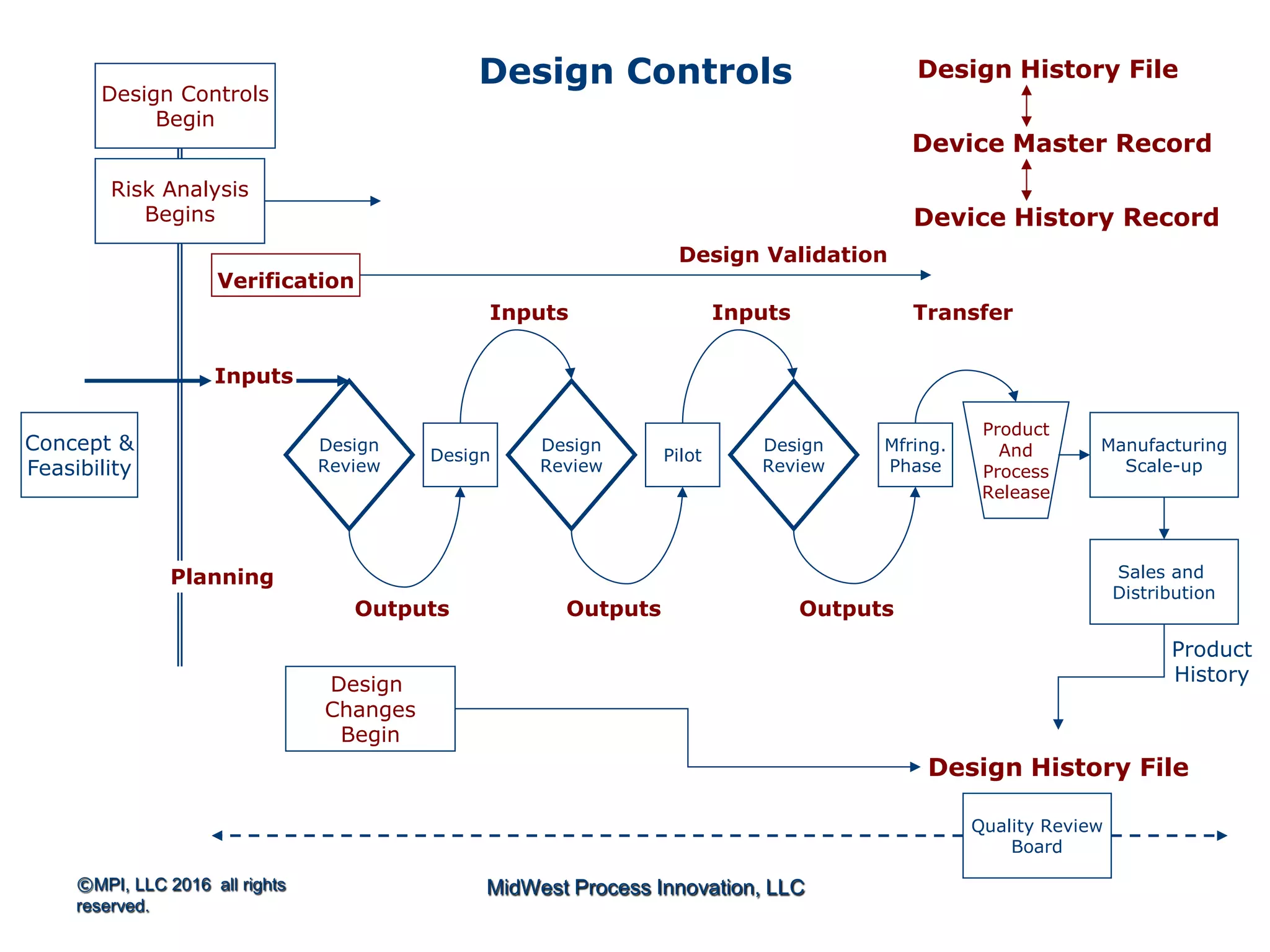
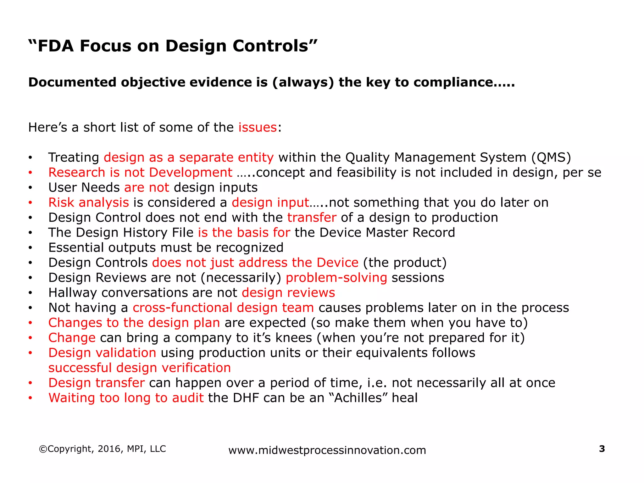
The document outlines FDA design control requirements under 21 CFR Part 820, emphasizing the importance of integrating design within the quality management system. It highlights critical issues like the necessity for comprehensive design inputs, the significance of documented objective evidence for compliance, and the necessity of cross-functional teams. Additionally, it addresses the relationship between design validation, risk analysis, and the creation of essential regulatory documentation like the Design History File (DHF) and Device Master Record (DMR).
Introduction to FDA regulations focusing on Design Controls for medical devices, emphasizing the importance of designing securely and efficiently.
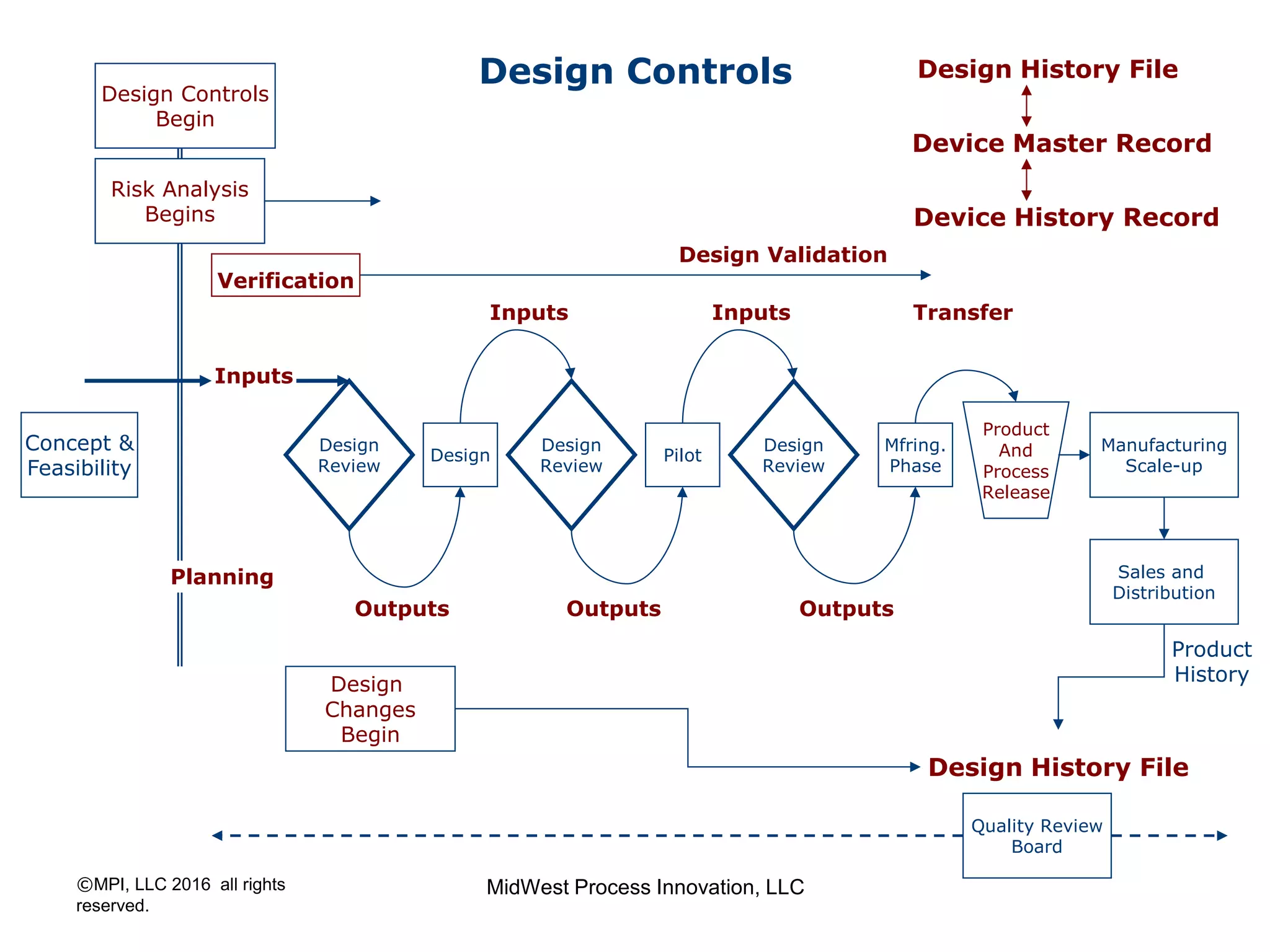
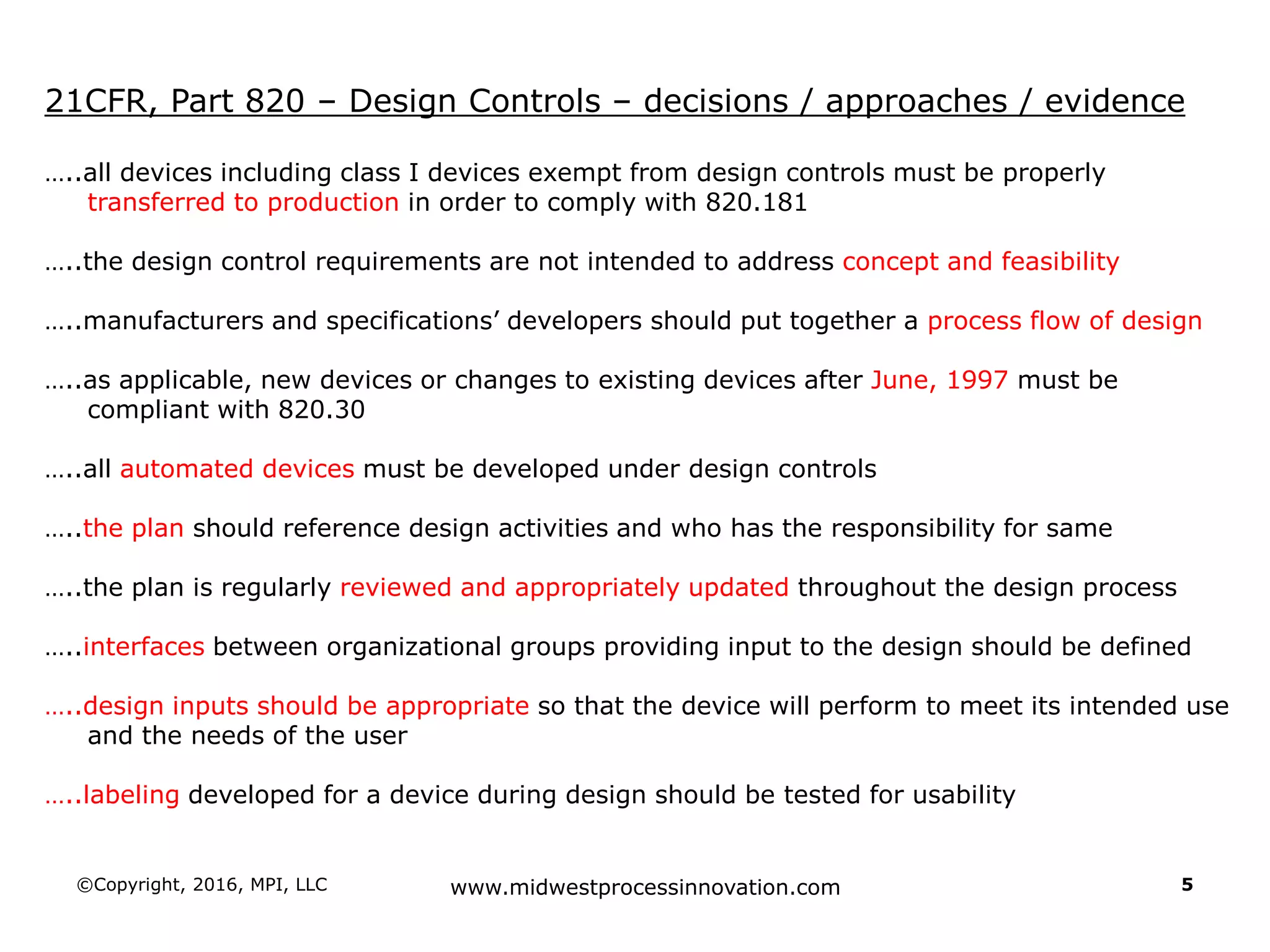
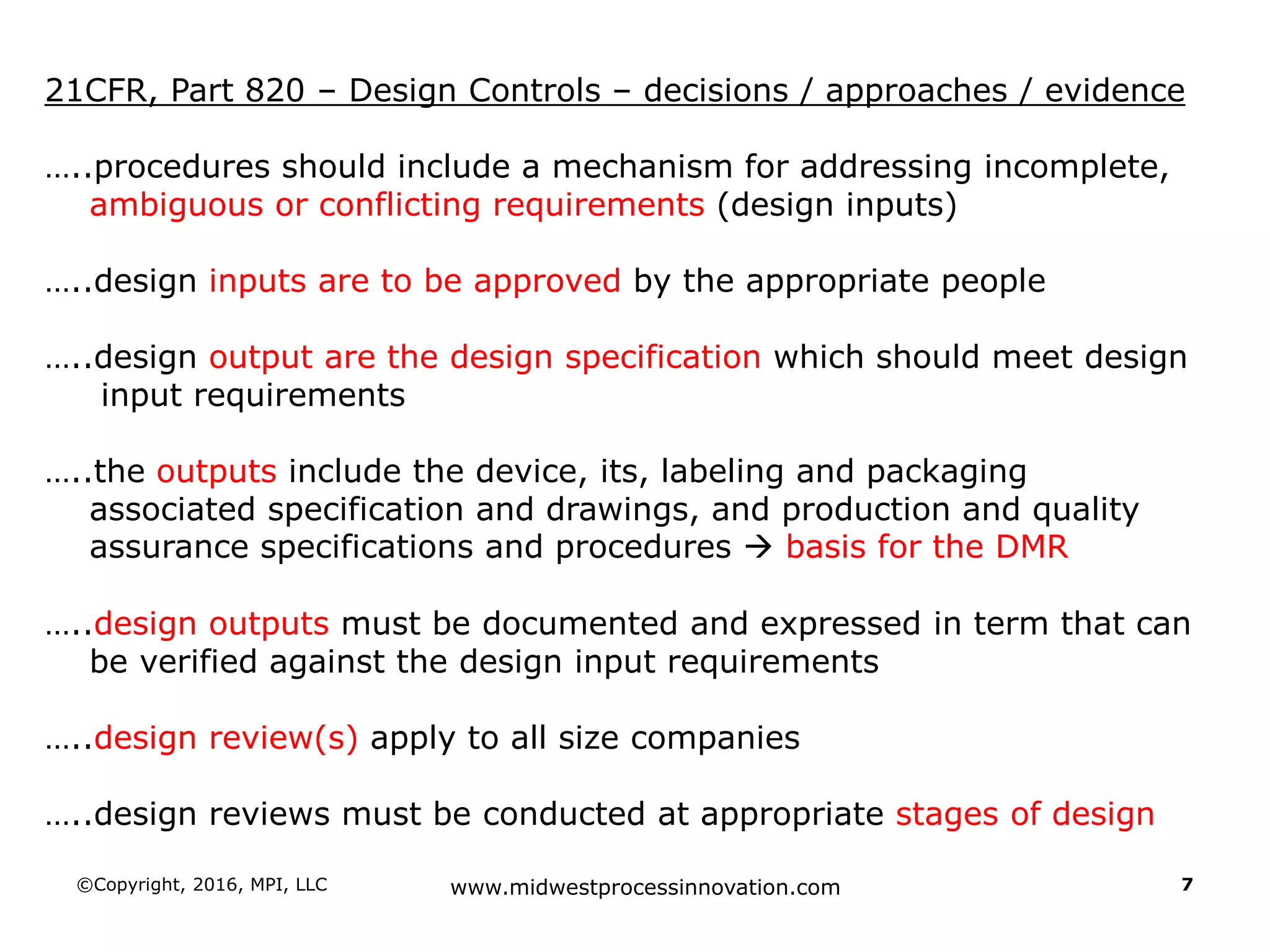
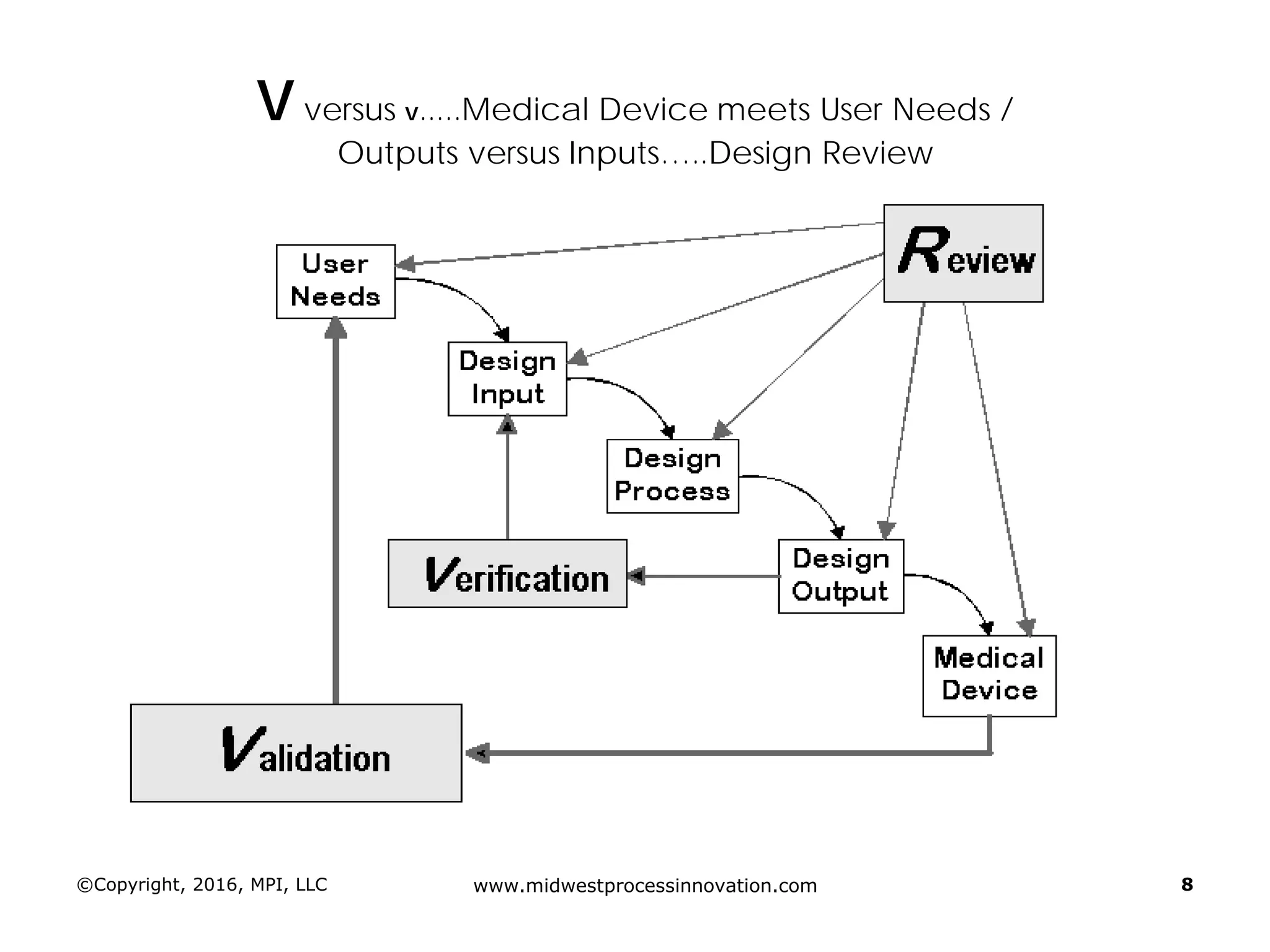
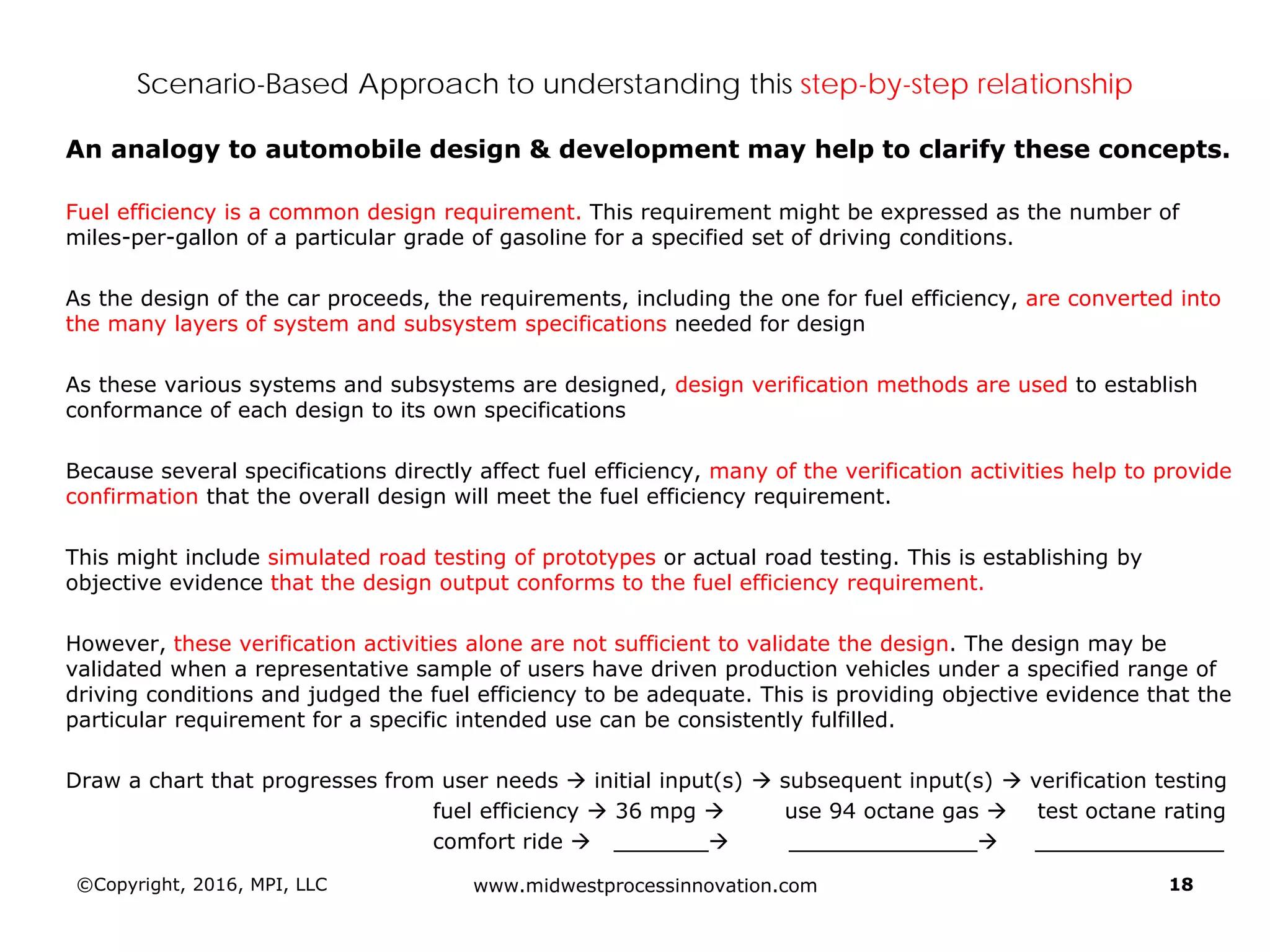
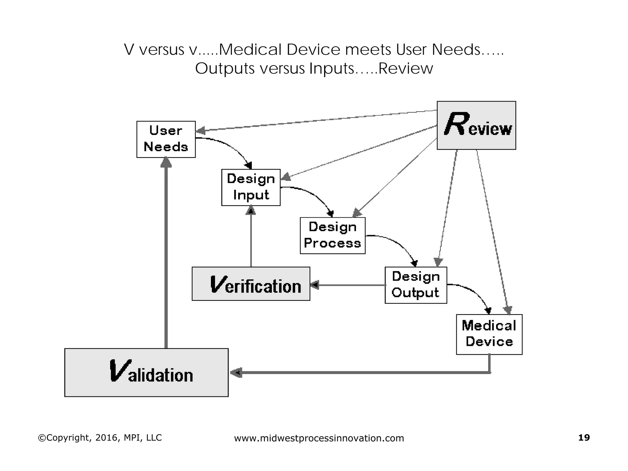
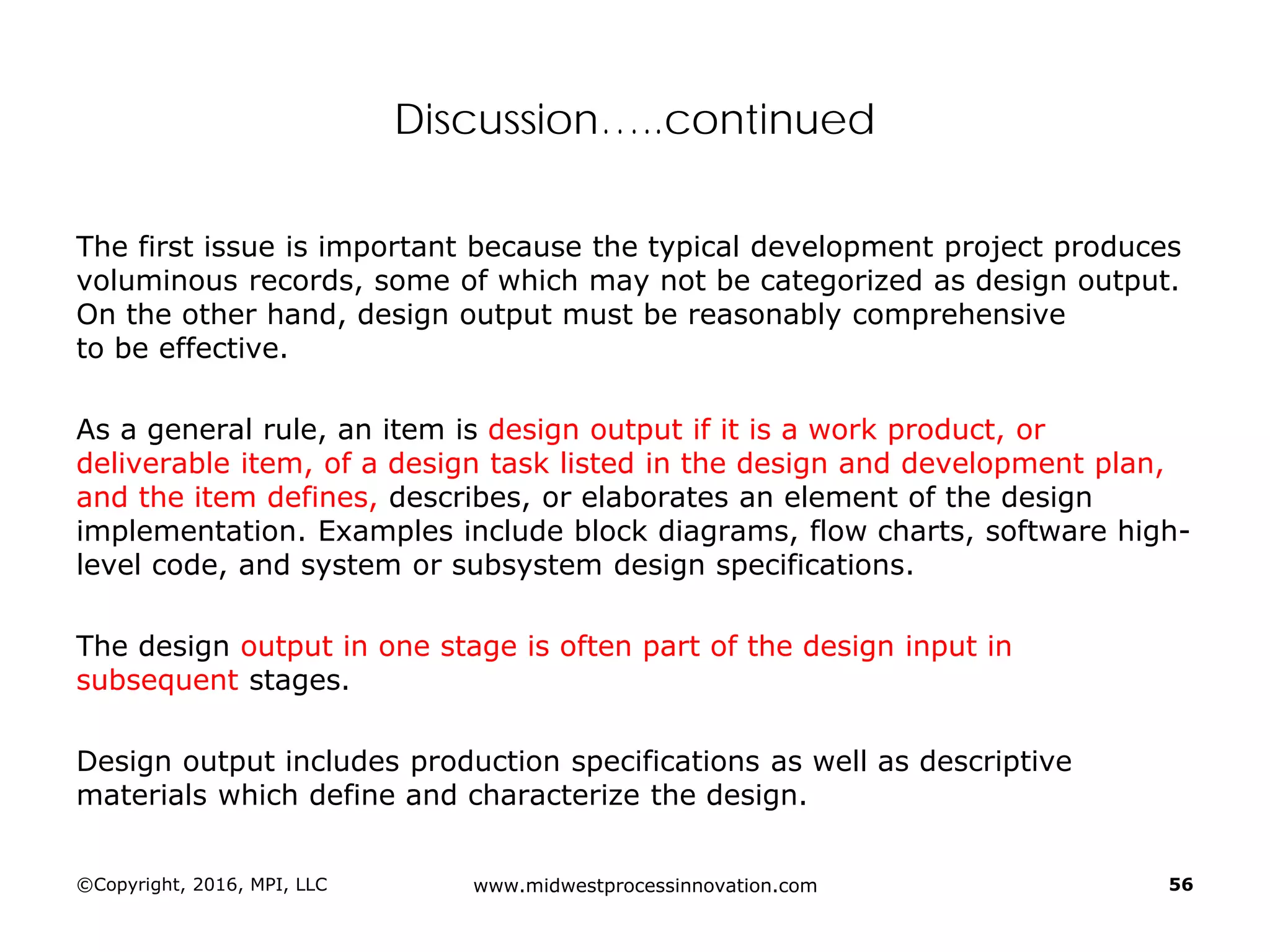
Establishing design inputs based on user needs and their approval process, ensuring that outputs meet these requirements.
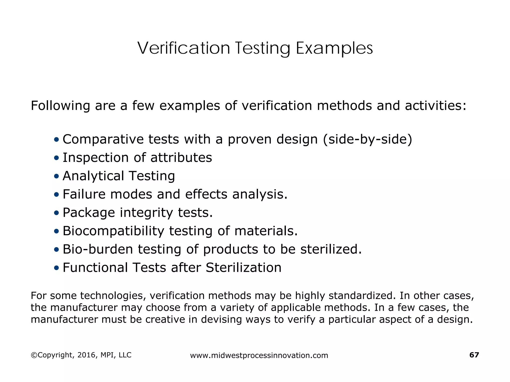
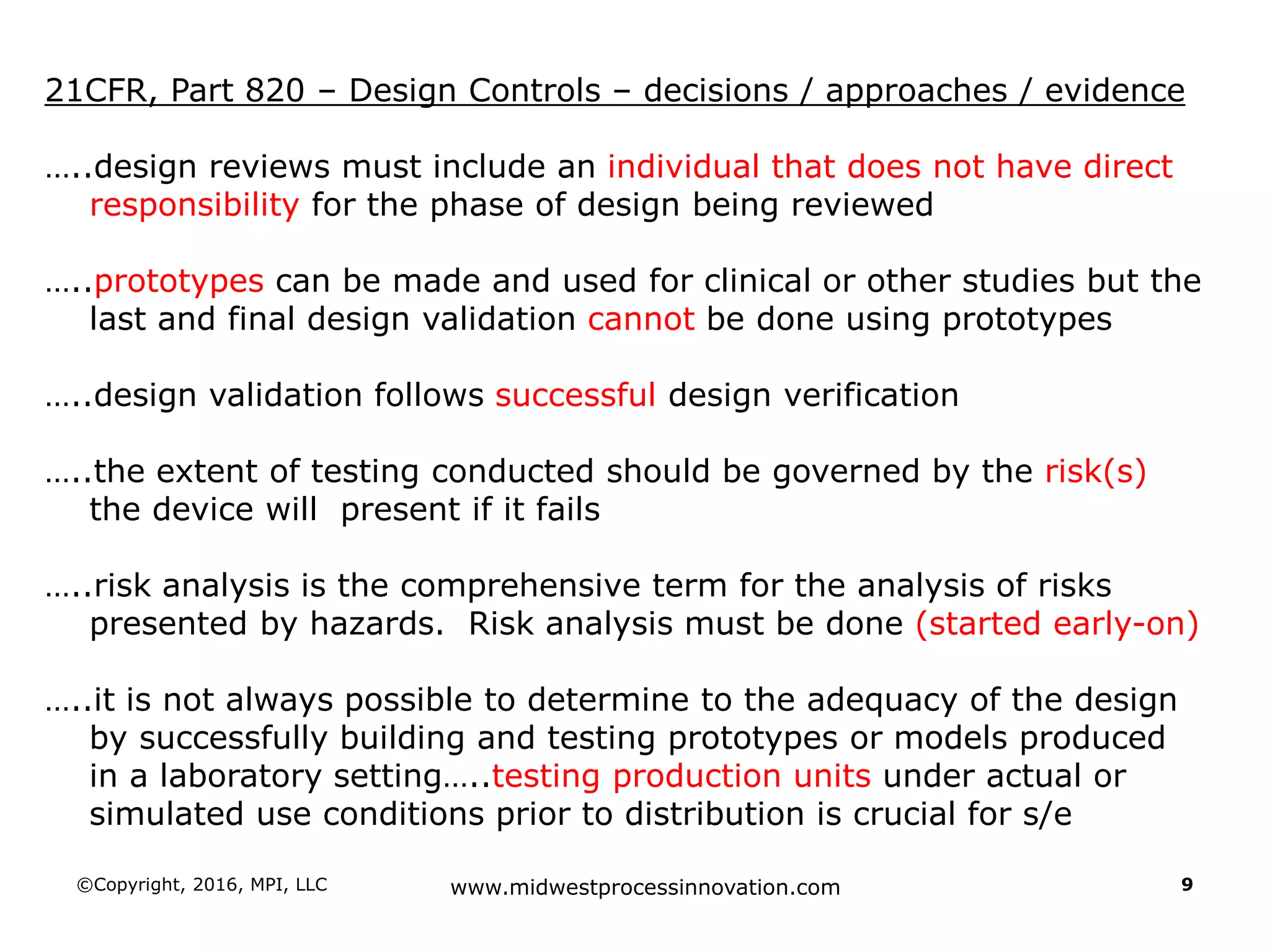
Emphasizes the importance of design validation after successful verification, and the role of risk analysis in testing.
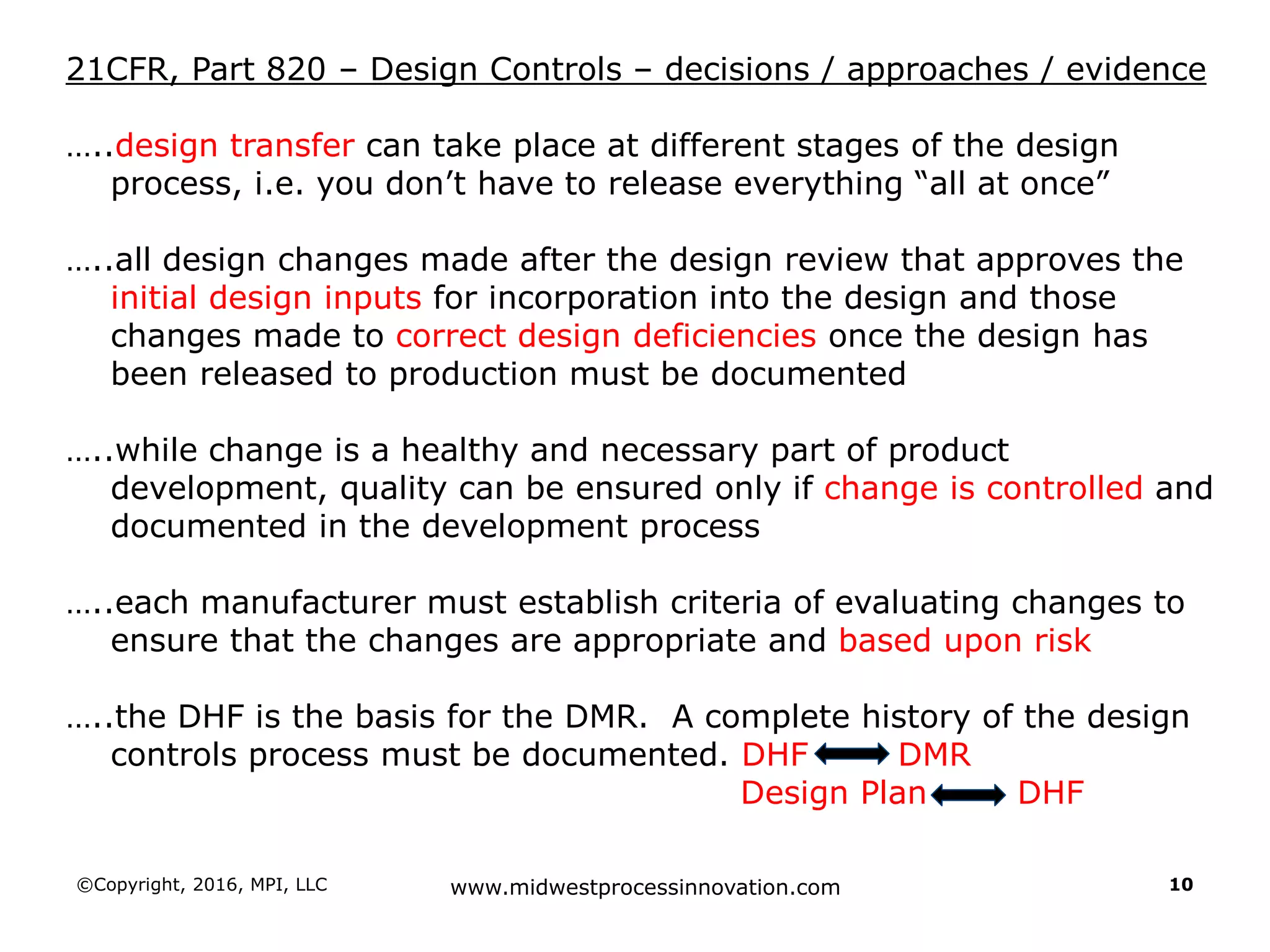
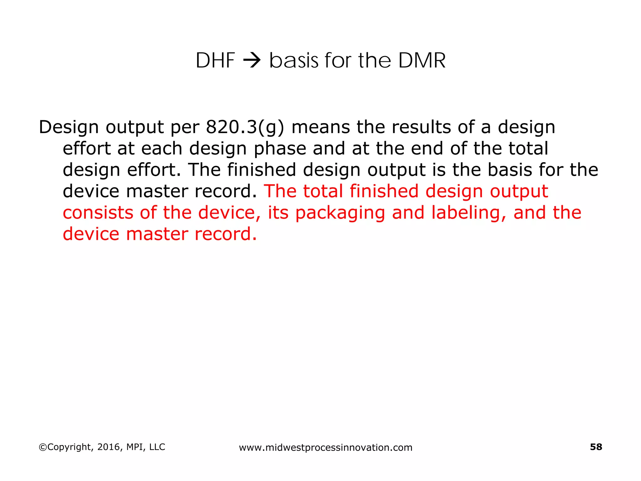
Describes processes for design changes, including importance of documentation and maintaining a Design History File (DHF).
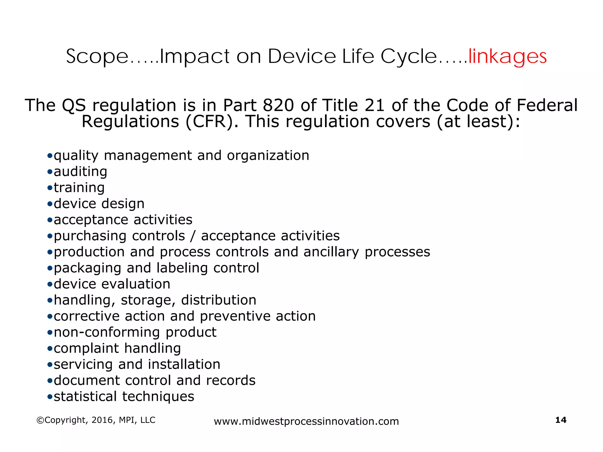
Introduction to 21 CFR Part 820 requirements covering quality management, design, and production processes for medical devices.
Clarifies differences between research and development, stressing the need for detailed specifications as inputs for design.
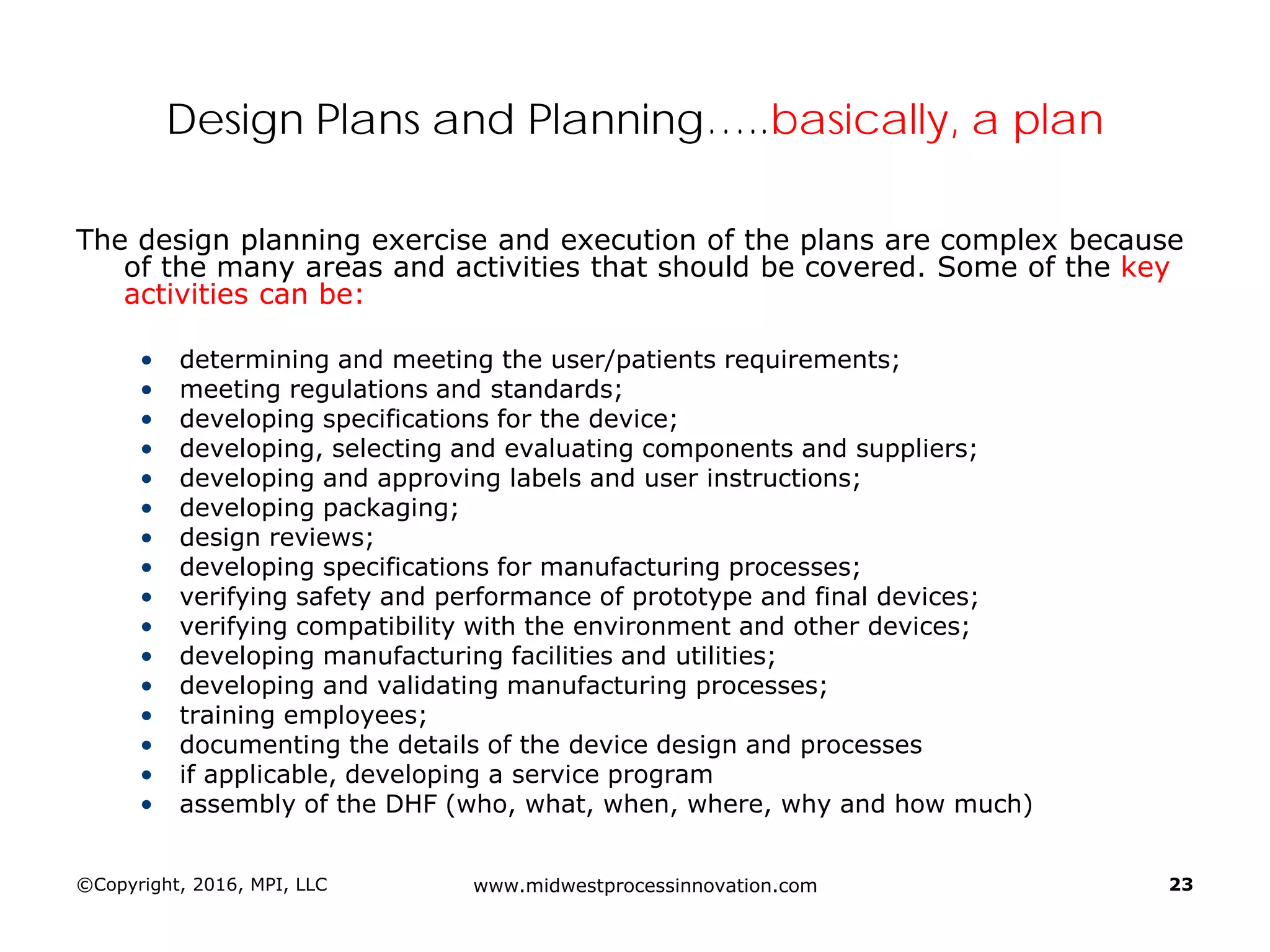
Discusses design planning stages and their impact on the device lifecycle, including necessary training and documentation.
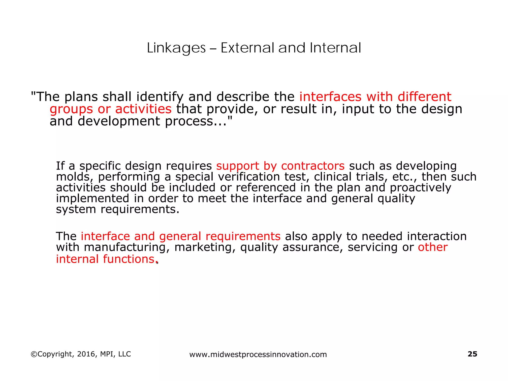
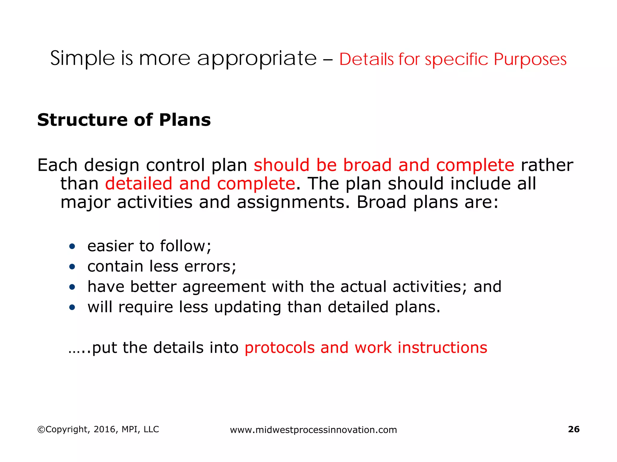
Structure for design control plans, identifying key activities and establishing proper interfaces throughout the design process.
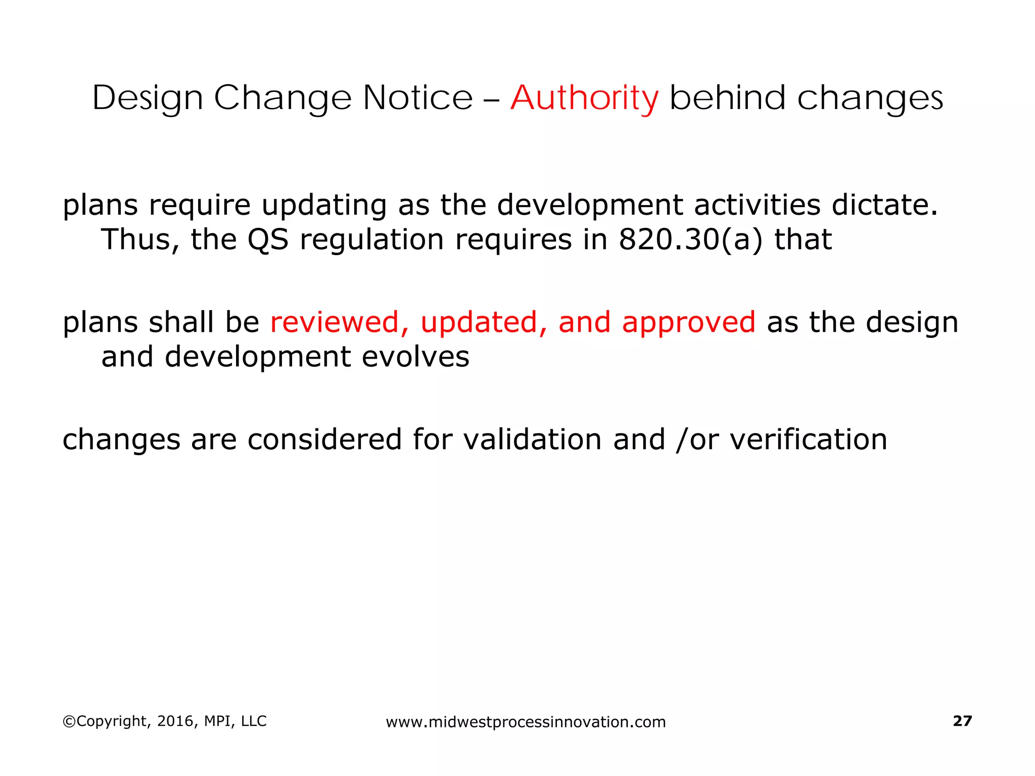
Requirements for establishing and maintaining design change controls, ensuring thorough documentation and verification.
Discussion of the design review process, its significance in evaluating design adequacy and ensuring comprehensive documentation.
Focuses on the requirements and processes for validation and verification documentation ensuring compliance and quality.
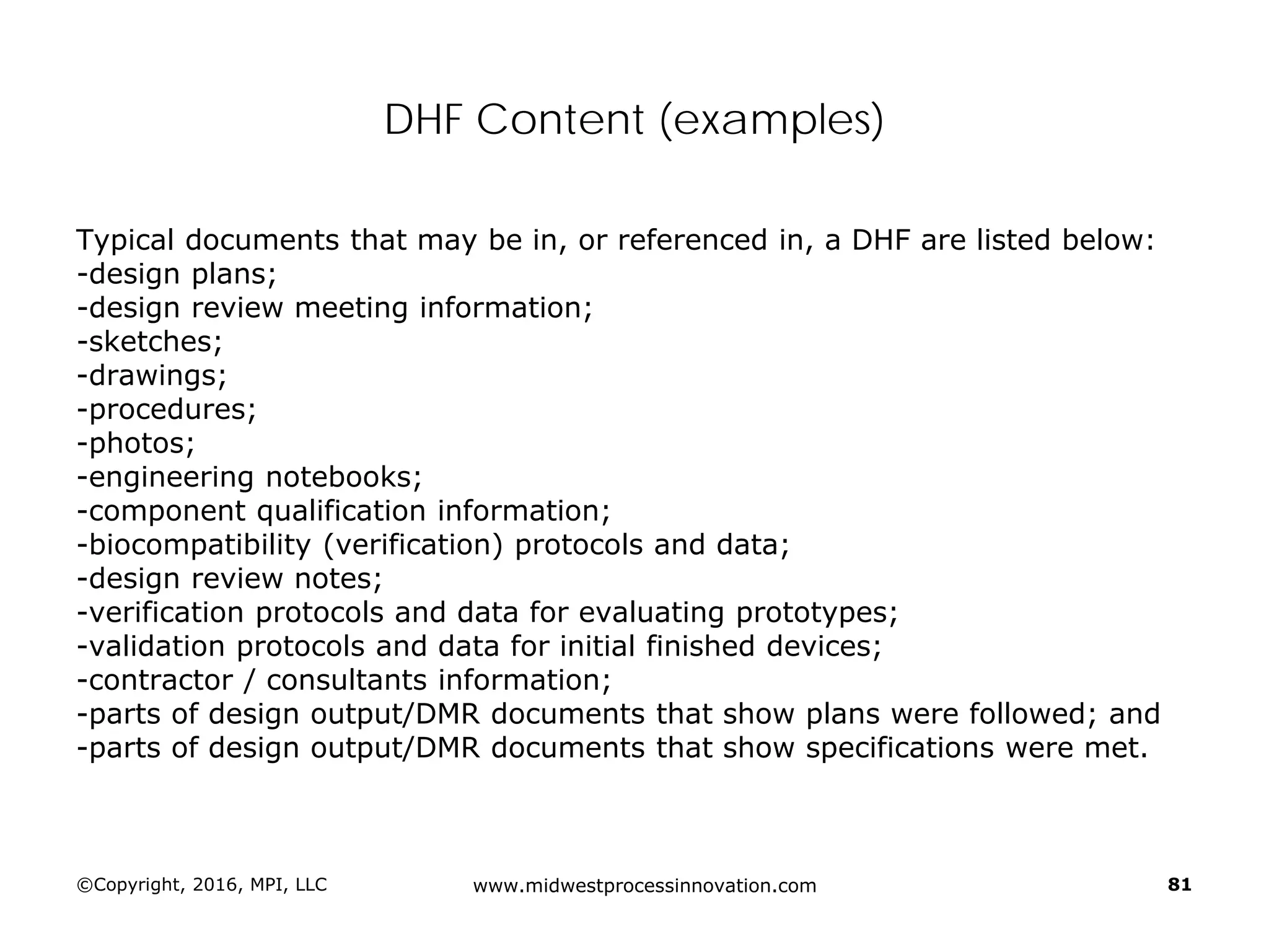
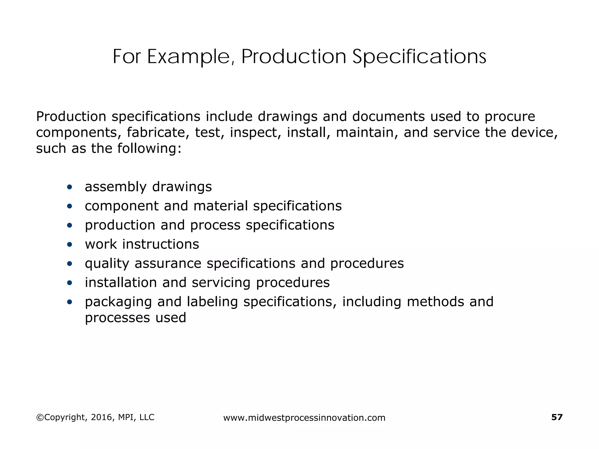
Explains design transfer requirements, emphasizing the importance of details in production specifications ensuring device quality. Details on what constitutes a DHF, including necessary documentation to support design quality and investigations.
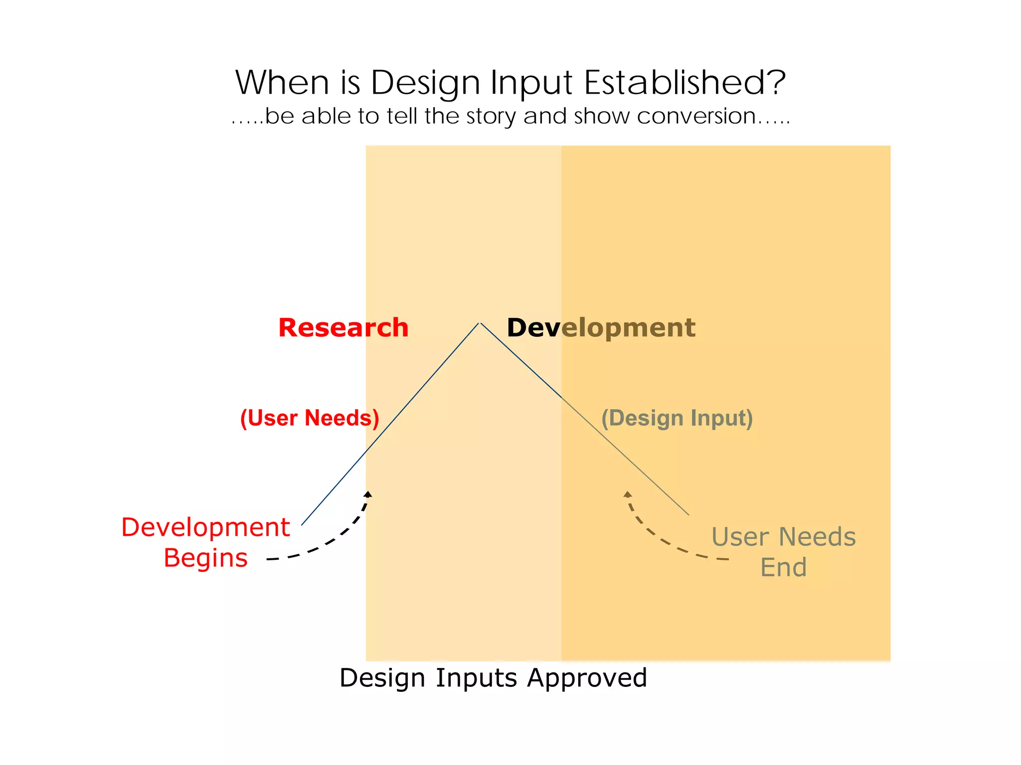
When is DesignInput Established?
…..be able to tell the story and show conversion…..
Design Inputs Approved
(User Needs) (Design Input)
Development
Begins
User Needs
End
Research Development
When is DesignInput Established?
…..be able to tell the story and show conversion…..
Design Inputs Approved
(User Needs) (Design Input)
Development
Begins
User Needs
End
Research Development


![©Copyright, 2016, MPI, LLC www.midwestprocessinnovation.com 24
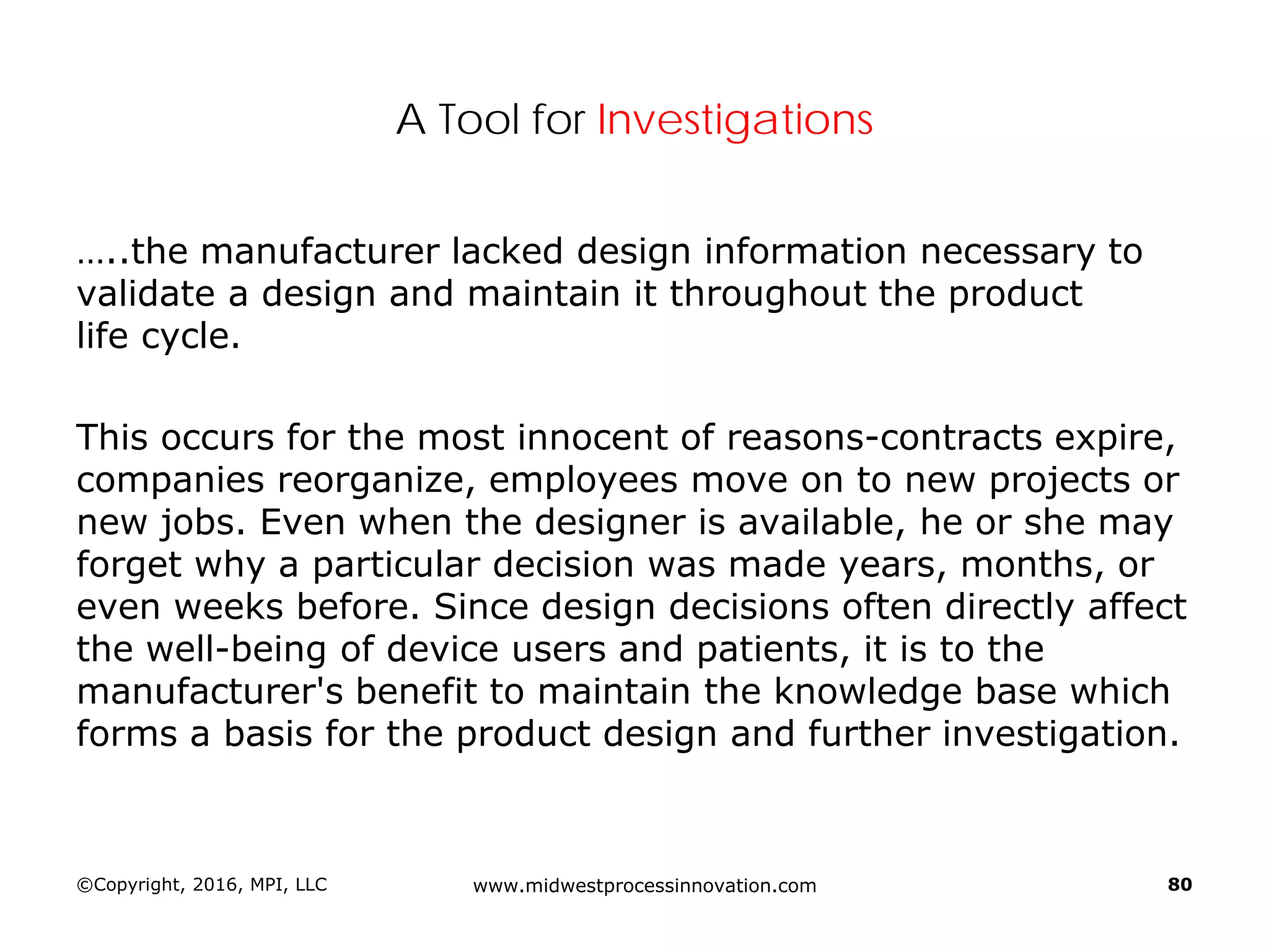
DHF at the Beginning…..References…..Outputs are the Basis for DMR
The design controls section of the quality system requires a
design history file (DHF) [820.30(j)] that contains or
references the records necessary to demonstrate that the
design was developed in accordance with the:
1. approved design plan, and
2. regulatory requirements
Start thinking in terms of essential outputs](https://image.slidesharecdn.com/omtec-2016gagliardidesign-controls-160620182518/75/FDA-Focus-on-Design-Controls-25-2048.jpg)


![©Copyright, 2016, MPI, LLC www.midwestprocessinnovation.com 47
Stage-gate…..Cross-functional thinking…..third party
Design review [820.30(e)] is one of the key design
control elements in a quality system. The
objectives of design review are stated in the
definition of design review in 820.3(h) as follows:
Design review means a documented,
comprehensive, systematic examination of
a design to evaluate the adequacy of the design
requirements, to evaluate the capability of the
design to meet these requirements, and to
identify problems.](https://image.slidesharecdn.com/omtec-2016gagliardidesign-controls-160620182518/75/FDA-Focus-on-Design-Controls-48-2048.jpg)
![©Copyright, 2016, MPI, LLC www.midwestprocessinnovation.com 50
Pre and Post Design Review(s)
Pre- and post-review meeting significant responsibilities and
assignments should be documented [820.30(b)]. These
assignments are not unusual -- they are simply ordinary work
required to develop a new product or modify an existing product.
The progress and/or results of such assignments would typically
be reported at the next review meeting.](https://image.slidesharecdn.com/omtec-2016gagliardidesign-controls-160620182518/75/FDA-Focus-on-Design-Controls-51-2048.jpg)


![©Copyright, 2016, MPI, LLC www.midwestprocessinnovation.com 62
SOP…..Output meets Input Requirements…..Objective
Evidence
DESIGN VERIFICATION
Each manufacturer shall establish and maintain procedures for
verifying the device design. Design verification [820.30(f)] shall
confirm that the design output meets the design input requirements.
The results of the design verification, including identification of the
design, method(s), the date, and the individual(s) performing the
verification, shall be documented in the DHF.
Verification means confirmation by examination and provision of
objective evidence that specified requirements have been fulfilled.](https://image.slidesharecdn.com/omtec-2016gagliardidesign-controls-160620182518/75/FDA-Focus-on-Design-Controls-63-2048.jpg)