Power Optimized Datapath Units of Hybrid Embedded Core Architecture Using Clock Gating Technique

Minimizing power consumption is a primary consideration in hardware design of portable devices where high performance and functionality is required with limited battery power. With the scaling of technology and the need for high performance and more functionality, power dissipation becomes a major bottleneck for microprocessor systems design. Clock power can be significant in high performance systems. Dynamic power can contribute up to 50% of the total power dissipation. The main goal of this work is to implement a prototype power optimized datapath unit and ALU of Hybrid Embedded Controller Architecture targeted on to the FPGA chip and analyze the power consumption of the datapath, ALU etc. Dynamic power management system which includes clock gating, qualified system latches are incorporated into this design. The whole design is captured using VHDL make use of Xilinx tool. This paper gives complete guidelines for authors submitting papers for the AIRCC Journals.

Recommended
Recommended
More Related Content
What's hot
What's hot (18)
Viewers also liked
Viewers also liked (19)
Similar to Power Optimized Datapath Units of Hybrid Embedded Core Architecture Using Clock Gating Technique
Similar to Power Optimized Datapath Units of Hybrid Embedded Core Architecture Using Clock Gating Technique (20)
Recently uploaded
Recently uploaded (20)
Power Optimized Datapath Units of Hybrid Embedded Core Architecture Using Clock Gating Technique
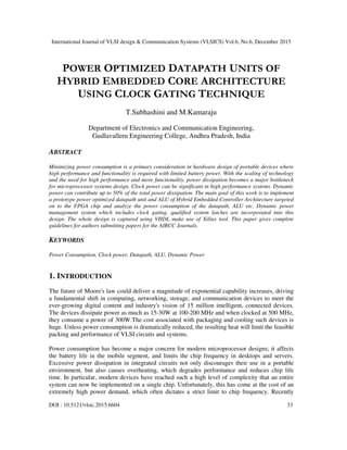
- 1. International Journal of VLSI design & Communication Systems (VLSICS) Vol.6, No.6, December 2015 DOI : 10.5121/vlsic.2015.6604 33 POWER OPTIMIZED DATAPATH UNITS OF HYBRID EMBEDDED CORE ARCHITECTURE USING CLOCK GATING TECHNIQUE T.Subhashini and M.Kamaraju Department of Electronics and Communication Engineering, Gudlavalleru Engineering College, Andhra Pradesh, India ABSTRACT Minimizing power consumption is a primary consideration in hardware design of portable devices where high performance and functionality is required with limited battery power. With the scaling of technology and the need for high performance and more functionality, power dissipation becomes a major bottleneck for microprocessor systems design. Clock power can be significant in high performance systems. Dynamic power can contribute up to 50% of the total power dissipation. The main goal of this work is to implement a prototype power optimized datapath unit and ALU of Hybrid Embedded Controller Architecture targeted on to the FPGA chip and analyze the power consumption of the datapath, ALU etc. Dynamic power management system which includes clock gating, qualified system latches are incorporated into this design. The whole design is captured using VHDL make use of Xilinx tool. This paper gives complete guidelines for authors submitting papers for the AIRCC Journals. KEYWORDS Power Consumption, Clock power, Datapath, ALU, Dynamic Power 1. INTRODUCTION The future of Moore's law could deliver a magnitude of exponential capability increases, driving a fundamental shift in computing, networking, storage, and communication devices to meet the ever-growing digital content and industry's vision of 15 million intelligent, connected devices. The devices dissipate power as much as 15-30W at 100-200 MHz and when clocked at 500 MHz, they consume a power of 300W.The cost associated with packaging and cooling such devices is huge. Unless power consumption is dramatically reduced, the resulting heat will limit the feasible packing and performance of VLSI circuits and systems. Power consumption has become a major concern for modern microprocessor designs; it affects the battery life in the mobile segment, and limits the chip frequency in desktops and servers. Excessive power dissipation in integrated circuits not only discourages their use in a portable environment, but also causes overheating, which degrades performance and reduces chip life time. In particular, modern devices have reached such a high level of complexity that an entire system can now be implemented on a single chip. Unfortunately, this has come at the cost of an extremely high power demand, which often dictates a strict limit to chip frequency. Recently
- 2. International Journal of VLSI design & Communication Systems (VLSICS) Vol.6, No.6, December 2015 34 growing demand for low-power portable devices and computing systems has created a need to limit the power consumption in many chip designs. Today, a large fraction of the overall power dissipation on a chip is due to clocks and datapath. Power consumption is one of the important factors in the design of integrated circuits especially in CPU designs. Power consumption is proportional to the square of supply voltage, which means that reducing a processor’s supply voltage can result in dramatic savings in power, but it will cause a reduction in performance, then the system clock must typically be reduced to ensure correct operation. Therefore any voltage reduction must be balanced against any performance drop. To maintain the same throughput, extra hardware can be added. 1.1 Clock Signal Power optimization strategies are based on the principle that complex digital circuits contain units that do not perform useful computation at every clock cycle. Hence, it is possible to reduce power dissipation by blocking logic switching activity that appears irrelevant during a particular clock cycle. The most important factor contributing to the power consumption is the switching activity. Once the technology and supply voltage have been set, major energy savings come from the careful minimization of switching activity. While some switching activity is functional, i.e. it is required to propagate and manipulate information; there is a substantial amount of unnecessary activity in almost all digital circuits. Unnecessary switching activity arises from spurious transitions due to unequal propagation delays and transitions occurring within units that are not participating in a computation. One way to avoid these activities is by dynamically turning off the clock to unused logic or peripherals. Clock gating is one of the techniques of dynamic power management to reduce the dynamic power consumption. Naturally in a processing unit clock runs continuously to all the blocks though there is no necessity of clock to all the blocks at the same time. By running the clock to the blocks where clock is unnecessary, clock power is wasted. To reduce the wastage of clock power, a gating circuit is implemented to stop the clock where clock is not used by the blocks. This is the main principle of the clock gating circuit. 1.2 Latches Clock transition is a major role of a processor power, because the clock is connected to all the circuit blocks of the processor, and switches every cycle. However, all the circuit blocks are not required all the time. The individual circuit/block usage varies within and across applications. In this technique, the clock is ANDed with a gate control signal, clock gating necessarily disables the clock to a circuit wherever the circuit is not used. In this way power dissipation is avoided due to unnecessary charging and discharging of the unused circuits. There are two types of clock gating circuits built with AND gate with active high and active low clock gating signal. The functionality of the clock gating circuit shown in Figure 1 depends on the active low clock gating signal. If this signal is active low, then the clock is allowed otherwise the clock is stopped in such a way as to reduce the unnecessary activity by means of reducing power dissipation. These techniques can be applied to the latches.
- 3. International Journal of VLSI design & Communication Systems (VLSICS) Vol.6, No.6, December 2015 35 Fig: 1 Schematic of Conventional latch (CL) Fig: 2 Schematic of gated latch (GL) By the clock gating technique, conventional or non-gated clock circuit as shown in figure 1 can be converted into a gated latch shown in figure 2 Clock pulses are not applied to the latch when the value of the clock gating signal is equal to ‘0’ thus saving the power dissipated in the latch and some parts of clock lines. When the clock switches every cycle, cumulative capacitance of the latch charges and discharges every cycle and consumes significant amount of power. Even if the inputs do not change from one clock to the next, the latch still consumes clock power. 2. POWER OPTIMIZED DATAPATH AND CONTROL UNITS Block diagram of power optimized data path and control unit is shown in figure 3, which consists of clock selection logic circuit, clock gating circuit, control unit and datapath. The decoded instruction is applied as input to the clock selection logic circuit and the control unit simultaneously. The clock selection logic circuit generates clock enable signals to particular modules based on the clock selection logic. The clock gating circuit then generates clock input signals to the modules specified by the clock selection logic circuit. At the same time, the control unit generates control and timing signals to particular modules to perform the desired operation based on the decoded instruction input. In this way unnecessary modules are turned off and only required modules turned on, thereby reducing the dynamic power consumption. Clock distribution without clock gating technique: figure 4 shows clock distribution to the datapath unit without clock gating technique. Data path unit consists of ALU, register file, RAM and immediate register, in which clock is given to all the modules. Clock power is consumed by all the units. But at any time only one unit is required to perform operation and hence this unit only needs clock signal. For the remaining units, there is no need of clock signal; clock should be idle. Fig: 3 Block Diagram of Processor’s Datapath and control unit employing clock gating technique.
- 4. International Journal of VLSI design & Communication Systems (VLSICS) Vol.6, No.6, December 2015 36 Fig: 4 Clock distribution without clock gating technique In this case whether clock is required or not, clock is derived to all the units, there by consuming more power. For example addition of two numbers enables the clock for registers and ALU block particularly adder/subtractor block. The remaining blocks are not participating in the addition process. In this way unnecessary power is consumed by the datapath unit. This problem can be reduced by employing clock gating technique, which allows the clocks to the desired units. Fig: 5 Clock distribution with clock gating Clock gating circuit generates gated clock signals based on the clock gating signals/enable signals to the various units of datapath unit which only requires the clock; for remaining units clock is not fed. These clock enable signals are generated by clock selection logic circuit, which works on the type of instruction to be executed. Based on the decoded instruction input, unnecessary modules are turned ‘OFF’, and only required modules turned ‘ON’, thereby reducing power consumption. In unnecessary modules, the charging and discharging of the capacitance Cg will not occur thus reducing the capacitance effect of all unnecessary modules. In this way dynamic power consumption is reduced. The flow chart for clock gating circuit is shown in figure 6. Only when the clock event and clock enable signal occurs, it allows clock signal to the required module.
- 5. International Journal of VLSI design & Communication Systems (VLSICS) Vol.6, No.6, December 2015 37 Fig: 6 Flow chart of Clock Gating Circuit 2.1. Clock Selection and Control Unit Clock selection logic circuit consists of combinational elements, and determines whether a clock pulse should be applied to the functional units or not. If the output of the clock selection logic is equal to zero, a clock pulse is not propagated to the clock inputs of the units, for example: Registers, functional units etc. This unit generates clock enable signals based on the decoded instruction input signal. Control unit generates control signals like read and write as well as select/enable signals to the datapath unit. The decoded instruction signals are the inputs for the control unit. This unit selects/enables the various units of datapath. Then the datapath unit performs operations based on the control signals. Figure 7 shows connections/signals between control unit and datapath unit. Control unit generates various control signals to control the datapath unit. The following signals are generated by the control unit by taking decoded instruction input, sel_alu, sel_log, sel_ar, sel_sh, sel_mul, we, weram, eimm. In which sel_alu signals selects the various blocks of ALU unit, sel_log signals selects the logical operations, sel_ar signals selects the arithmetic operations like addition, subtraction etc, sel_sh selects shifting operations, sel_mul to select the multiplication operation, we signal enables the register bank, weram enables the RAM, eimm enables the immediate register. Fig: 7 Signals between control unit and datapath unit
- 6. International Journal of VLSI design & Communication Systems (VLSICS) Vol.6, No.6, December 2015 38 Fig: 8 New ALU module ALU takes 16-bit operands as inputs, process the operand data and gives 16-bit output data. ARTH_1 block performs addition, subtraction, increment, and decrement operations, ARTH_2 block performs multiplication, addition with 1, register A contents to be cleared, and A register contents set to all ones operations. Logical_1 block performs NOT/compliment, AND, OR, EXOR logical operations and LOGICAL_2 block the shift, rotate operations either to left or right. Figure 9 shows clock distribution in new ALU in which clock signals are not directly connected to the functional units (FUs) of ALU section. Instead, clock signals are gated with coded signals and are fed to the desired functional units. For example, while ARTH_1 is performing operations, remaining functional blocks ARTH_2, LOGICAL_1 and LOGICAL_2 are not performing any operations, such that, clock signal is delivered only to ARTH_1 functional unit. Fig: 9 Clock distributions in new ALU To implement clock gating circuit, an algorithm is implemented, in which the clock signal is allowed to the required module only, when the clock event and clock enable signal occurs.
- 7. International Journal of VLSI design & Communication Systems (VLSICS) Vol.6, No.6, December 2015 39 3. RESULTS The whole design is captured in HDL and simulated, synthesized using Xilinx tool. The dynamic power was measured using Xpower power analysis tool and the design was successfully tested with and without clock gating technique. Gated latch for different input and clock enable conditions are verified by simulating the latch. From the simulation results it is understood that the clock is allowed to the latch only when the input data is to be latched. When clock gating signal (en) is ‘1’, clock is enabled and if the signal is ‘0’, clock is disabled. Thus there is a control on the clock by the clock gating signal. Figure 10 shows the RTL schematic of simple/conventional latch without clock gating technique and figure 11 that of the gated latch (conventional latch with clock gating). Fig: 10 RTL schematic of conventional latch without clock gating Fig: 11 RTL schematic of gated latch (conventional latch with clock gating) Figure 12 shows the power analysis of conventional latch (CL) and gated latch (GL). The result shows that dynamic power consumption of GL is less as compared to that of CL. The disadvantage of GL is that there is no data circulation.
- 8. International Journal of VLSI design & Communication Systems (VLSICS) Vol.6, No.6, December 2015 40 Fig: 12 Power consumption of CL and GL 3.1 Datapath and Control Unit The various blocks of Low power datapath and control unit viz. clock gating circuit, ALU, shifting unit, RAM, register bank, control unit and clock selection logic circuits are simulated for their functional verification and RTL schematics are obtained. The simulation of various blocks are done by applying different input conditions, the outputs are observed and found that units are functioning properly. Top level module RTL viewer is shown in figure 13. The decoded instruction is applied as input to the selection logic circuit. Based on the selection logic, clock enable signals are generated and are applied to the required modules through clock gating circuit. At the same time control unit generates control signals to these modules based on decoded instruction input to perform the required operations. Fig: 13 RTL schematic of top level module of data path and control unit The Power dissipation when clock is applied directly to all the modules is found to be 18.43mW irrespective of the instruction executed. Comparison of the power dissipation for 8 different instructions without and with clock gating is shown in figure 14. In all the cases the power
- 9. International Journal of VLSI design & Communication Systems (VLSICS) Vol.6, No.6, December 2015 41 consumption with clock gating is found to be less as compared to that without clock gating. A maximum power saving of 15.63% is achieved for the decoded instruction of 000. Power consumed by the top level module is found to be 18.43mW without clock gating and only 15.55mW after clock gating technique is employed, thus achieving a power saving of 15.63%. Fig: 14 Power consumption of data path and control unit without and with clock gating The functional verification of the circuit is done by simulation of different blocks of datapath and control units of processor. This unit can be used in the design of microprocessor architecture and low power applications. Power can be reduced further by applying the clock gating technique at a higher level of granularity. 3.2 Power Optimized ALU A 16-bit ALU is implemented which performs eight arithmetic and eight logical operations selected by a 4-bit code. The RTL viewer of ALU is shown in figure 15. From this figure, it can be observed that the clock gating circuit controls the clock for different sections of ALU. Fig: 15 RTL schematic of new ALU
- 10. International Journal of VLSI design & Communication Systems (VLSICS) Vol.6, No.6, December 2015 42 The power consumption of new ALU at different frequencies new ALU shown in figure 16. New ALU is tested for different frequencies at supply voltages of 1.2v and 1.4v. The results show that on average the power consumption of the new ALU is 19.8mW. It is less as compared to the ALU operated at 2.4v (figure 7.20). Fig: 16 Power consumption of new ALU at different frequencies The characteristics of new ALU are taking less time to perform ALU operation and simulation time also less, consuming less power after clock gating technique is employed, less number of gates used in this design, less delay. It is suitable for PEC core design and it can be used in any low power applications where integer ALU is required. 4. CONCLUSIONS The average power consumption of datapath and control unit is 17.75mW, operating frequency is 1664.032MHz and its simulation time is 8.18 µs. A maximum power saving of about 15.63% is achieved with clock gating over that when no clock gating is employed. After applying the clock gating technique applied to the sub modules of new ALU, power saving on average of 4.75mW in terms of percentage power saving will be 23.98%. The average power consumption of new ALU is 19.8mW. Significant power saving achieved through applying clock gating technique to datapath unit and ALU. REFERENCES [1] Aaron.P.H., “Automatic Synthesis of Clock Gating Logic with Controlled Netlist Perturbation,” Proc. of 45th ACM/IEEE Design Automation conf. 2008 (DAC 2008), 2008, pp. 654 – 657. [2] Agarwal.N and Dimopoulos.N, “High Level Fixed Point VLSI Design with Automated Clock Gating,” Proc. of IEEE Pacific Rim Conf. on Communications, Computers and Signal processing (PACRIM'07) IEEE, 2007, pp. 359 – 362. [3] Ahmad Zmily and Christos Kozyrakis, “A Low Power Front-End for Embedded Processors Using a Block-Aware Instruction Set,” Proc. of the Automation Science & Engineering (CASE 07), 2007, pp. 267-276.
- 11. International Journal of VLSI design & Communication Systems (VLSICS) Vol.6, No.6, December 2015 43 [4] Ajun.K, Nikhil.J, and Sunil.P.K., “A Novel Clock Distribution and Dynamic De-skewing Methodology,” Proc. IEEE/ACM of Int’l conf. on computer aided design (ICCAD2004), 2004, pp. 626-631. [5] AnanthaChandrakasan and Robert Broderson,” LOW POWER CMOS DESIGN”, IEEE press,2000,pp 233-238. [6] Arindam.M and MalgorzataMarek-Sadowska, “Clock and Power Gating with Timing Closure,” Proc. of IEEE Design and Test of Computers IEEE, 2003, pp. 32-39. [7] Babighian.P, Benin.L and Macii.E. , “A scalable algorithm for RTL insertion of gated clocks based on ODCs computation,” IEEE Trans. on Computer-Aided Design of Integrated Circuits and Systems, Vol.24, No.1, 2005, pp. 29-42. [8] Barry Fagin and Cyril Renard, “Field Programmable Gate Arrays and Floating Point Arithmetic,” IEEE Trans. on Very Large Scale Integration (VLSI) Systems, Vol. 2, No. 3, 1994, pp. 365-367. [9] Benin.L, and Micheli.G.D, “Automatic Synthesis of Low-Power Gated Clock Finite State Machines,” IEEE Transactions on Computer -Aided Design of Integrated Circuits and Systems, Vol. 15, N0. 6, 1996, pp. 630-643. [10] Bill Moyer, “Low Power Design for Embedded Processor”, Proc. of IEEE, Vol.89, No.11, 2001, pp.1576-1586. [11] Castro.J, Parra.P, and Acosta.A.J., “Optimization of Clock-gating Structures for Low-leakage High- performance Applications,” Proc. of 2010 IEEE Int’l Symp. on Circuits and Systems (ISCAS), 2010, pp. 3220 – 3223. AUTHORS Mrs.T.Subhashini : She got B.Tech in ECE from ANU, Guntur during 2005, M.Tech in Digital Electronics & Comm. Systems from JNTUK, Kakinada during 2011. Having Experience of 5 years in the field of teaching experience of 5 years in the area of ECE. Published 13 research papers at various international journals, international conferences and national conferences. The areas of interest are Low poer VLSI Design, Designing Digital Systems. She is a Associate member of Institution of Engineers. Presently she is working as Assistant Professor in the department of Electronics and Communication Engineering, Gudlavalleru Engineering College, Gudlavalleru . Dr.Maddu.Kamaraju : He got B.E in ECE from during 1993, M.E in Electronic Instrumentation from Andhra University, Visakhapatnam during 2001, Ph.D in Electronics and Communication Engineering with a specialization of Low Power VLSI Design by JNTUH,Hyderabad June 2012. Having Experience of 22 years in the field of teaching and research experience of 5 years in the area of VLSI design. Published 71 research papers at various international journals, international conferences and national conferences. Editorial board member of International journal of VLSI Design and Communication Systems (IJVLSICS) and Reviewer for number of International Journals. Designated reviewer for various IEEE international conferences organized outside of INDIA. He is a Fellow member of IETE and IE and member of IEEE.He elected as Chairman of Institution of Engineers, Vijayawada Centre for the years 2014-2016. Presently he is working as Professor & Head in the department of Electronics and Communication Engineering, Gudlavalleru Engineering College, Gudlavalleru .