SlideShare a Scribd company logo
1 of 30
Download to read offline
Ver 11.1 1
Mobile Adhoc Networks (MANETs)
Contents
1 Introduction..........................................................................................................................3
2 Simulation GUI......................................................................................................................3
2.1 Fast Configuration .....................................................................................................................4
2.2 Create Scenario..........................................................................................................................7
2.2.1 Single MANET ...........................................................................................................7
2.2.2 Multiple MANETs......................................................................................................8
2.2.3 Bridge Node..............................................................................................................9
2.3 Set Node, Link and Application Properties..............................................................................10
2.4 Enable Packet Trace, Event Trace & Plots (Optional)..............................................................12
2.5 Run Simulation.........................................................................................................................12
3 Model Features...................................................................................................................13
3.1 Adhoc On Demand Vector Routing .........................................................................................13
3.2 Link Layer Acks and Network Layer Acks in DSR......................................................................13
3.2.1 Using Link-Layer Acknowledgements.....................................................................13
3.2.2 Using Network-Layer Acknowledgements .............................................................14
3.3 Mobility models in Netsim.......................................................................................................15
3.3.1 Random Walk Mobility Model................................................................................15
3.3.2 Random Waypoint Mobility Model........................................................................15
3.3.3 Group Mobility Model............................................................................................16
3.3.4 File Based Mobility Model......................................................................................16
3.4 Visualizing node movement in NetSim animator....................................................................18
4 Featured Examples..............................................................................................................19
4.1 AODV Routing..........................................................................................................................19
4.2 ZRP-IARP ..................................................................................................................................21
4.3 ZRP-IERP...................................................................................................................................25
4.4 MANET-OLSR ...........................................................................................................................26
5 Reference Documents .........................................................................................................30
Ver 11.1 2
6 Latest FAQs.........................................................................................................................30
Ver 11.1 3
1 Introduction
NetSim MANET supports the following protocols
 Layer 3
o Dynamic Source Routing (DSR)
o Adhoc On demand Vector Routing (AODV)
o Optimized Link state Routing (OLSR)
o Zone Routing Protocol (ZRP)
 MAC / PHY
o 802.11 a, b, g, n, ac and e
NetSim MANETs component can be interfaced with
 Component 6 (IOT) module to run 802.15.4 in MAC/PHY
 Component 9 (VANETs) module to run IEEE 1609 WAVE in MAC/PHY
 Military Radio Add on to run TDMA/DTDMA in MAC/PHY
2 Simulation GUI
In the Main menu select New SimulationMobile Adhoc networks Single MANET/
Multiple MANETs
Ver 11.1 4
2.1 Fast Configuration
Ver 11.1 5
Fast Config window allows users to define device placement statergies and conveniently
model large network scenarios especially in network such as MANET, WSN and IoT. The
parameters associated with the Fast Config Window is explained below:
Grid length: It is the area of simulation environment. Users can change the length of the grid
in the range of 50-1000000m
Side length: It specifies the area in the grid environment withing which the devices will be
placed. User can change the side length of the grid in the range of 50 - 1000000m.Side length
should be multiple of 50. Side length should always be set to a value greater than or equal to
the Grid length.
Device Placement:
Automatic Placement:
1. Uniform Placement: Devices will be placed uniformly with equal gap between the devices
in area as specified in side length. This requires users to specify the number of devices as
square number. For Eg: 1, 4, 9, 16 etc
2. Random Placement: Devices will be placed randomly in the grid environment within the
area as specified in side length.
3. File Based Placement: Inorder to place devices in user defined locations file based
placement option can be used. The file has the following general format:
<DEVICE_NAME>,<DEVICE_ID>,<X_COORDINATE>,<Y_COORDINATE>
Where,
DEVICE_NAME – is any name that will be assigned to the device.
DEVICE_ID – is the unique Device Identifier specific to each type of device in NetSim.
Following table provides the DEVICE_ID’s of all possible devices for networks with support for
Device Fast Configuration:
NETWORK DEVICE_ID
Single Manet 1. WIRELESSNODE
Multiple manet 1. WIRELESSNODE
Ver 11.1 6
2. BRIDGE_WIREDNODE
3. BRIDGE_WIRELESSNODE
4. WIREDNODE
5. ACCESSPOINT
6. ROUTER
7. L2_SWITCH
WSN
1. Sensors
2. SinkNode
IOT
1. IOT_Sensors
2. LOWPAN_Gateway
3. WIREDNODE
4. IOT_ROUTER
5. ACCESSPOINT
6. L2_SWITCH
X_COORDINATE – the value of X coordinate of the device
Y_COORDINATE – the value of Y coordinate of the device
Eg:
Wireless Node 1, WIRELESSNODE, 10, 40
Wireless Node 2, WIRELESSNODE, 40, 10
Wireless Node 3, WIRELESSNODE, 10, 10
Wireless Node 4, WIRELESSNODE, 40, 40
4. Number of Devices
It is the total number of devices that is to be placed in the grid environment. It should be a
square number in case of Uniform placement.
5. Manually Via Click and Drop
Ver 11.1 7
Selecting this option will load an empty grid environment where users can add devices by
clicking and dropping the devices as required.
2.2 Create Scenario
2.2.1 Single MANET
Select “Manually via Click and Drop” option in the Single MANETs fast config window as
shown below and click on OK button.
Adding Wireless Node (Note: This is applicable for MANET)
 Click on the Node icon in the tool bar, select Wireless Node and click and drop it
inside the grid. Similarly drop Adhoc link and connect Wireless Nodes to Adhoc
links using Adhoc links.
(Note: A Node cannot be placed on another Node. A Node cannot float outside
of the grid.)
Ver 11.1 8
2.2.2 Multiple MANETs
Select “Manually via Click and Drop” option in the Multiple MANETs fast config window as
shown below and click on OK button.
Multiple MANETs allows users to interconnect two or more MANETs using a bridge node.
Click and drop Wireless nodes, Adhoc links and Bridge Node onto the grid environment as
shown below:
Ver 11.1 9
Connect Wireless Nodes to Adhoc links to form two different MANET’s using Adhoc links.
Further connect the two MANET’s using a bridge node as shown below:
2.2.3 Bridge Node
Bridge Node acts as a bridge/interface/gateway between multiple MANETs. Packets coming
from MANET-1 are router to MANET-2 via the Bridge Node. Each Bridge Node has 24
interfaces. If the bridge node is connected via a wired interface then the velocity in mobility
model is automatically set to 0 and cannot be modified. The radio range option is not
available for a bridge node since it would have multiple interfaces (radios).
Ver 11.1 10
2.3 Set Node, Link and Application Properties
Right click on the appropriate node or link and select Properties. Then modify the parameters
according to the requirements.
 Global Properties: Certain properties are global in nature, i.e changing properties in
one node will automatically reflect in the others in that network.
 In case of MANET, in Wireless Node, Routing Protocol in Network Layer and all user
editable properties in DataLink Layer, Physical Layer and Power are Global
 The following are the main properties of wireless node in Datalink and Physical layers
Ver 11.1 11
 Click on the Application icon present on the ribbon and set properties.Multiple
applications can be generated by using add button in Application properties.
 Set the values according to requirement and click Accept.
Ver 11.1 12
2.4 Enable Packet Trace, Event Trace & Plots (Optional)
Click Packet Trace / Event Trace icon in the tool bar and check Enable Packet Trace / Event
Trace check box and click OK. To get detailed help, please refer sections 7.5 and 7.6 in User
Manual. Select Plots icon for enabling Plots and click OK.
2.5 Run Simulation
Click on Run Simulation icon on the top toolbar. Set the Simulation Time and click on OK.
Note on MANET implementation in NetSim:
 If user wants to implement HTTP application among Nodes, TCP must be enabled
in Source Node as TCP is set to disable by default.
Ver 11.1 13
 OLSR is a proactive link-state routing protocol, which uses hello and topology control
(TC) messages to discover and then disseminate link state information throughout
the mobile ad hoc network.
 Individual nodes use this topology information to compute next hop destinations for
all nodes in the network using shortest hop forwarding paths. For topology control
(TC) messages to disseminate throughout, it requires 5 or more seconds depending
upon the network size. In general, it is (5.5 secs + Tx_Time * network size).
 Hence, when simulating OLSR in MANET the Application Start Time must be greater
than 5s (preferably greater than 10s) because in OLSR Topology Control (TC)
messages start at 5s. Once the TC messages are sent, some further time will be
required for OLSR to find the route. This can be done by setting the “Starting time”
parameter in Application.
3 Model Features
3.1 Adhoc On Demand Vector Routing
Implemented Features
 RREQ, RREP and RERR messages
 Hello message
 Interface with other MAC/PHY protocols such as 802.15.4, TDMA / DTDMA
3.2 Link Layer Acks and Network Layer Acks in DSR
Route Maintenance is the mechanism by which a source node S is able to detect, while using
a source route to some destination node D, if the network topology has changed such that it
can no longer use its route to D because a link along the route no longer works.
3.2.1 Using Link-Layer Acknowledgements
If the MAC protocol in use provides feedback as to the successful delivery of a data packet
(such as is provided for unicast packets by the link-layer acknowledgement frame defined by
IEEE 802.11), then the use of the DSR Acknowledgement Request and Acknowledgement
options is not necessary. If such link-layer feedback is available, it SHOULD be used instead
of any other acknowledgement mechanism for Route Maintenance, and the node SHOULD
Ver 11.1 14
NOT use either passive acknowledgements or network-layer acknowledgements for Route
Maintenance.
When using link-layer acknowledgements for Route Maintenance, the retransmission timing
and the timing at which retransmission attempts are scheduled are generally controlled by the
particular link layer implementation in use in the network. For example, in IEEE 802.11, the
link-layer acknowledgement is returned after a unicast packet as a part of the basic access
method of the IEEE 802.11 Distributed Coordination Function (DCF) MAC protocol; the time
at which the acknowledgement is expected to arrive and the time at which the next
retransmission attempt (if necessary) will occur are controlled by the MAC protocol
implementation.
3.2.2 Using Network-Layer Acknowledgements
When a node originates or forwards a packet and has no other mechanism of
acknowledgement available to determine reachability of the next-hop node in the source route
for Route Maintenance, that node SHOULD request a network-layer acknowledgement from
that next-hop node. To do so, the node inserts an Acknowledgement Request option in the
DSR Options header in the packet. The Identification field in that Acknowledgement Request
option MUST be set to a value unique over all packets recently transmitted by this node to the
same next-hop node.
When using network-layer acknowledgements for Route Maintenance, a node SHOULD use
an adaptive algorithm in determining the retransmission timeout for each transmission attempt
of an acknowledgement request. For example, a node SHOULD maintain a separate round-
trip time (RTT) estimate for each node to which it has recently attempted to transmit packets,
and it should use this RTT estimate in setting the timeout for each retransmission attempt for
Route Maintenance.
While simulating certain network configurations, users may see that packets received are
more than packets sent. This is because:
 This is being measured as part of our UDP protocol metrics in layer 4 in the source
and in the destination
 Let us say UDP protocol at source node A sends a datagram. At the MAC - WLAN
send the frame and starts a re-transmission timer.
 If not Ack is received within this timer period it would initiate a re-transmission
(consider cases where the WLAN Ack has a collision or is errored)
 As the destination the MAC (WLAN) layer would send up to UDP both the first packet
it received and the re-transmitted packet it received.
Ver 11.1 15
 UDP protocol in the destination would count both the packets received
3.3 Mobility models in Netsim
Mobility models represent the movement of mobile user, and how their location, velocity and
acceleration change over time. Such models are frequently used for simulation purposes when
new communication or navigation techniques are investigated, or to evaluate the performance
of mobile wireless systems and the algorithms and protocols at the basis of them. Typical
mobility models provided in NetSim are as follows:
3.3.1 Random Walk Mobility Model
It is a simple mobility model based on random directions and speeds. In this mobility model, a
mobile node moves from its current location to a new location by randomly choosing a direction
and speed in which to travel. The new speed and direction are both chosen from pre-defined
ranges. Each movement in the Random Walk Mobility Model occurs in either a constant time
interval or a constant distance traveled, at the end of which a new direction and speed are
calculated.
3.3.2 Random Waypoint Mobility Model
It includes pause time between changes in direction and/or speed. A mobile node begins by
staying in one location for a certain period of time (i.e., a pause time). Once this time expires,
Ver 11.1 16
the mobile node chooses a random destination in the simulation area and a speed that is
uniformly distributed between [minspeed, maxspeed]. The mobile node then travels toward
the newly chosen destination at the selected speed. Upon arrival, the mobile node pauses for
a specified time period before starting the process again.
3.3.3 Group Mobility Model
It is a model which describes the behavior of mobile nodes as they move together. i.e. the
sensors having common group id will move together.
3.3.4 File Based Mobility Model
In File Based Mobility, users can write their own custom mobility models and define the
movement of the mobile users. The name of the trace file generated should be kept as
mobility.txt and it should be in the NetSim Mobility File format.
The user can also generate the mobility files using external tools like SUMO (Simulation of
Urban Mobility), Vanet MobiSim etc.
The NetSim Mobility File format is as follows
Step 1: Create a text file inside the bin folder of NetSim’s install directory <C:Program
FilesNetSim Standardbin> and rename it as “mobility.txt”
Step 2: Open the text file and write the code in format shown below
# To write comments, use # tag
# User needs to specify the total number of Nodes and Environment size as shown below
#nodes: <No. of Nodes> max x = <X_Environment_Size>, max y: <Y_Environment_Size>
#First specify the location of all the devices as per their X, Y and Z Axis
$node_(<Node _ID - 1>) set X_ <Initial X_Coordinate>
$node_(<Node _ ID - 1>) set Y_ <Initial Y_ Coordinate >
$node_(<Node _ ID - 1>) set Z_ <Initial Z_ Coordinate >
#Specify the new location of the specific device at the specific time
$time <Time_in_Secs> "$node_(<Node_ ID - 1>) <X_Coordinate><Y_ Coordinate ><Z_
Coordinate >"
Ver 11.1 17
Step 3: In NetSim, go to MANET and create a Network scenario. Click on Node properties
and in Global properties, set the Mobility Model as “File Based Mobility” and simulate.
A sample file based mobility experiment is present at <NetSim Installed Directory> Docs
Sample_Configuration MANET.
A sample mobility.txt file for a MANET network containing 2 nodes is shown below
#
#nodes: 2 max x = 500.0, max y: 500.0
#
$node_(0) set X_ 70.0
$node_(0) set Y_ 70.0
$node_(0) set Z_ 0.0
$node_(1) set X_ 150.0
$node_(1) set Y_ 150.0
$node_(1) set Z_ 0.0
$time 0.0 "$node_(0) 70.00 70.00 0.00"
$time 0.0 "$node_(1) 150.0 150.0 0.0"
$time 5.0 "$node_(0) 100.00 70.00 0.00"
$time 5.0 "$node_(1) 150.0 160.0 0.0"
$time 10.0 "$node_(0) 130.00 70.00 0.00"
$time 10.0 "$node_(1) 150.0 170.0 0.0"
$time 15.0 "$node_(0) 160.00 70.00 0.00"
$time 15.0 "$node_(1) 150.0 180.0 0.0"
$time 20.0 "$node_(0) 190.00 70.00 0.00"
Ver 11.1 18
$time 20.0 "$node_(1) 150.0 190.0 0.0"
$time 25.0 "$node_(0) 220.00 70.00 0.00"
$time 25.0 "$node_(1) 150.0 200.0 0.0"
$time 30.0 "$node_(0) 250.00 70.00 0.00"
$time 30.0 "$node_(1) 150.0 210.0 0.0"
$time 35.0 "$node_(0) 280.00 70.00 0.00"
$time 35.0 "$node_(1) 150.0 220.0 0.0"
$time 40.0 "$node_(0) 310.00 70.00 0.00"
$time 40.0 "$node_(1) 150.0 230.0 0.0"
$time 45.0 "$node_(0) 340.00 70.00 0.00"
$time 45.0 "$node_(1) 150.0 240.0 0.0"
$time 50.0 "$node_(0) 370.00 70.00 0.00"
$time 50.0 "$node_(1) 150.0 250.0 0.0"
3.4 Visualizing node movement in NetSim animator
NetSim animator animates the flow of packets in the network along with device mobility if
configured. Viewing of node movement in NetSim animator is impacted by:
 Time Units - movement is based on update interval which by default us set to 1
second in the UI. In case of file based mobility, for example there are movement
entries at 1.25 seconds and 1.5 seconds. However, the animator progresses time in
the order of microseconds. This sometimes means that users would need to wait for
a long time to view node movement.
 Application start time - It is generally set to 5s but can be set to other values.
Packet generation will start only at the application start time
 Grid size - If the grid size is set in thousands of meters whereas the movement of the
devices is only in tens of meters then movement may not be visible even though it is
happening.
Ver 11.1 19
 Relation between time set in mobility file and time set for simulation - In case of
File Based Mobility where a movements file (mobility.txt) is provided as input to
NetSim, if the mobility file contains entries beyond the simulation time, only those
entries that lie within the simulation start and end time will be considered for the
simulation and corresponding movement can be viewed in the animation.
 Channel characteristics - If the devices communicating in the network aren't within
the range of one another or if there is no successful data transmission in the network
during the simulation, animation may not show any device movement.
4 Featured Examples
Sample configuration files for all networks are available in Examples Menu in NetSim Home
Screen. These files provide examples on how NetSim can be used – the parameters that can
be changed and the typical effect it has on performance.
4.1 AODV Routing
Adhoc On Demand Distance Vector Routing (AODV) protocol defines 3 message types:
 Route Requests (RREQs) - RREQ messages are used to initiate the route finding
process.
 Route Replies (RREPs) - RREP messages are used to finalize the routes
 Route Errors (RERRs) - RERR messages are used to notify the network of a link
breakage in an active route.
The route discovery process involves ROUTE REQUEST (RREQ) and ROUTE REPLY
(RREP) packets. The source node initiates the route discovery process using RREQ packets.
The generated route request is forwarded to the neighbors of the source node and this process
is repeated till it reaches the destination. On receiving a RREQ packet, an intermediate node
with route to destination or the destination node generates a RREP containing the number of
hops required to reach the destination. All intermediate nodes that participates in relaying this
reply to the source node creates a forward route to destination.
RERR message processing is initiated when: – Node detects a link break for the next hop of
an active route, or receives a data packet destined for a node for which it has no (active) route.
Ver 11.1 20
Open NetSim, Select Examples->Mobile-Adhoc-Networks->MANET-AODV
Settings done in the Network:
1. Grid length: 500m*500m
2. Disable TCP in all nodes and disable mobility in all nodes
3. Configure CBR application with default properties
4. Channel characteristics: Path loss only, Path loss model: Log Distance, Path loss
exponent: 3.5
5. Set AODV routing protocol under network layer properties in all nodes
6. Enable Packet Trace
7. Run simulation for 10 seconds
Output:
Open Packet animation and you will be able to see that Source Node 1 initiates route
discovery process using RREQ packets. The generated route request is forwarded to the
neighbours of the source node i.e. Node 4. Node4 broadcasts the RREQ packet to its
neighbouring nodes i.e. Node3 since Node4 does not have route to destination Node2.
Similarly Node3 broadcasts the RREQ packet to Node5 and then Node5 to Node2. On
receiving a RREQ packet, the Destination Node2 generates a RREP packet and transmits to
Node5, Node5->Node3, Node3->node4, Node4->Node1. Then the Source Node1 starts
sending Data packets.
Ver 11.1 21
The same process can be observed in Packet trace file by filtering
Control_Packet_Type/Application_Name to AODV_RREQ and AODV_RREP as shown
below:
4.2 ZRP-IARP
Zone routing protocol
Ver 11.1 22
The ZRP is based on two procedures:
1. IntrAzone Routing Protocol (IARP) and
2. IntErzone Routing Protocol (IERP).
Through the use of the IARP, each node learns the identity of and the (minimal) distance to all
the nodes in its routing zone. The actual IARP is not specified and can include any number of
protocols, such as the derivatives of Distance Vector Protocol (e.g., Ad Hoc On-Demand
Distance Vector, Shortest Path First (e.g., OSPF). In fact, different portions of an ad hoc
network may choose to operate based on different choice of the IARP protocol. Whatever the
choice of IARP is, the protocol needs to be modify to ensure that the scope of this operation
is restricted to the zone of the node in question.
Note that as each node needs to learn the distances to the nodes within its zone only, the
nodes are updated about topological changes only within their routing zone. Consequently, in
spite of the fact that a network can be quite large, the updates are only locally propagated.
IERP
While IARP finds routes within a zone, IERP is responsible for finding routes between nodes
located at distances larger than the zone radius. IERP relies on bordercasting. Bordercasting
is possible as any node knows the identity and the distance to all the nodes in its routing zone
by the virtue of the IARP protocol.
The IERP operates as follows: The source node first checks whether the destination is within
its routing zone. (Again, this is possible as every node knows the content of its zone). If so,
the path to the destination is known and no further route discovery processing is required. If,
on the other hand, the destination is not within the source's routing zone, the source
bordercasts a route request (referred to here as a "request") to all its peripheral nodes. Now,
in turn, all the peripheral nodes execute the same algorithm: check whether the destination is
within their zone. If so, a route reply (referred to here as a "reply") is sent back to the source
indicating the route to the destination. If not, the peripheral node forwards the query to its
peripheral nodes, which, in turn, execute the same procedure. An example of this Route
Discovery procedure is demonstrated in the figure below.
Ver 11.1 23
The node A has a datagram to node L. Assume routing zone radius of 2. Since L is not in A's
routing zone (which includes B,C,D,E,F,G), A bordercast a routing request to its peripheral
nodes: D,F,E, and G. Each one of these peripheral nodes check whether L exists in their
routing zones. Since L is not found in any routing zones of these nodes, the nodes bordercast
the request to their peripheral nodes. In particular, G bordercasts to K, which realizes that L is
in its routing zone and returns the requested route (L-K-G-A) to the query source, namely A.
IARP
In Zone Routing, the Intrazone Routing Protocol (IARP) proactively maintains routes to
destinations within a local neighborhood, which we refer to as a routing zone. More precisely,
a node's routing zone is defined as a collection of nodes whose minimum distance in hops
from the node in question is no greater than a parameter referred to as the zone radius. Note
that each node maintains its own routing zone. An important consequence is that the routing
zones of neighboring nodes overlap.
An example of a routing zone (for node A) of radius 2 is shown below.
Note that in this example nodes B through F are within the routing zone of A. Node G is outside
A's routing zone. Also note that E can be reached by two paths from A, one with length 2 hops
and one with length 3 hops. Since the minimum is less or equal than 2, E is within A's routing
zone.
Ver 11.1 24
Peripheral nodes are nodes whose minimum distance to the node in question is equal exactly
to the zone radius. Thus, in the above figure, nodes D, F, and E are A's peripheral nodes.
The construction of a routing zone requires a node to first know who its neighbors are. A
neighbor is defined as a node with whom direct (point-to-point) communication can be
established and is, thus, one hop away. Identification of a node's neighbors may be provided
directly by the media access control (MAC) protocols, as in the case of polling-based protocols.
In other cases, neighbor discovery may be implemented through a separate Neighbor
Discovery Protocol (NDP). Such a protocol typically operates through the periodic
broadcasting of "hello" beacons. The reception (or quality of reception) of a "hello" beacon
can be used to indicate the status of a connection to the beaconing neighbor.
Neighbor discovery information is used as a basis for the IARP. IARP can be derived from
globally proactive link state routing protocols that provide a complete view of network
connectivity.
Open NetSim, Select Examples->Mobile-Adhoc-Networks->ZRP-IARP
Settings done in the Network:
1. Grid length: 500m*500m
2. Disable TCP in all nodes and disable mobility in all nodes
3. Configure CBR application with default properties
4. Channel characteristics: Path loss only, Path loss model: Log Distance, Path loss
exponent: 3
5. Set ZRP routing protocol under network layer properties in all nodes
6. Enable Packet Trace
7. Run simulation for 10 seconds
Ver 11.1 25
Output: Open Packet trace and observe Control_Packet_Type/App_Name
Users can see only NDP_Hello_Message since the destination node is within the zone. The
ZRP framework proactively maintains local routing information (routing zones) based on
periodic exchanges of neighbor discovery messages.
4.3 ZRP-IERP
Open NetSim, Select Examples->Mobile-Adhoc-Networks->ZRP-IERP
Ver 11.1 26
Settings done in the Network:
1. Grid length: 500m*500m
2. Disable TCP in all nodes and disable mobility in all nodes
3. Configure CBR application with default properties
4. Channel characteristics: Path loss only, Path loss model: Log Distance, Path loss
exponent: 3.3
5. Set ZRP routing protocol under network layer properties in all nodes
6. Enable Packet Trace
7. Run simulation for 10 seconds
Output:
Open Packet trace and filter Control_Packet_Type/App_Name to IERP_Route_Request
In the above figure, Node-1 is sending IERP_Route_Request packets to its peripheral nodes
4, 5, 7 and 10 since the destination is not present in Node1’s zone. Similarly Node4 transmits
IERP_Route_Request packets to its peripheral nodes 2 and 6 and so on. Node7 sends
IERP_Route_Reply packet in response to the IERP_Route_Request. And the data packet
routes through Node1->Node2->Node10->Node11->Node12. This can be observed in Packet
animation also
4.4 MANET-OLSR
Optimized Link State Routing Protocol
OLSR is developed for mobile ad hoc networks. It operates as a table driven, proactive
protocol, i.e., exchanges topology information with other nodes of the network regularly. Each
node selects a set of its neighbor nodes as "multipoint relays" (MPR). In OLSR, only nodes,
Ver 11.1 27
selected as such MPRs, are responsible for forwarding control traffic, intended for diffusion
into the entire network. MPRs provide an efficient mechanism for flooding control traffic by
reducing the number of transmissions required.
Nodes, selected as MPRs, also have a special responsibility when declaring link state
information in the network. Indeed, the only requirement for OLSR to provide shortest path
routes to all destinations is that MPR nodes declare link-state information for their MPR
selectors. Additional available link-state information may be utilized, e.g., for redundancy.
Nodes which have been selected as multipoint relays by some neighbor node(s) announce
this information periodically in their control messages. Thereby a node announces to the
network, that it has reachability to the nodes which have selected it as an MPR. In route
calculation, the MPRs are used to form the route from a given node to any destination in the
network. Furthermore, the protocol uses the MPRs to facilitate efficient flooding of control
messages in the network.
Neighbor detection
Neighbor detection populates the neighborhood information base and concerns itself with
nodes and node main addresses. The mechanism for neighbor detection is the periodic
exchange of HELLO messages.
A node maintains a set of neighbor tuples, based on the link tuples. This information is updated
according to changes in the Link Set. The Link Set keeps the information about the links, while
the Neighbor Set keeps the information about the neighbors. There is a clear association
between those two sets, since a node is a neighbor of another node if and only if there is at
least one link between the two nodes.
The "Originator Address" of a HELLO message is the main address of the node, which has
emitted the message. Upon receiving a HELLO message, a node SHOULD first update its
Link Set and then update its Neighbor Set
Topology discovery
The link sensing and neighbor detection part of the protocol basically offers, to each node, a
list of neighbors with which it can communicate directly and, in combination with the Packet
Format and Forwarding part, an optimized flooding mechanism through MPRs. Based on this,
topology information is disseminated through the network.
TC message
Ver 11.1 28
In order to build the topology information base, each node, which has been selected as MPR,
broadcasts Topology Control (TC) messages. TC messages are flooded to all nodes in the
network and take advantage of MPRs. MPRs enable a better scalability in the distribution of
topology information.
The list of addresses can be partial in each TC message (e.g., due to message size limitations,
imposed by the network), but parsing of all TC messages describing the advertised link set of
a node MUST be complete within a certain refreshing period (TC_INTERVAL). The
information diffused in the network by these TC messages will help each node calculate its
routing table.
When the advertised link set of a node becomes empty, this node SHOULD still send (empty)
TC-messages during the duration equal to the "validity time" (typically, this will be equal to
TOP_HOLD_TIME) of its previously emitted TC-messages, in order to invalidate the previous
TC-messages. It SHOULD then stop sending TC-messages until some node is inserted in its
advertised link set.
A node MAY transmit additional TC-messages to increase its reactiveness to link failures.
When a change to the MPR selector set is detected and this change can be attributed to a link
failure, a TC-message SHOULD be transmitted after an interval shorter than TC_INTERVAL.
Example:
Open NetSim, Select Examples->Mobile-Adhoc-Networks->MANET-OLSR
Settings done in the Network:
1. Grid length: 500m*500m
2. Disable TCP in all nodes and disable mobility in all nodes
3. Configure CBR application with default properties
Ver 11.1 29
4. Channel characteristics: Path loss only, Path loss model: Log Distance, Path loss
exponent: 3
5. Set OLSR routing protocol under network layer properties in all nodes
6. Enable Packet Trace
7. Run simulation for 30 seconds
Output:
Open Packet trace and filter Control_Packet_Type/App_Name to NDP_HELLO_MESSAGE,
Source_ID and Transmitter_ID to Node-1. All the nodes in the network exchange the
NDP_HELLO_MESSAGEs periodically (for every 2 seconds- check
NETWORK_LAYER_ARRIVAL_TIME column) to detect the neighbours. In the below
screenshot, Node-1 is broadcasting NDP_HELLO_MESSAGES to its neighbours 2, 3, 4 and
5 for every 2 seconds
Now filter Control_Packet_Type/App_Name to OLSR_TC_MESSAGE, Source_ID and
Transmitter_ID to Node-1. All nodes in the network broadcasts Topology Control (TC)
messages (for every 5 seconds - check NETWORK_LAYER_ARRIVAL_TIME column) in
order to build the topology information base. In the below screenshot, Node-1 is broadcasting
OLSR_TC_MESSAGE to its neighbours 2, 3, 4 and 5 for every 5 seconds
Ver 11.1 30
5 Reference Documents
IEEE 802.11 - 2012 Standard for Wireless LAN
OLSR - https://tools.ietf.org/html/rfc3626#section-5
ZRP - https://tools.ietf.org/html/draft-ietf-manet-zone-zrp-04#section-1
ZRP - https://tools.ietf.org/html/draft-ietf-manet-zone-zrp-00
6 Latest FAQs
Up to date FAQs on NetSim’s MANET library is available at
https://tetcos.freshdesk.com/support/solutions/folders/14000110331

More Related Content

What's hot

IJCER (www.ijceronline.com) International Journal of computational Engineerin...
IJCER (www.ijceronline.com) International Journal of computational Engineerin...IJCER (www.ijceronline.com) International Journal of computational Engineerin...
IJCER (www.ijceronline.com) International Journal of computational Engineerin...ijceronline
 
Major project report
Major project reportMajor project report
Major project reportPraveen Singh
 
Thesis on Solar Based Hecto Robotic Vehicle
Thesis on Solar Based Hecto Robotic VehicleThesis on Solar Based Hecto Robotic Vehicle
Thesis on Solar Based Hecto Robotic VehicleAkhil Reddy Rondla
 
D041121722
D041121722D041121722
D041121722IOSR-JEN
 
Implementation of vehicle ventilation system using NodeMCU ESP8266 for remote...
Implementation of vehicle ventilation system using NodeMCU ESP8266 for remote...Implementation of vehicle ventilation system using NodeMCU ESP8266 for remote...
Implementation of vehicle ventilation system using NodeMCU ESP8266 for remote...journalBEEI
 
ICT AIM project Energy Management Device Keletron
ICT AIM project Energy Management Device KeletronICT AIM project Energy Management Device Keletron
ICT AIM project Energy Management Device KeletronYiannis Hatzopoulos
 
智能LoRa网关使用说明 (1).docx
智能LoRa网关使用说明 (1).docx智能LoRa网关使用说明 (1).docx
智能LoRa网关使用说明 (1).docxSasikanth74
 
IRJET- Autonomous Adjustable Pesticide Spraying Device for Agricultural Appli...
IRJET- Autonomous Adjustable Pesticide Spraying Device for Agricultural Appli...IRJET- Autonomous Adjustable Pesticide Spraying Device for Agricultural Appli...
IRJET- Autonomous Adjustable Pesticide Spraying Device for Agricultural Appli...IRJET Journal
 
Ccna lab manual
Ccna lab manual Ccna lab manual
Ccna lab manual aibad ahmed
 
Tv remote controlled pc and devices with password protection
Tv remote controlled pc and devices with password protectionTv remote controlled pc and devices with password protection
Tv remote controlled pc and devices with password protectionJagadeesh Yadav
 
smartlock_final_report
smartlock_final_reportsmartlock_final_report
smartlock_final_reportElliot Barer
 
2012 UH-HNEI Smart Grid Inverter Project System Architecture
2012 UH-HNEI Smart Grid Inverter Project System Architecture2012 UH-HNEI Smart Grid Inverter Project System Architecture
2012 UH-HNEI Smart Grid Inverter Project System ArchitectureKimberly L. King
 
Development of Distributed Mains Monitoring and Switching System for Indus Co...
Development of Distributed Mains Monitoring and Switching System for Indus Co...Development of Distributed Mains Monitoring and Switching System for Indus Co...
Development of Distributed Mains Monitoring and Switching System for Indus Co...iosrjce
 
Implementation of flex sensor for hand gesture based wireless automation of j...
Implementation of flex sensor for hand gesture based wireless automation of j...Implementation of flex sensor for hand gesture based wireless automation of j...
Implementation of flex sensor for hand gesture based wireless automation of j...eSAT Journals
 
Design &Implementation of I2C Master Controller Interfaced With RAM Using VHDL
Design &Implementation of I2C Master Controller Interfaced With RAM Using VHDLDesign &Implementation of I2C Master Controller Interfaced With RAM Using VHDL
Design &Implementation of I2C Master Controller Interfaced With RAM Using VHDLIJERA Editor
 
Gsm based emergency calling system
Gsm based emergency calling systemGsm based emergency calling system
Gsm based emergency calling systemIAEME Publication
 

What's hot (19)

Project
ProjectProject
Project
 
Smard card123
Smard card123Smard card123
Smard card123
 
IJCER (www.ijceronline.com) International Journal of computational Engineerin...
IJCER (www.ijceronline.com) International Journal of computational Engineerin...IJCER (www.ijceronline.com) International Journal of computational Engineerin...
IJCER (www.ijceronline.com) International Journal of computational Engineerin...
 
Major project report
Major project reportMajor project report
Major project report
 
Thesis on Solar Based Hecto Robotic Vehicle
Thesis on Solar Based Hecto Robotic VehicleThesis on Solar Based Hecto Robotic Vehicle
Thesis on Solar Based Hecto Robotic Vehicle
 
D041121722
D041121722D041121722
D041121722
 
Implementation of vehicle ventilation system using NodeMCU ESP8266 for remote...
Implementation of vehicle ventilation system using NodeMCU ESP8266 for remote...Implementation of vehicle ventilation system using NodeMCU ESP8266 for remote...
Implementation of vehicle ventilation system using NodeMCU ESP8266 for remote...
 
ICT AIM project Energy Management Device Keletron
ICT AIM project Energy Management Device KeletronICT AIM project Energy Management Device Keletron
ICT AIM project Energy Management Device Keletron
 
My project
My projectMy project
My project
 
智能LoRa网关使用说明 (1).docx
智能LoRa网关使用说明 (1).docx智能LoRa网关使用说明 (1).docx
智能LoRa网关使用说明 (1).docx
 
IRJET- Autonomous Adjustable Pesticide Spraying Device for Agricultural Appli...
IRJET- Autonomous Adjustable Pesticide Spraying Device for Agricultural Appli...IRJET- Autonomous Adjustable Pesticide Spraying Device for Agricultural Appli...
IRJET- Autonomous Adjustable Pesticide Spraying Device for Agricultural Appli...
 
Ccna lab manual
Ccna lab manual Ccna lab manual
Ccna lab manual
 
Tv remote controlled pc and devices with password protection
Tv remote controlled pc and devices with password protectionTv remote controlled pc and devices with password protection
Tv remote controlled pc and devices with password protection
 
smartlock_final_report
smartlock_final_reportsmartlock_final_report
smartlock_final_report
 
2012 UH-HNEI Smart Grid Inverter Project System Architecture
2012 UH-HNEI Smart Grid Inverter Project System Architecture2012 UH-HNEI Smart Grid Inverter Project System Architecture
2012 UH-HNEI Smart Grid Inverter Project System Architecture
 
Development of Distributed Mains Monitoring and Switching System for Indus Co...
Development of Distributed Mains Monitoring and Switching System for Indus Co...Development of Distributed Mains Monitoring and Switching System for Indus Co...
Development of Distributed Mains Monitoring and Switching System for Indus Co...
 
Implementation of flex sensor for hand gesture based wireless automation of j...
Implementation of flex sensor for hand gesture based wireless automation of j...Implementation of flex sensor for hand gesture based wireless automation of j...
Implementation of flex sensor for hand gesture based wireless automation of j...
 
Design &Implementation of I2C Master Controller Interfaced With RAM Using VHDL
Design &Implementation of I2C Master Controller Interfaced With RAM Using VHDLDesign &Implementation of I2C Master Controller Interfaced With RAM Using VHDL
Design &Implementation of I2C Master Controller Interfaced With RAM Using VHDL
 
Gsm based emergency calling system
Gsm based emergency calling systemGsm based emergency calling system
Gsm based emergency calling system
 

Similar to NetSim Technology Library- Manets

NetSim Technology Library - Software defined networks
NetSim Technology Library - Software defined networksNetSim Technology Library - Software defined networks
NetSim Technology Library - Software defined networksVishal Sharma
 
NetSim Technology Library- Internetworks
NetSim Technology Library- InternetworksNetSim Technology Library- Internetworks
NetSim Technology Library- InternetworksVishal Sharma
 
NetSim VANET User Manual
NetSim VANET User ManualNetSim VANET User Manual
NetSim VANET User ManualVishal Sharma
 
NetSIm Technology Library- Cognitive radio
NetSIm Technology Library- Cognitive radioNetSIm Technology Library- Cognitive radio
NetSIm Technology Library- Cognitive radioVishal Sharma
 
Data Link Layer _latest development_project.pptx
Data Link Layer _latest development_project.pptxData Link Layer _latest development_project.pptx
Data Link Layer _latest development_project.pptxAbhinavAshish21
 
WSN_Data Link Layer _latest development_by_AbhinavAshish.pptx
WSN_Data Link Layer _latest development_by_AbhinavAshish.pptxWSN_Data Link Layer _latest development_by_AbhinavAshish.pptx
WSN_Data Link Layer _latest development_by_AbhinavAshish.pptxAbhinavAshish21
 
NetSim Technology Library- Cellular networks
NetSim Technology Library- Cellular networksNetSim Technology Library- Cellular networks
NetSim Technology Library- Cellular networksVishal Sharma
 
Maharastra EXTC NetSim Experiment Manual
Maharastra EXTC  NetSim Experiment  ManualMaharastra EXTC  NetSim Experiment  Manual
Maharastra EXTC NetSim Experiment ManualDr Praveen Jain
 
Electrical Appliances Control using Wi-Fi and Laptop
Electrical Appliances Control using Wi-Fi and LaptopElectrical Appliances Control using Wi-Fi and Laptop
Electrical Appliances Control using Wi-Fi and LaptopIRJET Journal
 
Density based traffic light controlling (2)
Density based traffic light controlling (2)Density based traffic light controlling (2)
Density based traffic light controlling (2)hardik1240
 
DEVELOPING A REAL TIME DATA ACQUISITION , FLY-BY-WIRE COMMUNICATION SYSTEM FO...
DEVELOPING A REAL TIME DATA ACQUISITION , FLY-BY-WIRE COMMUNICATION SYSTEM FO...DEVELOPING A REAL TIME DATA ACQUISITION , FLY-BY-WIRE COMMUNICATION SYSTEM FO...
DEVELOPING A REAL TIME DATA ACQUISITION , FLY-BY-WIRE COMMUNICATION SYSTEM FO...IRJET Journal
 
Matchinguu droidcon presentation
Matchinguu droidcon presentationMatchinguu droidcon presentation
Matchinguu droidcon presentationDroidcon Berlin
 
SIGNALING PROTOCOLS FOR LOCAL AREA NETWORKS OF DRONES
SIGNALING PROTOCOLS FOR LOCAL AREA NETWORKS OF DRONESSIGNALING PROTOCOLS FOR LOCAL AREA NETWORKS OF DRONES
SIGNALING PROTOCOLS FOR LOCAL AREA NETWORKS OF DRONESIJCNCJournal
 
IRJET- SDN Simulation in Mininet to Provide Security Via Firewall
IRJET- SDN Simulation in Mininet to Provide Security Via FirewallIRJET- SDN Simulation in Mininet to Provide Security Via Firewall
IRJET- SDN Simulation in Mininet to Provide Security Via FirewallIRJET Journal
 
Floor cleaning robot(autonomus mannual) vatsal shah-ec_4th year
Floor cleaning robot(autonomus mannual)  vatsal shah-ec_4th yearFloor cleaning robot(autonomus mannual)  vatsal shah-ec_4th year
Floor cleaning robot(autonomus mannual) vatsal shah-ec_4th yearVatsal N Shah
 
Ptcl modem (user manual)
Ptcl modem (user manual)Ptcl modem (user manual)
Ptcl modem (user manual)Ali Usman
 

Similar to NetSim Technology Library- Manets (20)

NetSim Technology Library - Software defined networks
NetSim Technology Library - Software defined networksNetSim Technology Library - Software defined networks
NetSim Technology Library - Software defined networks
 
NetSim Technology Library- Internetworks
NetSim Technology Library- InternetworksNetSim Technology Library- Internetworks
NetSim Technology Library- Internetworks
 
NetSim VANET User Manual
NetSim VANET User ManualNetSim VANET User Manual
NetSim VANET User Manual
 
NetSIm Technology Library- Cognitive radio
NetSIm Technology Library- Cognitive radioNetSIm Technology Library- Cognitive radio
NetSIm Technology Library- Cognitive radio
 
Data Link Layer _latest development_project.pptx
Data Link Layer _latest development_project.pptxData Link Layer _latest development_project.pptx
Data Link Layer _latest development_project.pptx
 
WSN_Data Link Layer _latest development_by_AbhinavAshish.pptx
WSN_Data Link Layer _latest development_by_AbhinavAshish.pptxWSN_Data Link Layer _latest development_by_AbhinavAshish.pptx
WSN_Data Link Layer _latest development_by_AbhinavAshish.pptx
 
Smart home automation system
Smart home automation systemSmart home automation system
Smart home automation system
 
NetSim Technology Library- Cellular networks
NetSim Technology Library- Cellular networksNetSim Technology Library- Cellular networks
NetSim Technology Library- Cellular networks
 
Maharastra EXTC NetSim Experiment Manual
Maharastra EXTC  NetSim Experiment  ManualMaharastra EXTC  NetSim Experiment  Manual
Maharastra EXTC NetSim Experiment Manual
 
Electrical Appliances Control using Wi-Fi and Laptop
Electrical Appliances Control using Wi-Fi and LaptopElectrical Appliances Control using Wi-Fi and Laptop
Electrical Appliances Control using Wi-Fi and Laptop
 
MONITORING FIXTURES OF CNC MACHINE
MONITORING FIXTURES OF CNC MACHINEMONITORING FIXTURES OF CNC MACHINE
MONITORING FIXTURES OF CNC MACHINE
 
Density based traffic light controlling (2)
Density based traffic light controlling (2)Density based traffic light controlling (2)
Density based traffic light controlling (2)
 
WANem User Guide
WANem User GuideWANem User Guide
WANem User Guide
 
Düwi Control Manual
Düwi Control ManualDüwi Control Manual
Düwi Control Manual
 
DEVELOPING A REAL TIME DATA ACQUISITION , FLY-BY-WIRE COMMUNICATION SYSTEM FO...
DEVELOPING A REAL TIME DATA ACQUISITION , FLY-BY-WIRE COMMUNICATION SYSTEM FO...DEVELOPING A REAL TIME DATA ACQUISITION , FLY-BY-WIRE COMMUNICATION SYSTEM FO...
DEVELOPING A REAL TIME DATA ACQUISITION , FLY-BY-WIRE COMMUNICATION SYSTEM FO...
 
Matchinguu droidcon presentation
Matchinguu droidcon presentationMatchinguu droidcon presentation
Matchinguu droidcon presentation
 
SIGNALING PROTOCOLS FOR LOCAL AREA NETWORKS OF DRONES
SIGNALING PROTOCOLS FOR LOCAL AREA NETWORKS OF DRONESSIGNALING PROTOCOLS FOR LOCAL AREA NETWORKS OF DRONES
SIGNALING PROTOCOLS FOR LOCAL AREA NETWORKS OF DRONES
 
IRJET- SDN Simulation in Mininet to Provide Security Via Firewall
IRJET- SDN Simulation in Mininet to Provide Security Via FirewallIRJET- SDN Simulation in Mininet to Provide Security Via Firewall
IRJET- SDN Simulation in Mininet to Provide Security Via Firewall
 
Floor cleaning robot(autonomus mannual) vatsal shah-ec_4th year
Floor cleaning robot(autonomus mannual)  vatsal shah-ec_4th yearFloor cleaning robot(autonomus mannual)  vatsal shah-ec_4th year
Floor cleaning robot(autonomus mannual) vatsal shah-ec_4th year
 
Ptcl modem (user manual)
Ptcl modem (user manual)Ptcl modem (user manual)
Ptcl modem (user manual)
 

More from Vishal Sharma

NetSim Technology Library- Propagation models
NetSim Technology Library- Propagation modelsNetSim Technology Library- Propagation models
NetSim Technology Library- Propagation modelsVishal Sharma
 
NetSim Technology Library- Military radio-tdma-and-dtdma
NetSim Technology Library- Military radio-tdma-and-dtdmaNetSim Technology Library- Military radio-tdma-and-dtdma
NetSim Technology Library- Military radio-tdma-and-dtdmaVishal Sharma
 
NetSim Technology Library- Lte and-lte-a
NetSim Technology Library- Lte and-lte-aNetSim Technology Library- Lte and-lte-a
NetSim Technology Library- Lte and-lte-aVishal Sharma
 
NetSim Technology Library- Legacy networks
NetSim Technology Library- Legacy networksNetSim Technology Library- Legacy networks
NetSim Technology Library- Legacy networksVishal Sharma
 
NetSim Technology Library - Emulator
NetSim Technology Library - EmulatorNetSim Technology Library - Emulator
NetSim Technology Library - EmulatorVishal Sharma
 
NetSim Technology Library- Advanced Routing
NetSim Technology Library- Advanced RoutingNetSim Technology Library- Advanced Routing
NetSim Technology Library- Advanced RoutingVishal Sharma
 

More from Vishal Sharma (6)

NetSim Technology Library- Propagation models
NetSim Technology Library- Propagation modelsNetSim Technology Library- Propagation models
NetSim Technology Library- Propagation models
 
NetSim Technology Library- Military radio-tdma-and-dtdma
NetSim Technology Library- Military radio-tdma-and-dtdmaNetSim Technology Library- Military radio-tdma-and-dtdma
NetSim Technology Library- Military radio-tdma-and-dtdma
 
NetSim Technology Library- Lte and-lte-a
NetSim Technology Library- Lte and-lte-aNetSim Technology Library- Lte and-lte-a
NetSim Technology Library- Lte and-lte-a
 
NetSim Technology Library- Legacy networks
NetSim Technology Library- Legacy networksNetSim Technology Library- Legacy networks
NetSim Technology Library- Legacy networks
 
NetSim Technology Library - Emulator
NetSim Technology Library - EmulatorNetSim Technology Library - Emulator
NetSim Technology Library - Emulator
 
NetSim Technology Library- Advanced Routing
NetSim Technology Library- Advanced RoutingNetSim Technology Library- Advanced Routing
NetSim Technology Library- Advanced Routing
 

Recently uploaded

How to Configure Email Server in Odoo 17
How to Configure Email Server in Odoo 17How to Configure Email Server in Odoo 17
How to Configure Email Server in Odoo 17Celine George
 
ROOT CAUSE ANALYSIS PowerPoint Presentation
ROOT CAUSE ANALYSIS PowerPoint PresentationROOT CAUSE ANALYSIS PowerPoint Presentation
ROOT CAUSE ANALYSIS PowerPoint PresentationAadityaSharma884161
 
Keynote by Prof. Wurzer at Nordex about IP-design
Keynote by Prof. Wurzer at Nordex about IP-designKeynote by Prof. Wurzer at Nordex about IP-design
Keynote by Prof. Wurzer at Nordex about IP-designMIPLM
 
ENGLISH 7_Q4_LESSON 2_ Employing a Variety of Strategies for Effective Interp...
ENGLISH 7_Q4_LESSON 2_ Employing a Variety of Strategies for Effective Interp...ENGLISH 7_Q4_LESSON 2_ Employing a Variety of Strategies for Effective Interp...
ENGLISH 7_Q4_LESSON 2_ Employing a Variety of Strategies for Effective Interp...JhezDiaz1
 
Planning a health career 4th Quarter.pptx
Planning a health career 4th Quarter.pptxPlanning a health career 4th Quarter.pptx
Planning a health career 4th Quarter.pptxLigayaBacuel1
 
Difference Between Search & Browse Methods in Odoo 17
Difference Between Search & Browse Methods in Odoo 17Difference Between Search & Browse Methods in Odoo 17
Difference Between Search & Browse Methods in Odoo 17Celine George
 
EPANDING THE CONTENT OF AN OUTLINE using notes.pptx
EPANDING THE CONTENT OF AN OUTLINE using notes.pptxEPANDING THE CONTENT OF AN OUTLINE using notes.pptx
EPANDING THE CONTENT OF AN OUTLINE using notes.pptxRaymartEstabillo3
 
Computed Fields and api Depends in the Odoo 17
Computed Fields and api Depends in the Odoo 17Computed Fields and api Depends in the Odoo 17
Computed Fields and api Depends in the Odoo 17Celine George
 
How to do quick user assign in kanban in Odoo 17 ERP
How to do quick user assign in kanban in Odoo 17 ERPHow to do quick user assign in kanban in Odoo 17 ERP
How to do quick user assign in kanban in Odoo 17 ERPCeline George
 
Proudly South Africa powerpoint Thorisha.pptx
Proudly South Africa powerpoint Thorisha.pptxProudly South Africa powerpoint Thorisha.pptx
Proudly South Africa powerpoint Thorisha.pptxthorishapillay1
 
Crayon Activity Handout For the Crayon A
Crayon Activity Handout For the Crayon ACrayon Activity Handout For the Crayon A
Crayon Activity Handout For the Crayon AUnboundStockton
 
ENGLISH6-Q4-W3.pptxqurter our high choom
ENGLISH6-Q4-W3.pptxqurter our high choomENGLISH6-Q4-W3.pptxqurter our high choom
ENGLISH6-Q4-W3.pptxqurter our high choomnelietumpap1
 
Alper Gobel In Media Res Media Component
Alper Gobel In Media Res Media ComponentAlper Gobel In Media Res Media Component
Alper Gobel In Media Res Media ComponentInMediaRes1
 
Types of Journalistic Writing Grade 8.pptx
Types of Journalistic Writing Grade 8.pptxTypes of Journalistic Writing Grade 8.pptx
Types of Journalistic Writing Grade 8.pptxEyham Joco
 
Influencing policy (training slides from Fast Track Impact)
Influencing policy (training slides from Fast Track Impact)Influencing policy (training slides from Fast Track Impact)
Influencing policy (training slides from Fast Track Impact)Mark Reed
 
Gas measurement O2,Co2,& ph) 04/2024.pptx
Gas measurement O2,Co2,& ph) 04/2024.pptxGas measurement O2,Co2,& ph) 04/2024.pptx
Gas measurement O2,Co2,& ph) 04/2024.pptxDr.Ibrahim Hassaan
 
DATA STRUCTURE AND ALGORITHM for beginners
DATA STRUCTURE AND ALGORITHM for beginnersDATA STRUCTURE AND ALGORITHM for beginners
DATA STRUCTURE AND ALGORITHM for beginnersSabitha Banu
 

Recently uploaded (20)

How to Configure Email Server in Odoo 17
How to Configure Email Server in Odoo 17How to Configure Email Server in Odoo 17
How to Configure Email Server in Odoo 17
 
ROOT CAUSE ANALYSIS PowerPoint Presentation
ROOT CAUSE ANALYSIS PowerPoint PresentationROOT CAUSE ANALYSIS PowerPoint Presentation
ROOT CAUSE ANALYSIS PowerPoint Presentation
 
9953330565 Low Rate Call Girls In Rohini Delhi NCR
9953330565 Low Rate Call Girls In Rohini  Delhi NCR9953330565 Low Rate Call Girls In Rohini  Delhi NCR
9953330565 Low Rate Call Girls In Rohini Delhi NCR
 
Keynote by Prof. Wurzer at Nordex about IP-design
Keynote by Prof. Wurzer at Nordex about IP-designKeynote by Prof. Wurzer at Nordex about IP-design
Keynote by Prof. Wurzer at Nordex about IP-design
 
Rapple "Scholarly Communications and the Sustainable Development Goals"
Rapple "Scholarly Communications and the Sustainable Development Goals"Rapple "Scholarly Communications and the Sustainable Development Goals"
Rapple "Scholarly Communications and the Sustainable Development Goals"
 
ENGLISH 7_Q4_LESSON 2_ Employing a Variety of Strategies for Effective Interp...
ENGLISH 7_Q4_LESSON 2_ Employing a Variety of Strategies for Effective Interp...ENGLISH 7_Q4_LESSON 2_ Employing a Variety of Strategies for Effective Interp...
ENGLISH 7_Q4_LESSON 2_ Employing a Variety of Strategies for Effective Interp...
 
Planning a health career 4th Quarter.pptx
Planning a health career 4th Quarter.pptxPlanning a health career 4th Quarter.pptx
Planning a health career 4th Quarter.pptx
 
Difference Between Search & Browse Methods in Odoo 17
Difference Between Search & Browse Methods in Odoo 17Difference Between Search & Browse Methods in Odoo 17
Difference Between Search & Browse Methods in Odoo 17
 
EPANDING THE CONTENT OF AN OUTLINE using notes.pptx
EPANDING THE CONTENT OF AN OUTLINE using notes.pptxEPANDING THE CONTENT OF AN OUTLINE using notes.pptx
EPANDING THE CONTENT OF AN OUTLINE using notes.pptx
 
Model Call Girl in Bikash Puri Delhi reach out to us at 🔝9953056974🔝
Model Call Girl in Bikash Puri  Delhi reach out to us at 🔝9953056974🔝Model Call Girl in Bikash Puri  Delhi reach out to us at 🔝9953056974🔝
Model Call Girl in Bikash Puri Delhi reach out to us at 🔝9953056974🔝
 
Computed Fields and api Depends in the Odoo 17
Computed Fields and api Depends in the Odoo 17Computed Fields and api Depends in the Odoo 17
Computed Fields and api Depends in the Odoo 17
 
How to do quick user assign in kanban in Odoo 17 ERP
How to do quick user assign in kanban in Odoo 17 ERPHow to do quick user assign in kanban in Odoo 17 ERP
How to do quick user assign in kanban in Odoo 17 ERP
 
Proudly South Africa powerpoint Thorisha.pptx
Proudly South Africa powerpoint Thorisha.pptxProudly South Africa powerpoint Thorisha.pptx
Proudly South Africa powerpoint Thorisha.pptx
 
Crayon Activity Handout For the Crayon A
Crayon Activity Handout For the Crayon ACrayon Activity Handout For the Crayon A
Crayon Activity Handout For the Crayon A
 
ENGLISH6-Q4-W3.pptxqurter our high choom
ENGLISH6-Q4-W3.pptxqurter our high choomENGLISH6-Q4-W3.pptxqurter our high choom
ENGLISH6-Q4-W3.pptxqurter our high choom
 
Alper Gobel In Media Res Media Component
Alper Gobel In Media Res Media ComponentAlper Gobel In Media Res Media Component
Alper Gobel In Media Res Media Component
 
Types of Journalistic Writing Grade 8.pptx
Types of Journalistic Writing Grade 8.pptxTypes of Journalistic Writing Grade 8.pptx
Types of Journalistic Writing Grade 8.pptx
 
Influencing policy (training slides from Fast Track Impact)
Influencing policy (training slides from Fast Track Impact)Influencing policy (training slides from Fast Track Impact)
Influencing policy (training slides from Fast Track Impact)
 
Gas measurement O2,Co2,& ph) 04/2024.pptx
Gas measurement O2,Co2,& ph) 04/2024.pptxGas measurement O2,Co2,& ph) 04/2024.pptx
Gas measurement O2,Co2,& ph) 04/2024.pptx
 
DATA STRUCTURE AND ALGORITHM for beginners
DATA STRUCTURE AND ALGORITHM for beginnersDATA STRUCTURE AND ALGORITHM for beginners
DATA STRUCTURE AND ALGORITHM for beginners
 

NetSim Technology Library- Manets

  • 1. Ver 11.1 1 Mobile Adhoc Networks (MANETs) Contents 1 Introduction..........................................................................................................................3 2 Simulation GUI......................................................................................................................3 2.1 Fast Configuration .....................................................................................................................4 2.2 Create Scenario..........................................................................................................................7 2.2.1 Single MANET ...........................................................................................................7 2.2.2 Multiple MANETs......................................................................................................8 2.2.3 Bridge Node..............................................................................................................9 2.3 Set Node, Link and Application Properties..............................................................................10 2.4 Enable Packet Trace, Event Trace & Plots (Optional)..............................................................12 2.5 Run Simulation.........................................................................................................................12 3 Model Features...................................................................................................................13 3.1 Adhoc On Demand Vector Routing .........................................................................................13 3.2 Link Layer Acks and Network Layer Acks in DSR......................................................................13 3.2.1 Using Link-Layer Acknowledgements.....................................................................13 3.2.2 Using Network-Layer Acknowledgements .............................................................14 3.3 Mobility models in Netsim.......................................................................................................15 3.3.1 Random Walk Mobility Model................................................................................15 3.3.2 Random Waypoint Mobility Model........................................................................15 3.3.3 Group Mobility Model............................................................................................16 3.3.4 File Based Mobility Model......................................................................................16 3.4 Visualizing node movement in NetSim animator....................................................................18 4 Featured Examples..............................................................................................................19 4.1 AODV Routing..........................................................................................................................19 4.2 ZRP-IARP ..................................................................................................................................21 4.3 ZRP-IERP...................................................................................................................................25 4.4 MANET-OLSR ...........................................................................................................................26 5 Reference Documents .........................................................................................................30
  • 2. Ver 11.1 2 6 Latest FAQs.........................................................................................................................30
  • 3. Ver 11.1 3 1 Introduction NetSim MANET supports the following protocols  Layer 3 o Dynamic Source Routing (DSR) o Adhoc On demand Vector Routing (AODV) o Optimized Link state Routing (OLSR) o Zone Routing Protocol (ZRP)  MAC / PHY o 802.11 a, b, g, n, ac and e NetSim MANETs component can be interfaced with  Component 6 (IOT) module to run 802.15.4 in MAC/PHY  Component 9 (VANETs) module to run IEEE 1609 WAVE in MAC/PHY  Military Radio Add on to run TDMA/DTDMA in MAC/PHY 2 Simulation GUI In the Main menu select New SimulationMobile Adhoc networks Single MANET/ Multiple MANETs
  • 4. Ver 11.1 4 2.1 Fast Configuration
  • 5. Ver 11.1 5 Fast Config window allows users to define device placement statergies and conveniently model large network scenarios especially in network such as MANET, WSN and IoT. The parameters associated with the Fast Config Window is explained below: Grid length: It is the area of simulation environment. Users can change the length of the grid in the range of 50-1000000m Side length: It specifies the area in the grid environment withing which the devices will be placed. User can change the side length of the grid in the range of 50 - 1000000m.Side length should be multiple of 50. Side length should always be set to a value greater than or equal to the Grid length. Device Placement: Automatic Placement: 1. Uniform Placement: Devices will be placed uniformly with equal gap between the devices in area as specified in side length. This requires users to specify the number of devices as square number. For Eg: 1, 4, 9, 16 etc 2. Random Placement: Devices will be placed randomly in the grid environment within the area as specified in side length. 3. File Based Placement: Inorder to place devices in user defined locations file based placement option can be used. The file has the following general format: <DEVICE_NAME>,<DEVICE_ID>,<X_COORDINATE>,<Y_COORDINATE> Where, DEVICE_NAME – is any name that will be assigned to the device. DEVICE_ID – is the unique Device Identifier specific to each type of device in NetSim. Following table provides the DEVICE_ID’s of all possible devices for networks with support for Device Fast Configuration: NETWORK DEVICE_ID Single Manet 1. WIRELESSNODE Multiple manet 1. WIRELESSNODE
  • 6. Ver 11.1 6 2. BRIDGE_WIREDNODE 3. BRIDGE_WIRELESSNODE 4. WIREDNODE 5. ACCESSPOINT 6. ROUTER 7. L2_SWITCH WSN 1. Sensors 2. SinkNode IOT 1. IOT_Sensors 2. LOWPAN_Gateway 3. WIREDNODE 4. IOT_ROUTER 5. ACCESSPOINT 6. L2_SWITCH X_COORDINATE – the value of X coordinate of the device Y_COORDINATE – the value of Y coordinate of the device Eg: Wireless Node 1, WIRELESSNODE, 10, 40 Wireless Node 2, WIRELESSNODE, 40, 10 Wireless Node 3, WIRELESSNODE, 10, 10 Wireless Node 4, WIRELESSNODE, 40, 40 4. Number of Devices It is the total number of devices that is to be placed in the grid environment. It should be a square number in case of Uniform placement. 5. Manually Via Click and Drop
  • 7. Ver 11.1 7 Selecting this option will load an empty grid environment where users can add devices by clicking and dropping the devices as required. 2.2 Create Scenario 2.2.1 Single MANET Select “Manually via Click and Drop” option in the Single MANETs fast config window as shown below and click on OK button. Adding Wireless Node (Note: This is applicable for MANET)  Click on the Node icon in the tool bar, select Wireless Node and click and drop it inside the grid. Similarly drop Adhoc link and connect Wireless Nodes to Adhoc links using Adhoc links. (Note: A Node cannot be placed on another Node. A Node cannot float outside of the grid.)
  • 8. Ver 11.1 8 2.2.2 Multiple MANETs Select “Manually via Click and Drop” option in the Multiple MANETs fast config window as shown below and click on OK button. Multiple MANETs allows users to interconnect two or more MANETs using a bridge node. Click and drop Wireless nodes, Adhoc links and Bridge Node onto the grid environment as shown below:
  • 9. Ver 11.1 9 Connect Wireless Nodes to Adhoc links to form two different MANET’s using Adhoc links. Further connect the two MANET’s using a bridge node as shown below: 2.2.3 Bridge Node Bridge Node acts as a bridge/interface/gateway between multiple MANETs. Packets coming from MANET-1 are router to MANET-2 via the Bridge Node. Each Bridge Node has 24 interfaces. If the bridge node is connected via a wired interface then the velocity in mobility model is automatically set to 0 and cannot be modified. The radio range option is not available for a bridge node since it would have multiple interfaces (radios).
  • 10. Ver 11.1 10 2.3 Set Node, Link and Application Properties Right click on the appropriate node or link and select Properties. Then modify the parameters according to the requirements.  Global Properties: Certain properties are global in nature, i.e changing properties in one node will automatically reflect in the others in that network.  In case of MANET, in Wireless Node, Routing Protocol in Network Layer and all user editable properties in DataLink Layer, Physical Layer and Power are Global  The following are the main properties of wireless node in Datalink and Physical layers
  • 11. Ver 11.1 11  Click on the Application icon present on the ribbon and set properties.Multiple applications can be generated by using add button in Application properties.  Set the values according to requirement and click Accept.
  • 12. Ver 11.1 12 2.4 Enable Packet Trace, Event Trace & Plots (Optional) Click Packet Trace / Event Trace icon in the tool bar and check Enable Packet Trace / Event Trace check box and click OK. To get detailed help, please refer sections 7.5 and 7.6 in User Manual. Select Plots icon for enabling Plots and click OK. 2.5 Run Simulation Click on Run Simulation icon on the top toolbar. Set the Simulation Time and click on OK. Note on MANET implementation in NetSim:  If user wants to implement HTTP application among Nodes, TCP must be enabled in Source Node as TCP is set to disable by default.
  • 13. Ver 11.1 13  OLSR is a proactive link-state routing protocol, which uses hello and topology control (TC) messages to discover and then disseminate link state information throughout the mobile ad hoc network.  Individual nodes use this topology information to compute next hop destinations for all nodes in the network using shortest hop forwarding paths. For topology control (TC) messages to disseminate throughout, it requires 5 or more seconds depending upon the network size. In general, it is (5.5 secs + Tx_Time * network size).  Hence, when simulating OLSR in MANET the Application Start Time must be greater than 5s (preferably greater than 10s) because in OLSR Topology Control (TC) messages start at 5s. Once the TC messages are sent, some further time will be required for OLSR to find the route. This can be done by setting the “Starting time” parameter in Application. 3 Model Features 3.1 Adhoc On Demand Vector Routing Implemented Features  RREQ, RREP and RERR messages  Hello message  Interface with other MAC/PHY protocols such as 802.15.4, TDMA / DTDMA 3.2 Link Layer Acks and Network Layer Acks in DSR Route Maintenance is the mechanism by which a source node S is able to detect, while using a source route to some destination node D, if the network topology has changed such that it can no longer use its route to D because a link along the route no longer works. 3.2.1 Using Link-Layer Acknowledgements If the MAC protocol in use provides feedback as to the successful delivery of a data packet (such as is provided for unicast packets by the link-layer acknowledgement frame defined by IEEE 802.11), then the use of the DSR Acknowledgement Request and Acknowledgement options is not necessary. If such link-layer feedback is available, it SHOULD be used instead of any other acknowledgement mechanism for Route Maintenance, and the node SHOULD
  • 14. Ver 11.1 14 NOT use either passive acknowledgements or network-layer acknowledgements for Route Maintenance. When using link-layer acknowledgements for Route Maintenance, the retransmission timing and the timing at which retransmission attempts are scheduled are generally controlled by the particular link layer implementation in use in the network. For example, in IEEE 802.11, the link-layer acknowledgement is returned after a unicast packet as a part of the basic access method of the IEEE 802.11 Distributed Coordination Function (DCF) MAC protocol; the time at which the acknowledgement is expected to arrive and the time at which the next retransmission attempt (if necessary) will occur are controlled by the MAC protocol implementation. 3.2.2 Using Network-Layer Acknowledgements When a node originates or forwards a packet and has no other mechanism of acknowledgement available to determine reachability of the next-hop node in the source route for Route Maintenance, that node SHOULD request a network-layer acknowledgement from that next-hop node. To do so, the node inserts an Acknowledgement Request option in the DSR Options header in the packet. The Identification field in that Acknowledgement Request option MUST be set to a value unique over all packets recently transmitted by this node to the same next-hop node. When using network-layer acknowledgements for Route Maintenance, a node SHOULD use an adaptive algorithm in determining the retransmission timeout for each transmission attempt of an acknowledgement request. For example, a node SHOULD maintain a separate round- trip time (RTT) estimate for each node to which it has recently attempted to transmit packets, and it should use this RTT estimate in setting the timeout for each retransmission attempt for Route Maintenance. While simulating certain network configurations, users may see that packets received are more than packets sent. This is because:  This is being measured as part of our UDP protocol metrics in layer 4 in the source and in the destination  Let us say UDP protocol at source node A sends a datagram. At the MAC - WLAN send the frame and starts a re-transmission timer.  If not Ack is received within this timer period it would initiate a re-transmission (consider cases where the WLAN Ack has a collision or is errored)  As the destination the MAC (WLAN) layer would send up to UDP both the first packet it received and the re-transmitted packet it received.
  • 15. Ver 11.1 15  UDP protocol in the destination would count both the packets received 3.3 Mobility models in Netsim Mobility models represent the movement of mobile user, and how their location, velocity and acceleration change over time. Such models are frequently used for simulation purposes when new communication or navigation techniques are investigated, or to evaluate the performance of mobile wireless systems and the algorithms and protocols at the basis of them. Typical mobility models provided in NetSim are as follows: 3.3.1 Random Walk Mobility Model It is a simple mobility model based on random directions and speeds. In this mobility model, a mobile node moves from its current location to a new location by randomly choosing a direction and speed in which to travel. The new speed and direction are both chosen from pre-defined ranges. Each movement in the Random Walk Mobility Model occurs in either a constant time interval or a constant distance traveled, at the end of which a new direction and speed are calculated. 3.3.2 Random Waypoint Mobility Model It includes pause time between changes in direction and/or speed. A mobile node begins by staying in one location for a certain period of time (i.e., a pause time). Once this time expires,
  • 16. Ver 11.1 16 the mobile node chooses a random destination in the simulation area and a speed that is uniformly distributed between [minspeed, maxspeed]. The mobile node then travels toward the newly chosen destination at the selected speed. Upon arrival, the mobile node pauses for a specified time period before starting the process again. 3.3.3 Group Mobility Model It is a model which describes the behavior of mobile nodes as they move together. i.e. the sensors having common group id will move together. 3.3.4 File Based Mobility Model In File Based Mobility, users can write their own custom mobility models and define the movement of the mobile users. The name of the trace file generated should be kept as mobility.txt and it should be in the NetSim Mobility File format. The user can also generate the mobility files using external tools like SUMO (Simulation of Urban Mobility), Vanet MobiSim etc. The NetSim Mobility File format is as follows Step 1: Create a text file inside the bin folder of NetSim’s install directory <C:Program FilesNetSim Standardbin> and rename it as “mobility.txt” Step 2: Open the text file and write the code in format shown below # To write comments, use # tag # User needs to specify the total number of Nodes and Environment size as shown below #nodes: <No. of Nodes> max x = <X_Environment_Size>, max y: <Y_Environment_Size> #First specify the location of all the devices as per their X, Y and Z Axis $node_(<Node _ID - 1>) set X_ <Initial X_Coordinate> $node_(<Node _ ID - 1>) set Y_ <Initial Y_ Coordinate > $node_(<Node _ ID - 1>) set Z_ <Initial Z_ Coordinate > #Specify the new location of the specific device at the specific time $time <Time_in_Secs> "$node_(<Node_ ID - 1>) <X_Coordinate><Y_ Coordinate ><Z_ Coordinate >"
  • 17. Ver 11.1 17 Step 3: In NetSim, go to MANET and create a Network scenario. Click on Node properties and in Global properties, set the Mobility Model as “File Based Mobility” and simulate. A sample file based mobility experiment is present at <NetSim Installed Directory> Docs Sample_Configuration MANET. A sample mobility.txt file for a MANET network containing 2 nodes is shown below # #nodes: 2 max x = 500.0, max y: 500.0 # $node_(0) set X_ 70.0 $node_(0) set Y_ 70.0 $node_(0) set Z_ 0.0 $node_(1) set X_ 150.0 $node_(1) set Y_ 150.0 $node_(1) set Z_ 0.0 $time 0.0 "$node_(0) 70.00 70.00 0.00" $time 0.0 "$node_(1) 150.0 150.0 0.0" $time 5.0 "$node_(0) 100.00 70.00 0.00" $time 5.0 "$node_(1) 150.0 160.0 0.0" $time 10.0 "$node_(0) 130.00 70.00 0.00" $time 10.0 "$node_(1) 150.0 170.0 0.0" $time 15.0 "$node_(0) 160.00 70.00 0.00" $time 15.0 "$node_(1) 150.0 180.0 0.0" $time 20.0 "$node_(0) 190.00 70.00 0.00"
  • 18. Ver 11.1 18 $time 20.0 "$node_(1) 150.0 190.0 0.0" $time 25.0 "$node_(0) 220.00 70.00 0.00" $time 25.0 "$node_(1) 150.0 200.0 0.0" $time 30.0 "$node_(0) 250.00 70.00 0.00" $time 30.0 "$node_(1) 150.0 210.0 0.0" $time 35.0 "$node_(0) 280.00 70.00 0.00" $time 35.0 "$node_(1) 150.0 220.0 0.0" $time 40.0 "$node_(0) 310.00 70.00 0.00" $time 40.0 "$node_(1) 150.0 230.0 0.0" $time 45.0 "$node_(0) 340.00 70.00 0.00" $time 45.0 "$node_(1) 150.0 240.0 0.0" $time 50.0 "$node_(0) 370.00 70.00 0.00" $time 50.0 "$node_(1) 150.0 250.0 0.0" 3.4 Visualizing node movement in NetSim animator NetSim animator animates the flow of packets in the network along with device mobility if configured. Viewing of node movement in NetSim animator is impacted by:  Time Units - movement is based on update interval which by default us set to 1 second in the UI. In case of file based mobility, for example there are movement entries at 1.25 seconds and 1.5 seconds. However, the animator progresses time in the order of microseconds. This sometimes means that users would need to wait for a long time to view node movement.  Application start time - It is generally set to 5s but can be set to other values. Packet generation will start only at the application start time  Grid size - If the grid size is set in thousands of meters whereas the movement of the devices is only in tens of meters then movement may not be visible even though it is happening.
  • 19. Ver 11.1 19  Relation between time set in mobility file and time set for simulation - In case of File Based Mobility where a movements file (mobility.txt) is provided as input to NetSim, if the mobility file contains entries beyond the simulation time, only those entries that lie within the simulation start and end time will be considered for the simulation and corresponding movement can be viewed in the animation.  Channel characteristics - If the devices communicating in the network aren't within the range of one another or if there is no successful data transmission in the network during the simulation, animation may not show any device movement. 4 Featured Examples Sample configuration files for all networks are available in Examples Menu in NetSim Home Screen. These files provide examples on how NetSim can be used – the parameters that can be changed and the typical effect it has on performance. 4.1 AODV Routing Adhoc On Demand Distance Vector Routing (AODV) protocol defines 3 message types:  Route Requests (RREQs) - RREQ messages are used to initiate the route finding process.  Route Replies (RREPs) - RREP messages are used to finalize the routes  Route Errors (RERRs) - RERR messages are used to notify the network of a link breakage in an active route. The route discovery process involves ROUTE REQUEST (RREQ) and ROUTE REPLY (RREP) packets. The source node initiates the route discovery process using RREQ packets. The generated route request is forwarded to the neighbors of the source node and this process is repeated till it reaches the destination. On receiving a RREQ packet, an intermediate node with route to destination or the destination node generates a RREP containing the number of hops required to reach the destination. All intermediate nodes that participates in relaying this reply to the source node creates a forward route to destination. RERR message processing is initiated when: – Node detects a link break for the next hop of an active route, or receives a data packet destined for a node for which it has no (active) route.
  • 20. Ver 11.1 20 Open NetSim, Select Examples->Mobile-Adhoc-Networks->MANET-AODV Settings done in the Network: 1. Grid length: 500m*500m 2. Disable TCP in all nodes and disable mobility in all nodes 3. Configure CBR application with default properties 4. Channel characteristics: Path loss only, Path loss model: Log Distance, Path loss exponent: 3.5 5. Set AODV routing protocol under network layer properties in all nodes 6. Enable Packet Trace 7. Run simulation for 10 seconds Output: Open Packet animation and you will be able to see that Source Node 1 initiates route discovery process using RREQ packets. The generated route request is forwarded to the neighbours of the source node i.e. Node 4. Node4 broadcasts the RREQ packet to its neighbouring nodes i.e. Node3 since Node4 does not have route to destination Node2. Similarly Node3 broadcasts the RREQ packet to Node5 and then Node5 to Node2. On receiving a RREQ packet, the Destination Node2 generates a RREP packet and transmits to Node5, Node5->Node3, Node3->node4, Node4->Node1. Then the Source Node1 starts sending Data packets.
  • 21. Ver 11.1 21 The same process can be observed in Packet trace file by filtering Control_Packet_Type/Application_Name to AODV_RREQ and AODV_RREP as shown below: 4.2 ZRP-IARP Zone routing protocol
  • 22. Ver 11.1 22 The ZRP is based on two procedures: 1. IntrAzone Routing Protocol (IARP) and 2. IntErzone Routing Protocol (IERP). Through the use of the IARP, each node learns the identity of and the (minimal) distance to all the nodes in its routing zone. The actual IARP is not specified and can include any number of protocols, such as the derivatives of Distance Vector Protocol (e.g., Ad Hoc On-Demand Distance Vector, Shortest Path First (e.g., OSPF). In fact, different portions of an ad hoc network may choose to operate based on different choice of the IARP protocol. Whatever the choice of IARP is, the protocol needs to be modify to ensure that the scope of this operation is restricted to the zone of the node in question. Note that as each node needs to learn the distances to the nodes within its zone only, the nodes are updated about topological changes only within their routing zone. Consequently, in spite of the fact that a network can be quite large, the updates are only locally propagated. IERP While IARP finds routes within a zone, IERP is responsible for finding routes between nodes located at distances larger than the zone radius. IERP relies on bordercasting. Bordercasting is possible as any node knows the identity and the distance to all the nodes in its routing zone by the virtue of the IARP protocol. The IERP operates as follows: The source node first checks whether the destination is within its routing zone. (Again, this is possible as every node knows the content of its zone). If so, the path to the destination is known and no further route discovery processing is required. If, on the other hand, the destination is not within the source's routing zone, the source bordercasts a route request (referred to here as a "request") to all its peripheral nodes. Now, in turn, all the peripheral nodes execute the same algorithm: check whether the destination is within their zone. If so, a route reply (referred to here as a "reply") is sent back to the source indicating the route to the destination. If not, the peripheral node forwards the query to its peripheral nodes, which, in turn, execute the same procedure. An example of this Route Discovery procedure is demonstrated in the figure below.
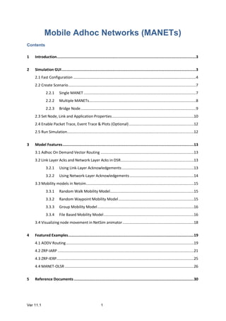
  • 23. Ver 11.1 23 The node A has a datagram to node L. Assume routing zone radius of 2. Since L is not in A's routing zone (which includes B,C,D,E,F,G), A bordercast a routing request to its peripheral nodes: D,F,E, and G. Each one of these peripheral nodes check whether L exists in their routing zones. Since L is not found in any routing zones of these nodes, the nodes bordercast the request to their peripheral nodes. In particular, G bordercasts to K, which realizes that L is in its routing zone and returns the requested route (L-K-G-A) to the query source, namely A. IARP In Zone Routing, the Intrazone Routing Protocol (IARP) proactively maintains routes to destinations within a local neighborhood, which we refer to as a routing zone. More precisely, a node's routing zone is defined as a collection of nodes whose minimum distance in hops from the node in question is no greater than a parameter referred to as the zone radius. Note that each node maintains its own routing zone. An important consequence is that the routing zones of neighboring nodes overlap. An example of a routing zone (for node A) of radius 2 is shown below. Note that in this example nodes B through F are within the routing zone of A. Node G is outside A's routing zone. Also note that E can be reached by two paths from A, one with length 2 hops and one with length 3 hops. Since the minimum is less or equal than 2, E is within A's routing zone.
  • 24. Ver 11.1 24 Peripheral nodes are nodes whose minimum distance to the node in question is equal exactly to the zone radius. Thus, in the above figure, nodes D, F, and E are A's peripheral nodes. The construction of a routing zone requires a node to first know who its neighbors are. A neighbor is defined as a node with whom direct (point-to-point) communication can be established and is, thus, one hop away. Identification of a node's neighbors may be provided directly by the media access control (MAC) protocols, as in the case of polling-based protocols. In other cases, neighbor discovery may be implemented through a separate Neighbor Discovery Protocol (NDP). Such a protocol typically operates through the periodic broadcasting of "hello" beacons. The reception (or quality of reception) of a "hello" beacon can be used to indicate the status of a connection to the beaconing neighbor. Neighbor discovery information is used as a basis for the IARP. IARP can be derived from globally proactive link state routing protocols that provide a complete view of network connectivity. Open NetSim, Select Examples->Mobile-Adhoc-Networks->ZRP-IARP Settings done in the Network: 1. Grid length: 500m*500m 2. Disable TCP in all nodes and disable mobility in all nodes 3. Configure CBR application with default properties 4. Channel characteristics: Path loss only, Path loss model: Log Distance, Path loss exponent: 3 5. Set ZRP routing protocol under network layer properties in all nodes 6. Enable Packet Trace 7. Run simulation for 10 seconds
  • 25. Ver 11.1 25 Output: Open Packet trace and observe Control_Packet_Type/App_Name Users can see only NDP_Hello_Message since the destination node is within the zone. The ZRP framework proactively maintains local routing information (routing zones) based on periodic exchanges of neighbor discovery messages. 4.3 ZRP-IERP Open NetSim, Select Examples->Mobile-Adhoc-Networks->ZRP-IERP
  • 26. Ver 11.1 26 Settings done in the Network: 1. Grid length: 500m*500m 2. Disable TCP in all nodes and disable mobility in all nodes 3. Configure CBR application with default properties 4. Channel characteristics: Path loss only, Path loss model: Log Distance, Path loss exponent: 3.3 5. Set ZRP routing protocol under network layer properties in all nodes 6. Enable Packet Trace 7. Run simulation for 10 seconds Output: Open Packet trace and filter Control_Packet_Type/App_Name to IERP_Route_Request In the above figure, Node-1 is sending IERP_Route_Request packets to its peripheral nodes 4, 5, 7 and 10 since the destination is not present in Node1’s zone. Similarly Node4 transmits IERP_Route_Request packets to its peripheral nodes 2 and 6 and so on. Node7 sends IERP_Route_Reply packet in response to the IERP_Route_Request. And the data packet routes through Node1->Node2->Node10->Node11->Node12. This can be observed in Packet animation also 4.4 MANET-OLSR Optimized Link State Routing Protocol OLSR is developed for mobile ad hoc networks. It operates as a table driven, proactive protocol, i.e., exchanges topology information with other nodes of the network regularly. Each node selects a set of its neighbor nodes as "multipoint relays" (MPR). In OLSR, only nodes,
  • 27. Ver 11.1 27 selected as such MPRs, are responsible for forwarding control traffic, intended for diffusion into the entire network. MPRs provide an efficient mechanism for flooding control traffic by reducing the number of transmissions required. Nodes, selected as MPRs, also have a special responsibility when declaring link state information in the network. Indeed, the only requirement for OLSR to provide shortest path routes to all destinations is that MPR nodes declare link-state information for their MPR selectors. Additional available link-state information may be utilized, e.g., for redundancy. Nodes which have been selected as multipoint relays by some neighbor node(s) announce this information periodically in their control messages. Thereby a node announces to the network, that it has reachability to the nodes which have selected it as an MPR. In route calculation, the MPRs are used to form the route from a given node to any destination in the network. Furthermore, the protocol uses the MPRs to facilitate efficient flooding of control messages in the network. Neighbor detection Neighbor detection populates the neighborhood information base and concerns itself with nodes and node main addresses. The mechanism for neighbor detection is the periodic exchange of HELLO messages. A node maintains a set of neighbor tuples, based on the link tuples. This information is updated according to changes in the Link Set. The Link Set keeps the information about the links, while the Neighbor Set keeps the information about the neighbors. There is a clear association between those two sets, since a node is a neighbor of another node if and only if there is at least one link between the two nodes. The "Originator Address" of a HELLO message is the main address of the node, which has emitted the message. Upon receiving a HELLO message, a node SHOULD first update its Link Set and then update its Neighbor Set Topology discovery The link sensing and neighbor detection part of the protocol basically offers, to each node, a list of neighbors with which it can communicate directly and, in combination with the Packet Format and Forwarding part, an optimized flooding mechanism through MPRs. Based on this, topology information is disseminated through the network. TC message
  • 28. Ver 11.1 28 In order to build the topology information base, each node, which has been selected as MPR, broadcasts Topology Control (TC) messages. TC messages are flooded to all nodes in the network and take advantage of MPRs. MPRs enable a better scalability in the distribution of topology information. The list of addresses can be partial in each TC message (e.g., due to message size limitations, imposed by the network), but parsing of all TC messages describing the advertised link set of a node MUST be complete within a certain refreshing period (TC_INTERVAL). The information diffused in the network by these TC messages will help each node calculate its routing table. When the advertised link set of a node becomes empty, this node SHOULD still send (empty) TC-messages during the duration equal to the "validity time" (typically, this will be equal to TOP_HOLD_TIME) of its previously emitted TC-messages, in order to invalidate the previous TC-messages. It SHOULD then stop sending TC-messages until some node is inserted in its advertised link set. A node MAY transmit additional TC-messages to increase its reactiveness to link failures. When a change to the MPR selector set is detected and this change can be attributed to a link failure, a TC-message SHOULD be transmitted after an interval shorter than TC_INTERVAL. Example: Open NetSim, Select Examples->Mobile-Adhoc-Networks->MANET-OLSR Settings done in the Network: 1. Grid length: 500m*500m 2. Disable TCP in all nodes and disable mobility in all nodes 3. Configure CBR application with default properties
  • 29. Ver 11.1 29 4. Channel characteristics: Path loss only, Path loss model: Log Distance, Path loss exponent: 3 5. Set OLSR routing protocol under network layer properties in all nodes 6. Enable Packet Trace 7. Run simulation for 30 seconds Output: Open Packet trace and filter Control_Packet_Type/App_Name to NDP_HELLO_MESSAGE, Source_ID and Transmitter_ID to Node-1. All the nodes in the network exchange the NDP_HELLO_MESSAGEs periodically (for every 2 seconds- check NETWORK_LAYER_ARRIVAL_TIME column) to detect the neighbours. In the below screenshot, Node-1 is broadcasting NDP_HELLO_MESSAGES to its neighbours 2, 3, 4 and 5 for every 2 seconds Now filter Control_Packet_Type/App_Name to OLSR_TC_MESSAGE, Source_ID and Transmitter_ID to Node-1. All nodes in the network broadcasts Topology Control (TC) messages (for every 5 seconds - check NETWORK_LAYER_ARRIVAL_TIME column) in order to build the topology information base. In the below screenshot, Node-1 is broadcasting OLSR_TC_MESSAGE to its neighbours 2, 3, 4 and 5 for every 5 seconds
  • 30. Ver 11.1 30 5 Reference Documents IEEE 802.11 - 2012 Standard for Wireless LAN OLSR - https://tools.ietf.org/html/rfc3626#section-5 ZRP - https://tools.ietf.org/html/draft-ietf-manet-zone-zrp-04#section-1 ZRP - https://tools.ietf.org/html/draft-ietf-manet-zone-zrp-00 6 Latest FAQs Up to date FAQs on NetSim’s MANET library is available at https://tetcos.freshdesk.com/support/solutions/folders/14000110331