Model Call Girl in Narela Delhi reach out to us at 🔝8264348440🔝
Interlocking concrete pavement for the port
1. Proceedings of the 7th
International Conference on Concrete Block Paving (PAVE AFRICA 2003) 12th
– 15th
October 2003
ISBN Number: 0-958-46091-4 Sun City, South Africa
Proceedings produced by: Document Transformation Technologies Conference Organised by: Conference Planners
INTERLOCKING CONCRETE PAVEMENT FOR THE PORT OF
OAKLAND, CALIFORNIA, BERTHS 55-59
Smith, D.R.
Interlocking Concrete Pavement Institute, 1444 I Street, N.W. Suite 700
Washington, DC 20005 USA. Tel: (202) 712 9036. Fax: (202) 408 0285.
E-mail: dsmith@bostromdc.com
ABSTRACT
Over the past several years, the Port of Oakland, California, expanded its berths and container-
handling facilities with 470,000 m2
of mechanically installed interlocking concrete pavement. The
project is the largest single installation in the western hemisphere and provides a case study for this
paper. It provides an overview of the reasons for selecting concrete pavers, the structural design,
site constraints, and construction. A specific impact to the North American industry was the
development of a specification guide for mechanically installed projects issued by the Interlocking
Concrete Pavement Institute.
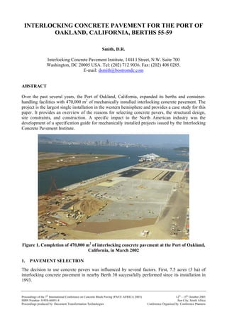
Figure 1. Completion of 470,000 m2
of interlocking concrete pavement at the Port of Oakland,
California, in March 2002
1. PAVEMENT SELECTION
The decision to use concrete pavers was influenced by several factors. First, 7.5 acres (3 ha) of
interlocking concrete pavement in nearby Berth 30 successfully performed since its installation in
1993.
2. This project was the first of a significant size for a west coast port in North America. Presently
operated by Trans Pacific Container Leasing Corporation, the interlocking concrete pavement at
Berth 30 supports shipping containers (transferred by reacher-stackers) and truck chassis storage.
Details on the design and performance of this project are found in Smith, 1996.
The second and strongest factor influencing the decision for concrete pavers was the maximum
flexibility offered by them for container storage layout and operations. At the project’s inception, no
tenants were secured for the five-berth facility envisioned in the Port of Oakland US$600 million
“Vision 2000” master plan. The Vision 2000 plan called for creation of five berths with
reconfiguration and expansion of railroads, wharves, streets, and a new waterfront park on about
450 ha next to the San Francisco Bay. Therefore, complete flexibility was required since a tenant or
tenants could lease any combination of berths and use any combination of straddle carriers, top-pick
trucks, or rubber-tired gantries (RTG).
The first construction phases were on Berths 55/56 with 170,000 m2
of interlocking pavement.
Figure 2 shows the completed phase in use. This phase was followed about a year later with by
paving of 300,000 m2
at adjacent Berths 57/59 as seen underway in Figure 1. The completed facility
simultaneously serves several post-Panamax container ships along a 1,830 m wharf with fast cranes
reaching across 22 containers and loading/unloading 34 per minute. The cranes cleared passing
under the Golden Gate Bridge by a mere 0.6 m on their delivery by ship to Oakland.
Figure 2. The first phases of the paving at Berths 55/56 consisted of
170,000 m2
of concrete pavers.
The third reason for using interlocking concrete pavement was the tenant, Hanjin Shipping,
approached the Port about leasing an area a year into the project planning process. Interlocking
pavers were presented to Hanjin as the preferred option for pavement. Concrete pavers offered
Hanjin flexibility to operate top pick trucks and 8-wheeled, RTG container handling equipment on
containers stacked in any configuration and at different times throughout the year. Hanjin accepted
the pavement and further increased the amount used on the site from a 50% to 50% mix of pavers
and asphalt surface to a 65% to 35% mix of pavers to asphalt. The pavers eliminated the need for
expensive, cast-in-place 1.5 m wide concrete runways typically used under RTGs.
The fourth reason interlocking pavement was used was due to the experience of the design
engineers developed the master plan for the port and design for Berths 55/56 and 57/59.
3. Their initial design experience with interlocking concrete pavers was in the early 1990s with Berth
30. Therefore, past experience provided a confidence level essential for specifying interlocking
concrete (or any other) pavement.
Finally, the soils in the San Francisco Bay are a very fine-grained and have high potential to shift
during an earthquake (liquefaction). With or without assistance from earthquakes, the soil can settle
unevenly, especially after repeated wheel loads from container handling equipment. Concrete
pavers allow a serviceable pavement even with some degree of subgrade movement. Details on the
entire project can be found in the following references, Hoite, 2001; Serventi, 2001; McAneney,
2001; and Johansen, 2001.
2. DESIGN AND CONSTRUCTION
Over 1.5 million m3
of soil dredged from the San Francisco Bay were stockpiled on the site and
used in the grading. Soils dredged from the Bay were monitored for their toxic levels during the fill
process. Most soils remained, while those with unacceptable toxic levels were removed from the
site.
Prior to filling areas behind the wharves with soil, each was covered with a network of geotextile
wick drains. Dredged soil fill settled and de-watered from the surcharge from additional soil placed
over it. After a several months of de-watering and settlement, the soil fill was leveled and
compacted and covered with a 500 mm thick layer of dense-graded, compacted aggregate base. In
specific areas with soft soils, geogrids were used to stabilize the subgrade and lime treatment to
solidify the soils.
The designs utilized layered elastic analysis model called NHELSYM5 a more current version of
ELSYM5 developed by the University of California at Berkeley. The mix of container handling
equipment listed top picks including trailer handling equipment capable of lifting 40,800 kg
container/trailers, 8-wheeled straddle carriers (laden weight: 56,245 kg), and 4 wheeled RTGs
(laden weight: 120,000 kg). Two options were developed for paving over a over a 660 mm thick
compacted aggregate base: one with 125 mm of asphalt and the other with 80 mm thick concrete
pavers and 25 mm of bedding sand. For modeling, 3100 MPa was assumed stiffness for the 100 mm
thick concrete pavers and 25 mm thick bedding sand. The final pavement design was 100 mm thick
concrete pavers, 25 mm thick bedding sand, 75 mm of asphalt, and 450 to 500 mm of compacted
aggregate base. An asphalt base was used due to the inability aggregate bases to provide extended
performance under axle loads of up to 90,000 kg from the top-lift trucks.
With most dredge soils were kept on the site, measures were necessary to help contain leachate
emissions from them. One of the measures used for containing them was capping the soil and
aggregate base with a 75 mm thick asphalt layer. The asphalt cap reduced the potential for leaching
of materials from the soil. Therefore, the asphalt contributed structural capacity while providing a
means to contain leachate. It also reduced the required base thickness saving substantial
hauling/removal costs for the soil.
Materials from many demolished buildings and pavements were crushed and incorporated into the
fill, thereby sparing the expense and air pollution of hauling them offsite. These materials were
from buildings that consisted of a former U.S. Navy base called the Naval Fleet Industrial Supply
Center. This facility was the transfer point for all material and weapons for the U.S. Navy during
World War II. The supply base was sold to the Port of Oakland as part of a national program of
military base closures initiated in the 1990s.
4. Once the 75 mm thick asphalt cap was placed, the 25 mm thick layer of bedding sand was placed
over it using powered sand screeding equipment. The sand was regularly tested for gradation and
degradation. Gradation specified was ASTM C 33 (ASTM, 2001) for concrete sand had almost 0%
passing the 0.075 mm sieve. This was specified to drain any excess water, and not allow the sand to
become saturated and unstable under wheel loads.
Degradation of the bedding sand was tested using the Lilley-Dowson bottle-rolling test (Lilley,
1988). This test procedure assesses the degradation of approximately 0.4 kg sample of dry, sieved
bedding sand subjected to 6 hours of tumbling in a liter-sized ceramic jar with two 75 gram steel
balls. The ability of the sand to resist degradation is assessed by measuring the increase of particles
passing the 0.075, 0.150 and 0.300 mm sieves after tumbling. The degradation test and ASTM C 33
gradation are recommended in the ICPI guide specifications for heavily loaded pavements, and have
been specified in other port and airport pavement projects in North America and elsewhere.
All of the 100 x 200 x 100 mm thick rectangular concrete pavers were manufactured in a
herringbone pattern, stacked, and delivered in 1.3 m2
layers for machine placement. In past port
projects, layer sizes have been typically 1 m2
. The larger layers used at the Port of Oakland yielded
some additional efficiency in installation production. Each layer included for 100 x 100 mm half
pavers. These were not removed but combined into the laying pattern as paving progressed, saving
hauling and disposal costs. Figure 3 shows the stitching of four layers with the placement of half
and whole units.
Figure 3. The stitching pattern for four layers in a herringbone pattern.
Mechanized equipment placed each paver layer at an average daily rate of 500 to 600 m2
per
machine. This production rate includes compacting the concrete pavers, filling the joint sand, and
second compaction of the pavers. The project saw up to seven mechanical installation machines
working at the same time. See Figures 4 and 5. The joints within and among of mechanically placed
paver layers were aligned as shown in Figure 6.
5. Figure 4. Mechanized equipment placing interlocking concrete pavement.
Figure 5. Mechanized equipment placed an average of 500 to 600 m2
of concrete
pavers per machine each day.
6. Figure 6. Straightening joint lines prior to initial compaction.
Figure 7. Detail of pavement edge.
Saw cutting of the paving units fit them against edges, drains, utility structures and other structures
located on the pavement. Figure 7 shows a typical pavement edge. For areas subject to traffic, cut
pavers were no smaller than one-third of a whole paver. Such places included those against drains.
After placing an area of pavers, they were compacted into the bedding sand (Figure 8). Figure 9
shows one sweeper used to spread joint sand across the surface of the pavers. The sand was then
worked into the joints with sweeping and a second compaction with plate compactors (Figure 10).
The joint sand gradation was smaller in size than the bedding sand to facilitate fast entry and filling
of the joints between the pavers. The paver surface was later proof rolled with a large roller to
further seat the units into the bedding sand.
7. Figure 8. Initial compaction of the pavers in the bedding sand was done on large areas at one
time. Note the top-pick container lift trucks being readied in the background.
Figure 9. Spreading joint sand with mounted brooms.
The slope of the pavement is 1% to enable stable stacking of containers. The low slope means water
will be slow draining from the surface. Therefore, a liquid polymer sealer was applied to the surface
in order to attain early stabilization of the joint sand and reduce infiltration of water. The stabilizer
was applied after removal of excess sand from the surface. Re-application of the sealer is not
expected as the sand at the surface of the joints will likely receive sediment and materials from tire
wear to help maintain them in a sealed state.
8. Figure 10. Final compaction of the pavers with sand swept into the joints.
The concrete pavers met the compressive strength requirements, absorption, abrasion, and
dimensional tolerance requirements in ASTM C 936 (ASTM, 2001), the product standard for the
United States. Freeze-thaw testing was not required since Oakland does not see freezing
temperatures. Compressive strengths were maintained at the required average of 55 MPa for the 100
mm thick units.
3. IMPACT ON THE INDUSTRY
A commitment to coordination and quality paving among the manufacturer, paver installation
subcontractor and GC is essential to the success of mechanically installed paving projects.
Coordination has happened informally on many successful mechanically installed projects
throughout North America. Informally means with little written quality control/quality assurance
procedures in the project specifications, expressed as method statements for testing paving materials
and for their installation. In contrast, the Port of Oakland formalized this process by requiring
written quality control/quality assurance procedures jointly agreed upon by the manufacturer,
installer, GC, and the Port. These included systematic testing and measurements during the
manufacture and installation of the paving units, as well as for the bedding and joint sand.
The Interlocking Concrete Pavement Institute has issued a specification guide for mechanical
installation as a result of the development of rigorous quality control/quality assurance
specifications for the Port of Oakland project. The specification guide is for the design community
and potential owners of large paving facilities in North America (Smith, 2003). It formalizes quality
control and quality assurance procedures similar to those found in large-scale asphalt and cast-in-
place concrete paving specifications. The North American interlocking concrete pavement industry
will compete effectively against these pavement systems as it uses the same rigor in specifications,
testing, and inspection for quality control currently done with asphalt and cast-in-place concrete
paving.
4. CONCLUSION
This paper provided a case study on the use of interlocking concrete pavement at the Port of
Oakland. An overview of the reasons for using concrete pavers were provided, as well as general
9. information on design and construction using mechanical installation. As the largest project in
North America, it is expected to encourage greater use of interlocking concrete pavement in port
and industrial facilities. The development of a specification guide by the Interlocking Concrete
Pavement Institute was a major outcome of the Port of Oakland project. This information is
intended to increase the confidence of engineers, port administrators, and tenants who are
considering the use of interlocking concrete pavements in their facility.
5. REFERENCES
ASTM, 2001, C 936, Standard Specification for Solid Interlocking Concrete Paving Units, Annual
Book of Standards, Vol. 04.05, American Society for Testing and Materials, Conshohocken,
Pennsylvania.
ASTM, 2002. C 144 Standard Specification for Aggregate for Masonry Mortar, Annual Book of
Standards, Vol. 04.05, American Society for Testing and Materials, Conshohocken, Pennsylvania.
ASTM, 2002. C 33 Standard Specification for Concrete Aggregates, Annual Book of Standards,
Vol. 04.02, American Society for Testing and Materials, Conshohocken, Pennsylvania.
Hoite, 2001. Berths 57. 58 and 59 Container Wharf at the Port of Oakland, in Proceedings of Ports
2001 Conference, Norfolk, Virginia, American Society of Civil Engineers, Reston, Virginia.
Johansen, 2001. Facilities Master Planning and Design – Vision 2002, Port of Oakland, in
Proceedings of Ports 2001 Conference, Norfolk, Virginia, American Society of Civil Engineers,
Reston, Virginia.
Lilley, A., 1988. “ Laying Course for Concrete Block Paving,” in Proceedings of the 3rd
International Conference on Concrete Block Paving, Rome, Italy, Pavitalia, pp. 457-462.
McAneny, D., 2001. Naval Base to Container Terminal Conversion: The Smallest 500 Acres You
Have Ever Seen, in Proceedings of Ports 2001 Conference, Norfolk, Virginia, American Society of
Civil Engineers, Reston, Virginia.
Serventi, J., 2001. The Port of Oakland’s Vision 2002 Development – Meeting Customers Needs
Through the Redevelopment of a Former Naval Facility and Railyard in to a Modern Marine
Terminal Complex, in Proceedings of Ports 2001 Conference, Norfolk, Virginia, American Society
of Civil Engineers, Reston, Virginia.
Smith, D. R., 2003. “A Specification Guide for Construction of Mechanically Installed Interlocking
Concrete Pavements,” in Proceedings of the 7th
International Conference on Concrete Block Paving,
Sun City, South Africa, Concrete Manufacturers Association of South Africa.
Smith, D. R., 1996. “Achieving Excellence – Lessons from Recent Port and Airport Projects in
America,” in Proceedings of the 5th
International Conference on Concrete Block Paving, pages 511-
531, Pave Israel, Dan Knassim, Ltd., Ramat-Gan, Israel.
10. INTERLOCKING CONCRETE PAVEMENT FOR THE PORT OF
OAKLAND, CALIFORNIA, BERTHS 55-59
Smith, D.R.
Interlocking Concrete Pavement Institute, 1444 I Street, N.W. Suite 700
Washington, DC 20005 USA, Tel: (202) 712 9036. Fax: (202) 408 0285.
E-mail: dsmith@bostromdc.com
Biography
David R. Smith
MUPRL, ASCE, CSI, ASLA
With an architecture, engineering, and environmental planning background, David R. Smith has
been involved with segmental concrete pavement since 1977. He has been working in the industry
and for institutionalization of segmental concrete paving in North America since 1987. With many
companies, he launched the Interlocking Concrete Pavement Institute (ICPI) in 1993. He has
authored scores of magazine articles, brochures, and technical bulletins, technical papers, and
promotional brochures for the ICPI.
His work includes co-authorship of ICPI technical manuals, Port and Industrial Pavement Design
with Concrete Pavements and Airfield Pavement Design with Concrete Pavers. He has authored the
ICPI Concrete Paver Installation Contractor Certification Course and Permeable Interlocking
Concrete Pavements. David R. Smith is editor of the Interlocking Concrete Pavement Magazine, a
quarterly publication featuring unique projects that circulates to thousands of designers and
contractors. He also authored the design idea book, Patio, Driveway and Plazas—The Pattern
Language of Concrete Pavers.
As a leading authority in North America on concrete segmental paving, Mr. Smith regularly speaks
at national and international conferences. He is secretary-treasurer of the Small Element Paving
Technologists. He is an active member of ASTM Committee C 27.20 on Architectural Precast
Products, having written and revised product several standards on segmental concrete paving
products for that organization. He is participates as a member in the American Society of Civil
Engineers, American Public Works Association, Construction Specifications Institute, and the
American Society of Landscape Architects. Mr. Smith has contributed continuing education
programs to the American Society of Landscape Architects and to the American Institute of
Architects.
His education includes a bachelor of Architecture and a masters of Urban and Regional Planning
(environmental concentration) from Virginia Tech in Blacksburg, Virginia. As ICPI’s Technical
Director, he works daily with design professionals, contractors, and homeowners on the design,
specification, construction, and maintenance of segmental concrete pavements.