(2010) - Yates M, Krzeminski M, Berthier D, Hamidi B - The Application of Jet Grouting for the Construction of Sydney International Airport Runway End Safety Area
Similar to (2010) - Yates M, Krzeminski M, Berthier D, Hamidi B - The Application of Jet Grouting for the Construction of Sydney International Airport Runway End Safety Area
Similar to (2010) - Yates M, Krzeminski M, Berthier D, Hamidi B - The Application of Jet Grouting for the Construction of Sydney International Airport Runway End Safety Area (20)
(2010) - Yates M, Krzeminski M, Berthier D, Hamidi B - The Application of Jet Grouting for the Construction of Sydney International Airport Runway End Safety Area
1. THE APPLICATION OF JET GROUTING FOR THE CONSTRUCTION OF
SYDNEY INTERNATIONAL AIRPORT RUNWAY END SAFETY AREA
Babak Hamidi(1)
, Michal Krzeminski(1)
, Daniel Berthier(1)
, Philippe Vincent(1)
, Murray Yates(1)
(1)
Menard Bachy
ABSTRACT
The Runway End Safety Area (RESA) is part of the upgrade plan of the Sydney International Airport and adds an extension
to the end of the runway. As this area passes a number of existing facilities it will have to be bridged over a heritage listed
sewer, an airport perimeter road and the existing highway road.
The area of RESA was previously low lying farming land with major alterations in the ground contours due to previous
construction works. The site is on man-made filling up to 4 m thick from earlier dredging works and predominantly marine
originated alluvium. Also soft mud deposits are extensively spread over the area, and groundwater level is quite high.
The loads introduced by bridging RESA over existing structures and lowering the road level at the intersection with RESA
required specific geotechnical measures.
Jet Grouting has been used successfully in RESA with multiple purposes such as increasing the ground’s bearing, retaining
the ground and creating impermeable barriers to cut off the flow of water during construction. Multiple requirements and
variations in ground conditions required a detailed design with a number of Jet Grout column diameters, lengths and
combinations. Design included finite element analyses using Plaxis and later verified by sampling of grout and installing
inclinometers to measure ground deformations.
1. INTRODUCTION
As part of the upgrade programme of Sydney Airport, the end of Runway 07/25 is being extended for aircraft emergency
overrun to achieve compliance with new international safety requirements. The new Runway End Safety Area (RESA)
project is being built in a location that collides with the heritage listed Southern and Western Suburbs Ocean Outfall Sewer
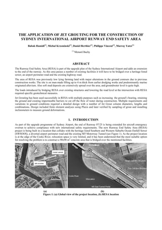
(SWSOOS), a diverted airport perimeter road and the existing M5 Motorway Tunnel (see Figure 1). As the project location
is at the edge of the Cooks River, relocation space is very limited, and it has been understood that the most suitable option
for resolving the problem is to construct a 90x90 m2
concrete area that is bridged over the mentioned facilities.
(a) (b)
Figure 1: (a) Global view of the project location, (b) RESA location
2. Levels at the end of the runway are generally around +5 to +6 m RL. Top of SWSOOS is approximately at +6 m RL. The
perimeter road is approximately at +1.5 m RL except where it passes under the sewer, at which point it is at -2.6 m RL.
RESA is being constructed on the eastern bank of the Cooks River. This area has been altered several times by SWSOOS
construction in the 1950s. It would appear from early aerial photographs that the area of RESA was previously low lying
farming land and that it has been extensively filled during the development of the airport, particularly for the 07/25 runway
construction. Photographs taken during construction of the SWSOOS seem to confirm that there have been some major
alterations in ground contours to the east of SWSOOS and more recently for the underpass, perimeter road and M5
Motorway tunnel construction.
The bridge overrun will consist of a conventional pavement from the end of the runway and then a bridge structure. The
structure will span over SWSOOS, the new perimeter road and M5 tunnel.
In addition to the bridge, the project will include lowering and relocating the existing perimeter road so that there is at least
a 5 m clearance underneath the proposed aircraft bridge. The minimum design levels shown on the perimeter road
longitudinal section indicated that excavation was needed to enable pavement construction to be undertaken.
The first stage of the works comprised of a shallow excavation beneath SWSOOS, whilst it remained supported on its old
foundations of driven concrete piles, in order to facilitate the installation of the underpinning prestressed concrete structure.
The ground had to provide sufficient bearing to support the formwork of this structure before the load was transferred to
four external large bored piles and the old SWSOOS piles were removed. The sewer will be a triple cell reinforced concrete
box structure supported on piles which are also required to carry part of the load from the bridge structure.
Temporary works required the construction of a cofferdam system to prevent water ingress and to provide ground retention
around the underpass structure.
Figure 2: Ground profile at RESA
3. 1.1. GROUND CONDITIONS
At the time of the commencement of RESA, the soil strata comprised of up to 4 m of fill, reclaimed during earlier dredging
works, followed by predominantly alluvium of marine origin. The subsoil below sea level consisted of soft clay deposits, 8
m thick, overlying 2 m of sand and underlain by stiff residual clay.
A typical section of the ground is shown in Figure 2. Ground surface is from about +3.5 to +1 m RL. Fill layer was
composed of a variation of loose to dense sand and silty sand extending down approximately to elevation -1.5 m RL. This
layer was followed by soft to firm clay or very loose silty sand down to about -8 m RL. CPT cone resistance, qc, of this
layer was less than 1 MPa. Sleeve friction ratio, fr, was generally about 4% with low and high values of 2% and 6%
respectively. The fine layer was underlain by a 2 m thick layer of dense sand that extended down to -10 m RL. qc of this
layer ranged from 25 to 35 MPa. The soil from -10 to -16 m RL was stiff or very stiff clay. Cone resistance was around 3 to
4 MPa and occasionally higher. Friction ratio was as high as 8%. The soil in between the mentioned layer and bedrock at
about -20 m RL was once again dense sand with qc in the range of 25 to 35 MPa. In turn bedrock was medium to high
strength sandstone.
The available information for this site indicated that groundwater levels were at about RL +1.0 m and fluctuating with the
tides of the sea. These levels could have risen during periods of heavy rainfall due to substantial infiltration into the exposed
soils between the 07/25 Runway and the International Terminal.
1.2. GEOTECHNICAL REQUIREMENTS
In order to span the land bridge over SWSOOS, the M5 Tunnel, and the widened and realigned airport perimeter road it
was necessary to identify and implement geotechnical solutions for
• Providing a water cut-off system to allow construction within the working perimeter.
• Allowing construction and excavation under SWSOOS with sufficient head room for positioning equipment under
SWSOOS (first excavation to elevation ±0 m RL).
• Providing bearing for the formwork and temporary false work props of the new support structure that would
replace the piles that were originally supporting SWSOOS.
• Providing sound working platform to build the underpass bottom slab.
• Ensuring full lateral support to the sides of the first and second excavations. The second excavation was at the
depth of -3.6 m RL at the bottom slab and -5.5 m RL at drainage facilites. Horizontal movement had to be limited
to 10 mm in normal working conditions and 11 mm for accidental failure of the dewatering system and the rise of
groundwater level outside the cut-off area from -1 to +1 m RL.
• Providing the temporary wall and foundation system of the new pumping station and drainage lines.
• Stabilising the soft clay ground on the north and south sides of the perimeter wall to facilitate construction of the
underpass bottom slab.
Figure 3: Jet Grouting systems
4. 2. SOLUTION: JET GROUTING
Baulderstone, the projects managing contractor, awarded Menard Bachy the specialist geotechnical works to resolve the
mentioned problems. Jet Grouting (JG) was proposed and utilized for providing the solution to all the requirements
previously stated. As reported by Mitchell (1981) jet grouting was first introduced in Japan (Yahiro and Yoshida, 1973;
Miki, 1973; Miki et al., 1980).
Jet grout columns are installed by initially drilling a small hole, typically 100 mm in diameter to the required depth. Then
the soil is eroded by a high pressure jet of grout, water, or air-enshrouded grout or water, and the simultaneous injection of
cement suspension grout into the disturbed soil by means of a nozzle. The injection pressure can be up to 60 MPa. The drill
stem and nozzle are simultaneously raised and rotated so as to combine the grout with a portion of the original soil to form
solidified soil mixed material. The end product is cementitious round columns.
There are three major systems for jet grouting; i.e. the single, double and triple fluid systems. In the single fluid system a
special hollow drill rod which is equipped with a monitor containing a horizontal jet nozzle at the tip is lowered into the
hole. Cement suspension grout is pumped down the drill rod at a very high pressure of up to 60 MPa while the drill rod and
monitor are simultaneously rotated and withdrawn. The grout that exits the jet nozzles at high velocity disintegrates the soil
and mixes with it to form soilcrete. In the double fluid system the grout is encased within a shroud of compressed air. The
air acts as a buffer between the groundwater and the grout, greatly increasing the cutting efficiency. It also creates
turbulence in the waste spoil, improving the efficiency of its removal. In this method a special coaxial drill string and jet
monitor are used The triple fluid system requires a triaxial drill stem and monitor with appropriate nozzles. In this system an
air-enshrouded jet of water erodes the soil while the grout is simultaneously injected through separate nozzles. The cutting
jets are located above the grout supply, which allows a nearly complete replacement of the soil with grout as the monitor is
withdrawn. The three grouting systems are shown schematically in Figure 3.
Jet grout columns can be constructed in all soils; however the effective radius and strength depends on the properties of the
soil and the jet grouting parameters used. In granular soils jet grout columns can have a strength of about 10 to 15 MPa or
more; however the strength of jet grouted columns in clay can be quite less and as low as 1 MPa. Jet grout strength is
primarily determined by the soil type; however the amount of cement used per unit volume and the water-cement ratio also
have an effect. Typical water-cement grouts have a water-cement ratio in the range of about 0.6 to 1.2 by weight.
For single fluid system jet grouted columns, typically diameters are on the order of 0.4 to 0.6 m in cohesive soils and up to
about 1.2 m in granular materials. In two-fluid system column diameters are on the order of 0.8 to 1.2 m in cohesive soils
and up to about 1.8 m in granular soils. Implementation of the triple fluid system allows the construction of larger diameter
columns whereas in cohesive and granular soils the diameters can be respectively up to 1.5 m and 3.6 m. Typical injection
parameters for different jet grouting systems are shown in Table 1.
2.1. DESIGN
A complex system of JG columns were designed with different diameters, spacings, lengths and reinforcement to satisfy the
various project requirements from the necessity to provide bearing to creating stable and impervious boundaries. The
complex construction drawing of the JG columns under SWSOOS is shown in Figure 4.
Jet Grouting System Single fluid Double fluid Triple fluid
Grout injection rate (l/min) 40-115 70-130 70-130
Grout pressure (MPa) 20-60 30-60 3-17
Air flow (l/min) - 3700-6000 2700-6000
Air pressure (MPa) - 0.6-1.2 0.6-1.2
Water flow (l/min) - - 70-150
Water pressure (MPa) - - 20-50
Rotation (RPM) 10-25 5-10 2-10
Withdrawal rate (cm/min) 10-50 7-30 5-30
Table 1: Typical injection parameters for different jet grouting systems
5.
Figure 4: Complex layout of JG columns under SWSOOS
Numerical analyses using Plaxis was carried out to verify that stresses within the JG columns and ground deformations
would remain within acceptable limits.
In the calculations multiple groundwater levels had to be assumed. Groundwater level at the periphery of the project was
assumed to be reduced by dewatering and pumping to -1 m RL during execution of jet grouting. Inside the perimeter cut-
off, water level was assumed to be to be 1.0m below existing excavation level and at -6.5 m RL when proceeding to final
excavation. Also, for the accidental condition of failure of the dewatering system, groundwater level at the periphery was
assumed to be +1 m RL.
The toes of the JG columns of the perimeter wall were anchored 1 m into the stiff to very stiff clay layer in order to provide
water cutt-off. Thus the longest JG columns were 13 m in length.
Jet grout column properties for calculation purposes were determined by preparing a number of different grout mixes in the
laboratory for sandy, silty and clayey soil. Based on these tests and by applying a reduction factor of 3 which incorporated
the differences between lab and site mixes and long term creep behaviour, Young Modulus of the JG columns was
conservatively taken as 1,800 MPa.
In the finite element model, JG columns were represented by a wall with a thickness based on equivalent axial stiffness
(Hamidi et al, 2009).
It is noted that the mass improvement of the soil by the short JG columns had a substantial effect on reducing the perimeter
wall’s horizontal movements to approximately 10 mm at the toe which were below acceptance criterion. The effect of these
crucial components of design were taken into account by modifying the ground properties based on the density of the
columns, respectively 41 and 75% in different locations.
6.
Figure 5: Finite element analysis for verification of stresses and deformations
Structural verification of the perimeter wall jet grout columns was carried out for two main failure modes; i.e. overstressing
due to bending moment and failure due to shear. Based on these calculations a steel bars were used for reinforcing the JG
columns of the perimeter cut-off wall.
In order to be able to assess the ground conditions during any stage of the works, a typical finite element analysis for any
cross section included a number of calculation phases. As an example, the below phases were considered for the eastern
section of the wall:
• Initial stage: This phase was modelling the project prior to commencement of any works with groundwater level at
+1 m RL.
• Initial excavation stage: At this phase the groundwater level was reduced to -1 m RL and the working platform
level was lowered (excavated) to ±0 m RL.
• Installing the JG columns: The JG wall was modelled to -11 m RL, and the JG elements were modelled between
the perimeter walls. The purpose of the JG mass improvement network was to reduce the perimeter wall
movement.
• First excavation stage: In this phase of modelling, the ground water level within the perimeter wall was reduced to
-8 m RL. Excavation was modelled to -1.5 m RL. Groundwater flow boundary condition calculations was
introduced to the model during this phase. A groundwater flow calculations were carried out in order to model
ground water pressures for this phase.
• Second excavation stage: In this phase the excavation was modelled to be at -3.6 m RL.
• Third excavation stage: The sewer pit excavation to -5.5 m RL was modelled in this phase. The model and ground
deformations of this phase can be seen in Figure 5.
• Accidental water rise: In this phase the accidental failure of the dewatering system and rising of the groundwater
level outside of the perimeter wall to +1 m RL were analysed.
7. Figure 5: Implementation of a special mini rig for low head areas
• Global stability failure calculation: c –φ reduction calculation using Plaxis was carried out to check the stability of
the excavation. Calculation demonstrated that the factor of safety for the top of the slope (area outside of the
perimeter wall) was at least 1.90. The excavation’s slip line factor of safety was even higher than this figure.
2.2. CONSTRUCTION
Based on the design, a minimum UCS of 4 MPa at 28 days 1,628 JG columns with a total drilling length of 13,761 m,
columns length of 6,368 m and volume of 5,134 m3
were installed using the double fluid system sometimes preceded by
pre-cutting to allow larger diameter columns. Of this, approximately 500 JG columns were installed under SWSOOS and in
between its supporting piles. JG column diameters were variable from a minimum of 1 m to a maximum value of 2.5 m.
Minimum and maximum column lengths were respectively from 2 to 13 m, with perimeter support columns reinforced with
one N36 bar in the centres.
Potable water and marine grade cement were used in the JG columns. A total of 5,104 tons of cement was used to produce
the columns.
The works were carried out using 3 rigs in two working shifts. As shown in Figure 6, one of these rigs was a specially
designed machine capable of working underneath SWSOOS with a limited head room of only 2.7 m. An interval in jet
grouting operations was allowed during the construction of RESA to allow for the first excavation, construction of the
SWSOOS frame support and cutting SWSOOS’ redundant piles.
In order to ensure minimum effect of jet grouting on the piles of SWSOOS, a clearance distance of 500 mm and 800 mm
were respectively considered for the short and long JG columns.
Due to the sensitivity of the project, variations in ground levels, and head and toe elevations of JG columns it was necessary
to implement a very stringent surveying method on site that would minimize errors. Thus, the installation point of each JG
column and actual ground levels was identified using a GPS system that was capable of reporting all three coordinates of
the points.
Both drilling and jetting were monitored by digital recording hardware. During drilling, depth, advance speed, rotary speed
and thrust pressure were recorded. Grout pressure, grout flow, grout volume, stationary time, air pressure, air flow, uplift
speed and rotation speed were monitored during the jetting phase. The start and stop time for each columns was also
recorded. Furthermore, the grout density and viscosity were measured during each working shift.
Special sequences were applied to the columns to allow sufficient setting time of the grout as needed.
In addition to collecting spoil samples, 0.5% of the columns were cored between the overlapping interface of two columns
and samples collected for testing. The tests demonstrated that the minimum required UCS of 4MPa had been achieved.
8. Figure 6: Excavation and construction of SWSOOS support structure after jet grouting
Actual measurements during construction confirmed that horizontal deformations were at most 2 mm at the top of the JG
perimeter wall which was well below the acceptance limit. Settlement of the frame support was measured to be 8 mm which
was very close to the calculated value of 9 mm.
These highly demanding jet grouting works, tightly nested with other construction activities, were carried out in two main
stages; namely before and after installation of SWSOOS supporting structure. Figure 6 shows the excavation and retainment
of the ground and construction of SWSOOS’ support structure after jet grouting.
3. CONCLUSION
RESA has been a high performance design and construction feat in ground improvement. This project has demonstrated the
successful application of jet grouting for multiple purposes and functions. Stringent requirements, limited movements in the
sensitive SWSOOS structure and the piles supporting it to a few millimetres, complex staging, difficult ground conditions
and a number of site constraints dictated a very comprehensive design supported by finite element analyses. Using jet
grouting technology it has possible to create an impervious barrier to allow excavation under groundwater level. The same
barrier was also designed as a wall to retain the soil from entering the work area. Also, JG columns were able to improve the
ground soil as a mass in order to minimize wall deformations. JG columns also provided bearing for loads and formed the
foundation of SWSOOS’ frame support.
4. REFERENCES
HAMIDI, B., NIKRAZ, H. & VARAKSIN, S. (2009) Arching in Ground Improvement. Australian Geomechanics Journal,
44, 4 (December), 99-108.
MIKI, G. (1973) Chemical Stabilization of Sandy Soils by Grouting in Japan. 8th International Conference on Soil
Mechanics and Foundation Engineering, 395.
MIKI, G., NAKANISHI, W., IIZUKA, T., ICHINO, Y. & IMAMISHI, H. (1980) Grout Jetting Method Applied to
Excavation of Soft Ground.
MITCHELL, J. K. (1981) Soil Improvement State-of-the-Art Report. 10th International Conference on Soil Mechanics and
Foundation Engineering, 4, Stockholm, 509-565.
YAHIRO, T. & YOSHIDA, H. (1973) Induction Grouting Method Utilizing High Speed Water Jet. 8th International
Conference on Soil Mechanics and Foundation Engineering, Moscow, 402-404-404 also 359-362.