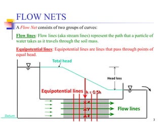
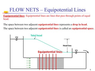
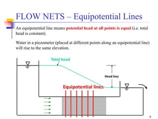
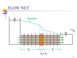
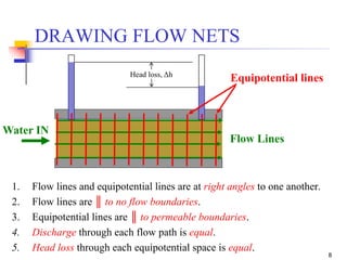
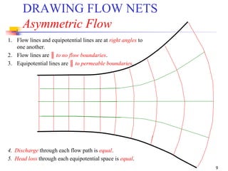
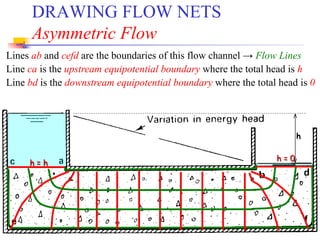
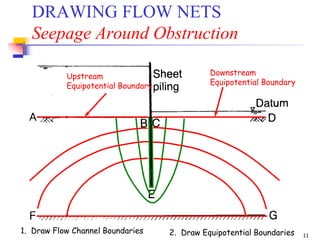
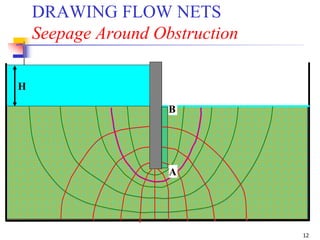
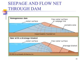
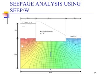
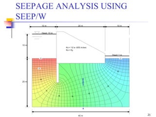
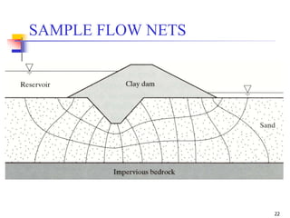
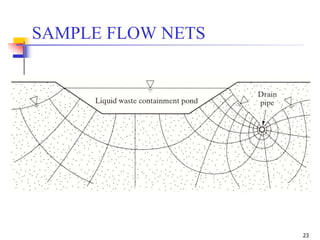
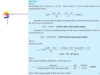
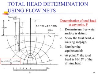
The document discusses geotechnical engineering principles focusing on water flow through soils, including the determination of hydraulic conductivity (k) and hydraulic gradient (i) through laboratory and field tests. It elaborates on flow nets, comprising flow lines and equipotential lines, and emphasizes their significance in analyzing seepage and fluid behavior in soil. The content is aimed at undergraduate civil engineering students and provides practical examples and rules for constructing flow nets.
![1
Geotechnical Engineering–I [CE-221]
BSc Civil Engineering – 4th Semester
by
Dr. Muhammad Irfan
Assistant Professor
Civil Engg. Dept. – UET Lahore
Email: mirfan1@msn.com
Lecture Handouts: https://groups.google.com/d/forum/2016session-geotech-i
Lecture # 27
3-May-2018](https://image.slidesharecdn.com/27-180924141458/85/Geotechnical-Engineering-I-Lec-27-Flow-Nets-1-320.jpg)
![2
WATER FLOW THROUGH SOILS
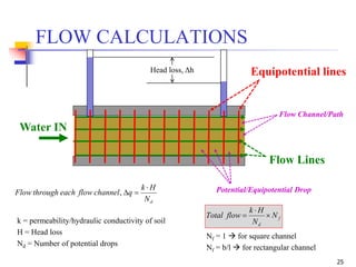
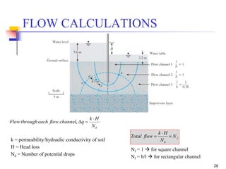
To determine the quantity of flow, two parameters are needed
* k = hydraulic conductivity
* i = hydraulic gradient
Determination of ‘k’
1- Laboratory Testing [constant head test & falling head test]
2- Field Testing [constant/falling head tests, pump out tests, etc]
3- Empirical Equations
Determination of ‘i’
1- From the head loss and geometry
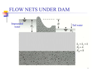
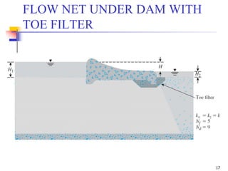
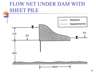
2- Flow Nets
(how permeable is the soil medium)
(how large is the driving head)
Today’s
discussion
A
h
kAikq
L](https://image.slidesharecdn.com/27-180924141458/85/Geotechnical-Engineering-I-Lec-27-Flow-Nets-2-320.jpg)

![Geotechnical Engineering-I [Lec #23: Soil Permeability]](https://cdn.slidesharecdn.com/ss_thumbnails/23-180924141141-thumbnail.jpg?width=640&height=640&fit=bounds)

![Geotechnical Engineering-I [Lec #24: Soil Permeability - II]](https://cdn.slidesharecdn.com/ss_thumbnails/24-180924141149-thumbnail.jpg?width=640&height=640&fit=bounds)
![Geotechnical Engineering-I [Lec #26: Permeability thru Stratified Soils]](https://cdn.slidesharecdn.com/ss_thumbnails/26-180924141352-thumbnail.jpg?width=640&height=640&fit=bounds)

![Geotechnical Engineering-I [Lec #13: Soil Compaction]](https://cdn.slidesharecdn.com/ss_thumbnails/13-180923184035-thumbnail.jpg?width=640&height=640&fit=bounds)
![Geotechnical Engineering-II [Lec #6: Stress Distribution in Soil]](https://cdn.slidesharecdn.com/ss_thumbnails/6-180930132732-thumbnail.jpg?width=640&height=640&fit=bounds)
![Geotechnical Engineering-II [Lec #23: Rankine Earth Pressure Theory]](https://cdn.slidesharecdn.com/ss_thumbnails/23-181123050516-thumbnail.jpg?width=640&height=640&fit=bounds)


![Geotechnical Engineering-I [Lec #17: Consolidation]](https://cdn.slidesharecdn.com/ss_thumbnails/17-180924140731-thumbnail.jpg?width=640&height=640&fit=bounds)


![Geotechnical Engineering-II [Lec #11: Settlement Computation]](https://cdn.slidesharecdn.com/ss_thumbnails/11-181020124840-thumbnail.jpg?width=640&height=640&fit=bounds)


![Geotechnical Engineering-I [Lec #27A: Flow Calculation From Flow Nets]](https://cdn.slidesharecdn.com/ss_thumbnails/27-180924141501-thumbnail.jpg?width=640&height=640&fit=bounds)


![Geotechnical Engineering-II [Lec #28: Finite Slope Stability Analysis]](https://cdn.slidesharecdn.com/ss_thumbnails/28-181125070402-thumbnail.jpg?width=640&height=640&fit=bounds)
![Geotechnical Engineering-II [Lec #26: Slope Stability]](https://cdn.slidesharecdn.com/ss_thumbnails/26-181125070353-thumbnail.jpg?width=640&height=640&fit=bounds)
![Geotechnical Engineering-II [Lec #27: Infinite Slope Stability Analysis]](https://cdn.slidesharecdn.com/ss_thumbnails/27-181125070251-thumbnail.jpg?width=640&height=640&fit=bounds)
![Geotechnical Engineering-II [Lec #25: Coulomb EP Theory - Numericals]](https://cdn.slidesharecdn.com/ss_thumbnails/25-181123050611-thumbnail.jpg?width=640&height=640&fit=bounds)
![Geotechnical Engineering-II [Lec #24: Coulomb EP Theory]](https://cdn.slidesharecdn.com/ss_thumbnails/24-181123050536-thumbnail.jpg?width=640&height=640&fit=bounds)
![Geotechnical Engineering-II [Lec #22: Earth Pressure at Rest]](https://cdn.slidesharecdn.com/ss_thumbnails/22-181123050434-thumbnail.jpg?width=640&height=640&fit=bounds)


![Geotechnical Engineering-II [Lec #19: General Bearing Capacity Equation]](https://cdn.slidesharecdn.com/ss_thumbnails/19-181123045917-thumbnail.jpg?width=640&height=640&fit=bounds)
![Geotechnical Engineering-II [Lec #18: Terzaghi Bearing Capacity Equation]](https://cdn.slidesharecdn.com/ss_thumbnails/18-181123045854-thumbnail.jpg?width=640&height=640&fit=bounds)
![Geotechnical Engineering-II [Lec #17: Bearing Capacity of Soil]](https://cdn.slidesharecdn.com/ss_thumbnails/17-181123045836-thumbnail.jpg?width=640&height=640&fit=bounds)
![Geotechnical Engineering-II [Lec #15 & 16: Schmertmann Method]](https://cdn.slidesharecdn.com/ss_thumbnails/15-181020124920-thumbnail.jpg?width=640&height=640&fit=bounds)
![Geotechnical Engineering-II [Lec #14: Timoshenko & Goodier Method]](https://cdn.slidesharecdn.com/ss_thumbnails/14-181020124917-thumbnail.jpg?width=640&height=640&fit=bounds)
![Geotechnical Engineering-II [Lec #13: Elastic Settlements]](https://cdn.slidesharecdn.com/ss_thumbnails/13-181020124852-thumbnail.jpg?width=640&height=640&fit=bounds)
![Geotechnical Engineering-II [Lec #12: Consolidation Settlement Computation]](https://cdn.slidesharecdn.com/ss_thumbnails/12-181020124845-thumbnail.jpg?width=640&height=640&fit=bounds)
![Geotechnical Engineering-II [Lec #9+10: Westergaard Theory]](https://cdn.slidesharecdn.com/ss_thumbnails/9-181020124827-thumbnail.jpg?width=640&height=640&fit=bounds)
![Geotechnical Engineering-II [Lec #8: Boussinesq Method - Rectangular Areas]](https://cdn.slidesharecdn.com/ss_thumbnails/8-181020124822-thumbnail.jpg?width=640&height=640&fit=bounds)
![Geotechnical Engineering-II [Lec #7A: Boussinesq Method]](https://cdn.slidesharecdn.com/ss_thumbnails/7a-181020124807-thumbnail.jpg?width=640&height=640&fit=bounds)
![Geotechnical Engineering-II [Lec #7: Soil Stresses due to External Load]](https://cdn.slidesharecdn.com/ss_thumbnails/7-180930132739-thumbnail.jpg?width=640&height=640&fit=bounds)
![Geotechnical Engineering-II [Lec #5: Triaxial Compression Test]](https://cdn.slidesharecdn.com/ss_thumbnails/5-180930132716-thumbnail.jpg?width=640&height=640&fit=bounds)


