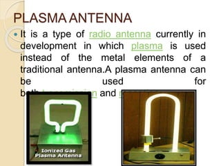
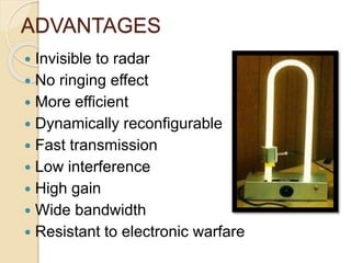
BY,
S . SWETHA -
14251A1744
K . VYSHNAVI -
14251A1730
ANTENNA
 Antenna is a metallic structure
used to propagate EM
wave such that maximum
intensity is in intended
direction.
 It is an electromagnetic radiator,
transducer, sensor and impedance
matching device
 used in systems such as radio
broadcasting , broadcast television, radar
etc.
What is ‘PLASMA’?
 Fourth state of matter
 Plasma can be defined as a set of quasi-
neutral particles with free electric charge
carriers which behave collectively
LIGHTENING
NEON LIGHTS
PLASMA ANTENNA
 It is a type of radio antenna currently in
development in which plasma is used
instead of the metal elements of a
traditional antenna.A plasma antenna can
be used for
both transmission and reception.
• Plasma antenna technology employs ionized gas
enclosed in a tube (or other enclosure) as the
conducting element of an antenna
• Plasma antennae can be configured to operate up
to 20GHz.
• Plasma allows radio frequency signals to be
transmitted or received as ionized gas is an
efficient conducting element.
• If W > Wp. EM wave frequency is greater than
plasma frequency (an inherent property of plasma),
so wave propagates in plasma and the plasma has
dielectric properties which are electrically
controllable.
• If W < Wp. The wave is vanishing with the plasma
medium. The wave can be absorbed or reflected
depending on the collision frequency.
• The Nyquist formula states that the noise power is
proportional to temperature However, the Nyquest
formula assumes that the electron collision rate is much
higher than the applied frequency.
𝜋
2
RKT
• This is not always true in a plasma. If the collision rate
is smaller that the applied frequency, the noise in this
frequency range is greatly reduced.
𝜋
2
𝟏
(𝟏+
𝟐𝝅𝒗
𝒗 𝒄
𝟐)
Thermal noise in plasma antenna……
Methods of producing radiations:
There are two methods of producing
radiation:
 m-radiation method
 d-radiation method
Specifications Traditional Antenna Plasma Antenna
Construction Metal Plasma
Power Lower Higher
Efficiency Low High
Weight Higher Lower
Size Large Small
Ringing Effect Yes No
Transmission/Reception
Uses RF sinusoidal
signals
Uses short pulse during
the time of
transmission/reception
Noise Higher
Lower, plasma antenna
has low collision rates
among its charge carriers.
Comparision of radiation patterns:
 Block diagram of simple monopole plasma antenna
Directivity comparision at 1GHz
Gain comparision at 1GHz
ADVANTAGES
 Invisible to radar
 No ringing effect
 More efficient
 Dynamically reconfigurable
 Fast transmission
 Low interference
 High gain
 Wide bandwidth
 Resistant to electronic warfare
DISADVANTAGES
 Complex Design
 More power consumption
 Always stable and repeatable plasma
volumes are required
 Cost required for ionising plasma is
more
 Maintenance to repair or replace the
unit components will be high
APPLICATIONS
 Radio and television broadcasting
 Space communications
 Military applications
 Faster internet
 Public safety networks
AVAILABLE
 Available
Plasma Sonics Ltd. Co.
 Specifications
Glass -Pyrex
Tube Length > 3
Tube Diameter -25mm
Mount Dimensions-
12.5 inches X 21 inches
 Price: $ 380
CONCLUSION
 Technology Currently being under
development
 Could greatly impact future of
communications
 Better performance than
metal antennas
REFERENCES
 Journals and websites
 [1]Kumar, Rajneesh; Bora, Dhiraj; , "A reconfigurable plasma
antenna,"Journal of Applied Physics, vol.107, no.5,
pp.053303-053303-9, Mar 2010
 [2] Xue-Shi Li; Fan Luo; Bin-Jie Hu; , "FDTD Analysis of
Radiation Performance of a Cylinder Plasma Antenna,"
Antennas and Wireless Propagation Letters, IEEE, vol.8, no.,
pp.756-758, 2009 doi: 10.1109/LAWP.2009.2022963
 http://www.plasmas.org/what-are-plasmas.htm
 http://www.essortment.com/plasma-fourth-state-matter-
40444.html
 http://intuitor.com/resonance/radioTVres.html
 http://www.plasmasonics.com/tube.html
Plasma Antenna and its applications

Plasma Antenna and its applications

  • 1.
    BY, S . SWETHA- 14251A1744 K . VYSHNAVI - 14251A1730
  • 2.
    ANTENNA  Antenna isa metallic structure used to propagate EM wave such that maximum intensity is in intended direction.  It is an electromagnetic radiator, transducer, sensor and impedance matching device  used in systems such as radio broadcasting , broadcast television, radar etc.
  • 3.
    What is ‘PLASMA’? Fourth state of matter  Plasma can be defined as a set of quasi- neutral particles with free electric charge carriers which behave collectively LIGHTENING NEON LIGHTS
  • 4.
    PLASMA ANTENNA  Itis a type of radio antenna currently in development in which plasma is used instead of the metal elements of a traditional antenna.A plasma antenna can be used for both transmission and reception.
  • 5.
    • Plasma antennatechnology employs ionized gas enclosed in a tube (or other enclosure) as the conducting element of an antenna • Plasma antennae can be configured to operate up to 20GHz. • Plasma allows radio frequency signals to be transmitted or received as ionized gas is an efficient conducting element.
  • 6.
    • If W> Wp. EM wave frequency is greater than plasma frequency (an inherent property of plasma), so wave propagates in plasma and the plasma has dielectric properties which are electrically controllable. • If W < Wp. The wave is vanishing with the plasma medium. The wave can be absorbed or reflected depending on the collision frequency.
  • 7.
    • The Nyquistformula states that the noise power is proportional to temperature However, the Nyquest formula assumes that the electron collision rate is much higher than the applied frequency. 𝜋 2 RKT • This is not always true in a plasma. If the collision rate is smaller that the applied frequency, the noise in this frequency range is greatly reduced. 𝜋 2 𝟏 (𝟏+ 𝟐𝝅𝒗 𝒗 𝒄 𝟐) Thermal noise in plasma antenna……
  • 8.
    Methods of producingradiations: There are two methods of producing radiation:  m-radiation method  d-radiation method
  • 9.
    Specifications Traditional AntennaPlasma Antenna Construction Metal Plasma Power Lower Higher Efficiency Low High Weight Higher Lower Size Large Small Ringing Effect Yes No Transmission/Reception Uses RF sinusoidal signals Uses short pulse during the time of transmission/reception Noise Higher Lower, plasma antenna has low collision rates among its charge carriers.
  • 10.
  • 11.
     Block diagramof simple monopole plasma antenna
  • 12.
    Directivity comparision at1GHz Gain comparision at 1GHz
  • 13.
    ADVANTAGES  Invisible toradar  No ringing effect  More efficient  Dynamically reconfigurable  Fast transmission  Low interference  High gain  Wide bandwidth  Resistant to electronic warfare
  • 14.
    DISADVANTAGES  Complex Design More power consumption  Always stable and repeatable plasma volumes are required  Cost required for ionising plasma is more  Maintenance to repair or replace the unit components will be high
  • 15.
    APPLICATIONS  Radio andtelevision broadcasting  Space communications  Military applications  Faster internet  Public safety networks
  • 16.
    AVAILABLE  Available Plasma SonicsLtd. Co.  Specifications Glass -Pyrex Tube Length > 3 Tube Diameter -25mm Mount Dimensions- 12.5 inches X 21 inches  Price: $ 380
  • 17.
    CONCLUSION  Technology Currentlybeing under development  Could greatly impact future of communications  Better performance than metal antennas
  • 18.
    REFERENCES  Journals andwebsites  [1]Kumar, Rajneesh; Bora, Dhiraj; , "A reconfigurable plasma antenna,"Journal of Applied Physics, vol.107, no.5, pp.053303-053303-9, Mar 2010  [2] Xue-Shi Li; Fan Luo; Bin-Jie Hu; , "FDTD Analysis of Radiation Performance of a Cylinder Plasma Antenna," Antennas and Wireless Propagation Letters, IEEE, vol.8, no., pp.756-758, 2009 doi: 10.1109/LAWP.2009.2022963  http://www.plasmas.org/what-are-plasmas.htm  http://www.essortment.com/plasma-fourth-state-matter- 40444.html  http://intuitor.com/resonance/radioTVres.html  http://www.plasmasonics.com/tube.html