SlideShare a Scribd company logo
CIRCUIT BREAKER
A circuit breaker is an automatically-operated electrical switch designed to
protect an electrical circuit from damage caused by overload or short circuit. Its
basic function is to detect a fault condition and, by interrupting continuity, to
immediately discontinue electrical flow. Unlike a fuse, which operates once and
then has to be replaced, a circuit breaker can be reset (either manually or
automatically) to resume normal operation. Circuit breakers are made in varying
sizes, from small devices that protect an individual household appliance up to large
switchgear designed to protect high voltage circuits feeding an entire city.
Origins
An early form of circuit breaker was described by Edison in an 1879 patent
application, although his commercial power distribution system used fuses.[1]
Its
purpose was to protect lighting circuit wiring from accidental short-circuits and
overloads.
Operation
All circuit breakers have common features in their operation, although details vary
substantially depending on the voltage class, current rating and type of the circuit
breaker.
The circuit breaker must detect a fault condition; in low-voltage circuit breakers
this is usually done within the breaker enclosure. Circuit breakers for large currents
or high voltages are usually arranged with pilot devices to sense a fault current and
to operate the trip opening mechanism. The trip solenoid that releases the latch is
usually energized by a separate battery, although some high-voltage circuit
breakers are self-contained with current transformers, protection relays, and an
internal control power source.
Once a fault is detected, contacts within the circuit breaker must open to interrupt
the circuit; some mechanically-stored energy (using something such as springs or
compressed air) contained within the breaker is used to separate the contacts,
although some of the energy required may be obtained from the fault current itself.
Small circuit breakers may be manually operated; larger units have solenoids to
trip the mechanism, and electric motors to restore energy to the springs.
The circuit breaker contacts must carry the load current without excessive heating,
and must also withstand the heat of the arc produced when interrupting the circuit.
Contacts are made of copper or copper alloys, silver alloys, and other materials.
Service life of the contacts is limited by the erosion due to interrupting the arc.
Miniature and molded case circuit breakers are usually discarded when the contacts
are worn, but power circuit breakers and high-voltage circuit breakers have
replaceable contacts.
When a current is interrupted, an arc is generated. This arc must be contained,
cooled, and extinguished in a controlled way, so that the gap between the contacts
can again withstand the voltage in the circuit. Different circuit breakers use
vacuum, air, insulating gas, or oil as the medium in which the arc forms.
Different techniques are used to extinguish the arc including:
 Lengthening of the arc
 Intensive cooling (in jet chambers)
 Division into partial arcs
 Zero point quenching (Contacts open at the zero current time crossing of the
AC waveform, effectively breaking no load current at the time of opening.
The zero crossing occurs at twice the line frequency i.e. 100 times per
second for 50Hz ac and 120 times per second for 60Hz ac )
 Connecting capacitors in parallel with contacts in DC circuits
Finally, once the fault condition has been cleared, the contacts must again be
closed to restore power to the interrupted circuit.
Working Principle
Miniature Circuit Breakers are based on thermal magnetic technology. The
protection is Provided by combining a temperature sensitive device (bimetal) and
a current sensitive electromagnetic device. Both components trigger the
mechanism mechanically. The MCB design is based on current limiting
technology.
Arc interruption
Miniature low-voltage circuit breakers use air alone to extinguish the arc. Larger
ratings will have metal plates or non-metallic arc chutes to divide and cool the arc.
Magnetic blowout coils deflect the arc into the arc chute.
In larger ratings, oil circuit breakers rely upon vaporization of some of the oil to
blast a jet of oil through the arc.
Gas (usually sulfur hexafluoride) circuit breakers sometimes stretch the arc using a
magnetic field, and then rely upon the dielectric strength of the sulfur hexafluoride
(SF6) to quench the stretched arc.
Vacuum circuit breakers have minimal arcing (as there is nothing to ionize other
than the contact material), so the arc quenches when it is stretched a very small
amount (<2–3 mm). Vacuum circuit breakers are frequently used in modern
medium-voltage switchgear to 35,000 volts.
Air circuit breakers may use compressed air to blow out the arc, or alternatively,
the contacts are rapidly swung into a small sealed chamber, the escaping of the
displaced air thus blowing out the arc.
Circuit breakers are usually able to terminate all current very quickly: typically the
arc is extinguished between 30 ms and 150 ms after the mechanism has been
tripped, depending upon age and construction of the device.
Short circuit current
Circuit breakers are rated both by the normal current that are expected to carry, and
the maximum short-circuit current that they can safely interrupt.
Under short-circuit conditions, a current many times greater than normal can exist
(see maximum prospective short circuit current). When electrical contacts open to
interrupt a large current, there is a tendency for an arc to form between the opened
contacts, which would allow the current to continue. Therefore, circuit breakers
must incorporate various features to divide and extinguish the arc.
In air-insulated and miniature breakers an arc chute structure consisting (often) of
metal plates or ceramic ridges cools the arc, and magnetic blowout coils deflect the
arc into the arc chute. Larger circuit breakers such as those used in electrical power
distribution may use vacuum, an inert gas such as sulphur hexafluoride or have
contacts immersed in oil to suppress the arc.
The maximum short-circuit current that a breaker can interrupt is determined by
testing. Application of a breaker in a circuit with a prospective short-circuit current
higher than the breaker's interrupting capacity rating may result in failure of the
breaker to safely interrupt a fault. In a worst-case scenario the breaker may
successfully interrupt the fault, only to explode when reset.
Miniature circuit breakers used to protect control circuits or small appliances may
not have sufficient interrupting capacity to use at a panel board; these circuit
breakers are called "supplemental circuit protectors" to distinguish them from
distribution-type circuit breakers.
Standard current ratings
International Standard IEC 60898-1 and European Standard EN 60898-1 define the
rated current In of a circuit breaker for low voltage distribution applications as the
current that the breaker is designed to carry continuously (at an ambient air
temperature of 30 °C). The commonly-available preferred values for the rated
current are 6 A, 10 A, 13 A, 16 A, 20 A, 25 A, 32 A, 40 A, 50 A, 63 A, 80 A and
100 A[3]
(Renard series, slightly modified to include current limit of British BS
1363 sockets). The circuit breaker is labeled with the rated current in amperes, but
without the unit symbol "A". Instead, the ampere figure is preceded by a letter "B",
"C" or "D" that indicates the instantaneous tripping current, that is the minimum
value of current that causes the circuit-breaker to trip without intentional time
delay (i.e., in less than 100 ms), expressed in terms of In:
Type Instantaneous tripping current
B above 3 In up to and including 5 In
C above 5 In up to and including 10 In
D above 10 In up to and including 20 In
K
above 8 In up to and including 12 In
For the protection of loads that cause frequent short duration
(approximately 400 ms to 2 s) current peaks in normal operation.
Z
above 2 In up to and including 3 In for periods in the order of tens of
seconds.
For the protection of loads such as semiconductor devices or measuring
circuits using current transformers.
Types of circuit breaker
Front panel of a 1250 A air circuit breaker manufactured by ABB. This low
voltage power circuit breaker can be withdrawn from its housing for servicing.
Trip characteristics are configurable via DIP switches on the front panel.
Many different classifications of circuit breakers can be made, based on their
features such as voltage class, construction type, interrupting type, and structural
features.
Low voltage circuit breakers
Low voltage (less than 1000 VAC) types are common in domestic, commercial and
industrial application, include:
 MCB (Miniature Circuit Breaker)—rated current not more than 100 A. Trip
characteristics normally not adjustable. Thermal or thermal-magnetic
operation. Breakers illustrated above are in this category.
 MCCB (Moulded Case Circuit Breaker)—rated current up to 1000 A.
Thermal or thermal-magnetic operation. Trip current may be adjustable in
larger ratings.
 Low voltage power circuit breakers can be mounted in multi-tiers in LV
switchboards or switchgear cabinets.
The characteristics of LV circuit breakers are given by international standards such
as IEC 947. These circuit breakers are often installed in draw-out enclosures that
allow removal and interchange without dismantling the switchgear.
Large low-voltage molded case and power circuit breakers may have electrical
motor operators, allowing them to be tripped (opened) and closed under remote
control. These may form part of an automatic transfer switch system for standby
power.
Low-voltage circuit breakers are also made for direct-current (DC) applications,
for example DC supplied for subway lines. Special breakers are required for direct
current because the arc does not have a natural tendency to go out on each half
cycle as for alternating current. A direct current circuit breaker will have blow-out
coils which generate a magnetic field that rapidly stretches the arc when
interrupting direct current.
Small circuit breakers are either installed directly in equipment, or are arranged in
a breaker panel.
Photo of inside of a circuit breaker
The 10 ampere DIN rail-mounted thermal-magnetic miniature circuit breaker is the
most common style in modern domestic consumer units and commercial electrical
distribution boards throughout Europe.
The design includes the following components:
1. Actuator lever - used to manually trip and reset the circuit breaker. Also
indicates the status of the circuit breaker (On or Off/tripped). Most breakers
are designed so they can still trip even if the lever is held or locked in the
"on" position. This is sometimes referred to as "free trip" or "positive trip"
operation.
2. Actuator mechanism - forces the contacts together or apart.
3. Contacts - Allow current when touching and break the current when moved
apart.
4. Terminals
5. Bimetallic strip
6. Calibration screw - allows the manufacturer to precisely adjust the trip
current of the device after assembly.
7. Solenoid
8. Arc divider/extinguisher
Magnetic circuit breaker
Magnetic circuit breakers use a solenoid (electromagnet) whose pulling force
increases with the current. Certain designs utilize electromagnetic forces in
addition to those of the solenoid. The circuit breaker contacts are held closed by a
latch. As the current in the solenoid increases beyond the rating of the circuit
breaker, the solenoid's pull releases the latch which then allows the contacts to
open by spring action. Some types of magnetic breakers incorporate a hydraulic
time delay feature using a viscous fluid. The core is restrained by a spring until the
current exceeds the breaker rating. During an overload, the speed of the solenoid
motion is restricted by the fluid. The delay permits brief current surges beyond
normal running current for motor starting, energizing equipment, etc. Short circuit
currents provide sufficient solenoid force to release the latch regardless of core
position thus bypassing the delay feature. Ambient temperature affects the time
delay but does not affect the current rating of a magnetic breaker.
Thermal magnetic circuit breaker
Thermal magnetic circuit breakers, which are the type found in most distribution
boards, incorporate both techniques with the electromagnet responding
instantaneously to large surges in current (short circuits) and the bimetallic strip
responding to less extreme but longer-term over-current conditions.
Common trip breakers
Three pole common trip breaker for supplying a three-phase device. This
breaker has a 2 A rating
When supplying a branch circuit with more than one live conductor, each live
conductor must be protected by a breaker pole. To ensure that all live conductors
are interrupted when any pole trips, a "common trip" breaker must be used. These
may either contain two or three tripping mechanisms within one case, or for small
breakers, may externally tie the poles together via their operating handles. Two
pole common trip breakers are common on 120/240 volt systems where 240 volt
loads (including major appliances or further distribution boards) span the two live
wires. Three-pole common trip breakers are typically used to supply three-phase
electric power to large motors or further distribution boards.
Two and four pole breakers are used when there is a need to disconnect the neutral
wire, to be sure that no current can flow back through the neutral wire from other
loads connected to the same network when people need to touch the wires for
maintenance. Separate circuit breakers must never be used for disconnecting live
and neutral, because if the neutral gets disconnected while the live conductor stays
connected, a dangerous condition arises: the circuit will appear de-energized
(appliances will not work), but wires will stay live and RCDs will not trip if
someone touches the live wire (because RCDs need power to trip). This is why
only common trip breakers must be used when switching of the neutral wire is
needed.
Medium-voltage circuit breakers
Medium-voltage circuit breakers rated between 1 and 72 kV may be assembled
into metal-enclosed switchgear line ups for indoor use, or may be individual
components installed outdoors in a substation. Air-break circuit breakers replaced
oil-filled units for indoor applications, but are now themselves being replaced by
vacuum circuit breakers (up to about 35 kV). Like the high voltage circuit breakers
described below, these are also operated by current sensing protective relays
operated through current transformers. The characteristics of MV breakers are
given by international standards such as IEC 62271. Medium-voltage circuit
breakers nearly always use separate current sensors and protection relays, instead
of relying on built-in thermal or magnetic overcurrent sensors.
Medium-voltage circuit breakers can be classified by the medium used to
extinguish the arc:
 Vacuum circuit breaker—With rated current up to 3000 A, these breakers
interrupt the current by creating and extinguishing the arc in a vacuum
container. These are generally applied for voltages up to about 35,000 V,[4]
which corresponds roughly to the medium-voltage range of power systems.
Vacuum circuit breakers tend to have longer life expectancies between
overhaul than do air circuit breakers.
 Air circuit breaker—Rated current up to 10,000 A. Trip characteristics are
often fully adjustable including configurable trip thresholds and delays.
Usually electronically controlled, though some models are microprocessor
controlled via an integral electronic trip unit. Often used for main power
distribution in large industrial plant, where the breakers are arranged in
draw-out enclosures for ease of maintenance.
 SF6 circuit breakers extinguish the arc in a chamber filled with sulfur
hexafluoride gas.
Medium-voltage circuit breakers may be connected into the circuit by bolted
connections to bus bars or wires, especially in outdoor switchyards. Medium-
voltage circuit breakers in switchgear line-ups are often built with draw-out
construction, allowing the breaker to be removed without disturbing the power
circuit connections, using a motor-operated or hand-cranked mechanism to
separate the breaker from its enclosure.
High-voltage circuit breakers
400 kV SF6 live tank circuit breakers
115 kV bulk oil circuit breaker
Electrical power transmission networks are protected and controlled by high-
voltage breakers. The definition of high voltage varies but in power transmission
work is usually thought to be 72.5 kV or higher, according to a recent definition by
the International Electrotechnical Commission (IEC). High-voltage breakers are
nearly always solenoid-operated, with current sensing protective relays operated
through current transformers. In substations the protection relay scheme can be
complex, protecting equipment and busses from various types of overload or
ground/earth fault.
High-voltage breakers are broadly classified by the medium used to extinguish
the arc.
 Bulk oil
 Minimum oil
 Air blast
 Vacuum
 SF6
Some of the manufacturers are ABB, GE (General Electric) , AREVA, Mitsubishi
Electric, Pennsylvania Breaker, Siemens, Toshiba, Končar HVS, BHEL, CGL,
Siemens and others.
Due to environmental and cost concerns over insulating oil spills, most new
breakers use SF6 gas to quench the arc.
Circuit breakers can be classified as live tank, where the enclosure that contains the
breaking mechanism is at line potential, or dead tank with the enclosure at earth
potential. High-voltage AC circuit breakers are routinely available with ratings up
to 765 kV.
High-voltage circuit breakers used on transmission systems may be arranged to
allow a single pole of a three-phase line to trip, instead of tripping all three poles;
for some classes of faults this improves the system stability and availability.
Sulfur hexafluoride (SF6) high-voltage circuit-breakers
I. A sulfur hexafluoride circuit breaker uses contacts surrounded by sulfur
hexafluoride gas to quench the arc. They are most often used for
transmission-level voltages and may be incorporated into compact gas-
insulated switchgear. In cold climates, supplemental heating or de-rating of
the circuit breakers may be required due to liquefaction of the SF6 gas.
APPLICATIONS
B Type
For protection of Resistive loads such as bulbs, heaters etc.
C type
For protection of Inductive loads such as motors, air conditioners etc.
D type
For protection of Cables and highly inductive loads which have high starting
current such as transformers.
FEATURES
. • DC MCB incorporates built in permanent magnet, which directs the
. arc in to the arc quenching chamber.
. • Free from nuisance tripping caused by vibrations.
. • Clear indication of polarity by the use of stickers, + sign on incoming
terminal of single pole and + symbol on first pole/ -symbol on second
pole of 2 pole MCBs.
• Time constant > 5 ms.
• DC MCB with extended terminals meeting RSDO specification no.
SPEC/E-12/1/04 are also available.
CONTENTS
 Origins
 Operation
 Working principle
 Arc interruption
 Short circuit current
 Standard current ratings
 Types of circuit breaker
o 1 Low voltage circuit breakers
o 2 Magnetic circuit breaker
o 3 Thermal magnetic circuit breaker
o 4 Common trip breakers
o 5 Medium-voltage circuit breakers
o 6 High-voltage circuit breakers
o 7 Sulfur hexafluoride (SF6) high-voltage circuit-breakers
 Application
 Features

More Related Content

What's hot

Switchgear and protection 1
Switchgear and protection 1Switchgear and protection 1
Switchgear and protection 1
Md Irshad Ahmad
 
**Lightning Arrester Presentation**
**Lightning Arrester Presentation****Lightning Arrester Presentation**
**Lightning Arrester Presentation**
SKPAMB
 

What's hot (20)

Chapter 2 transmission line parameters
Chapter 2  transmission line parametersChapter 2  transmission line parameters
Chapter 2 transmission line parameters
 
132 kv
132 kv132 kv
132 kv
 
SUBSTATION OVERVIEW - A presentation on substation
SUBSTATION OVERVIEW - A presentation on substationSUBSTATION OVERVIEW - A presentation on substation
SUBSTATION OVERVIEW - A presentation on substation
 
Types of relay
Types of relayTypes of relay
Types of relay
 
PPT on 33/11 sub-station uppcl
PPT on 33/11 sub-station uppclPPT on 33/11 sub-station uppcl
PPT on 33/11 sub-station uppcl
 
digital testing of high voltage circuit breaker
digital testing of high voltage circuit breakerdigital testing of high voltage circuit breaker
digital testing of high voltage circuit breaker
 
Switchgear and protection 1
Switchgear and protection 1Switchgear and protection 1
Switchgear and protection 1
 
**Lightning Arrester Presentation**
**Lightning Arrester Presentation****Lightning Arrester Presentation**
**Lightning Arrester Presentation**
 
Circuit breaker
Circuit breakerCircuit breaker
Circuit breaker
 
New Approach for Intelligent Motor Control Centers
New Approach for Intelligent Motor Control CentersNew Approach for Intelligent Motor Control Centers
New Approach for Intelligent Motor Control Centers
 
132kV GSS ppt
132kV GSS ppt132kV GSS ppt
132kV GSS ppt
 
SUB-STATION DESIGN AND PROTECTION (AN OVERVIEW)
SUB-STATION DESIGN AND PROTECTION  (AN OVERVIEW)SUB-STATION DESIGN AND PROTECTION  (AN OVERVIEW)
SUB-STATION DESIGN AND PROTECTION (AN OVERVIEW)
 
Apfc panel
Apfc panelApfc panel
Apfc panel
 
Protection and Switchgear
Protection and SwitchgearProtection and Switchgear
Protection and Switchgear
 
Insulation Testing
Insulation TestingInsulation Testing
Insulation Testing
 
Gss herapura report
Gss herapura reportGss herapura report
Gss herapura report
 
Protection Of Generator
Protection Of GeneratorProtection Of Generator
Protection Of Generator
 
Testing of transformer
Testing of transformerTesting of transformer
Testing of transformer
 
FEEDER AND BUS BAR PROTECTION
FEEDER AND BUS BAR PROTECTIONFEEDER AND BUS BAR PROTECTION
FEEDER AND BUS BAR PROTECTION
 
REPORT ON 33/11KV SUBSTATION
REPORT ON 33/11KV SUBSTATION REPORT ON 33/11KV SUBSTATION
REPORT ON 33/11KV SUBSTATION
 

Viewers also liked

AUTOMATED PRODUCTION OF MCB REPORT (Repaired) (1)
AUTOMATED PRODUCTION OF MCB REPORT (Repaired) (1)AUTOMATED PRODUCTION OF MCB REPORT (Repaired) (1)
AUTOMATED PRODUCTION OF MCB REPORT (Repaired) (1)
Ankit Kumar
 
cricuit breaker report
cricuit breaker reportcricuit breaker report
cricuit breaker report
Ankit Vij
 

Viewers also liked (8)

AUTOMATED PRODUCTION OF MCB REPORT (Repaired) (1)
AUTOMATED PRODUCTION OF MCB REPORT (Repaired) (1)AUTOMATED PRODUCTION OF MCB REPORT (Repaired) (1)
AUTOMATED PRODUCTION OF MCB REPORT (Repaired) (1)
 
cricuit breaker report
cricuit breaker reportcricuit breaker report
cricuit breaker report
 
PPT ON MCB
PPT ON MCBPPT ON MCB
PPT ON MCB
 
How to check the quality of miniature circuit breaker (mcb)
How to check the quality of miniature circuit breaker (mcb)How to check the quality of miniature circuit breaker (mcb)
How to check the quality of miniature circuit breaker (mcb)
 
Summer Training project report in C&S Electric Ltd.
Summer Training project report in C&S Electric Ltd.Summer Training project report in C&S Electric Ltd.
Summer Training project report in C&S Electric Ltd.
 
C&S Electric Summer Training Report
C&S Electric Summer Training ReportC&S Electric Summer Training Report
C&S Electric Summer Training Report
 
C&S Electric Summer Training Report
C&S Electric Summer Training ReportC&S Electric Summer Training Report
C&S Electric Summer Training Report
 
ppt of EEE(MCB)
ppt of EEE(MCB)ppt of EEE(MCB)
ppt of EEE(MCB)
 

Similar to Report on MCB

Vaccum Circuit Breaker
Vaccum Circuit BreakerVaccum Circuit Breaker
Vaccum Circuit Breaker
RAHUL-GOPU
 
Psentation.pdf351685461065165156156156165156
Psentation.pdf351685461065165156156156165156Psentation.pdf351685461065165156156156165156
Psentation.pdf351685461065165156156156165156
vikknaguem
 
Mcb, rccb, elcb
Mcb, rccb, elcbMcb, rccb, elcb
Mcb, rccb, elcb
Akash Patel
 
Circuitbreakers 140829234332-phpapp01
Circuitbreakers 140829234332-phpapp01Circuitbreakers 140829234332-phpapp01
Circuitbreakers 140829234332-phpapp01
rana usman
 
changwon MVP, EMDB, SMDB & DB
changwon MVP, EMDB, SMDB & DBchangwon MVP, EMDB, SMDB & DB
changwon MVP, EMDB, SMDB & DB
Sheikh Imran
 

Similar to Report on MCB (20)

Mcb Breaker
Mcb Breaker Mcb Breaker
Mcb Breaker
 
circuit breaker
circuit breakercircuit breaker
circuit breaker
 
protection scheme of a grid substation prsentation
protection scheme of a grid substation prsentationprotection scheme of a grid substation prsentation
protection scheme of a grid substation prsentation
 
Vaccum Circuit Breaker
Vaccum Circuit BreakerVaccum Circuit Breaker
Vaccum Circuit Breaker
 
Circuit Breaker
Circuit BreakerCircuit Breaker
Circuit Breaker
 
Components of LT Switchgear.pptx
Components of LT Switchgear.pptxComponents of LT Switchgear.pptx
Components of LT Switchgear.pptx
 
Psentation.pdf351685461065165156156156165156
Psentation.pdf351685461065165156156156165156Psentation.pdf351685461065165156156156165156
Psentation.pdf351685461065165156156156165156
 
132 KV Grid Station Intern ship training report
132 KV Grid Station Intern ship training report132 KV Grid Station Intern ship training report
132 KV Grid Station Intern ship training report
 
ms ppt.ppt
ms ppt.pptms ppt.ppt
ms ppt.ppt
 
Basic electrical comp upload1
Basic electrical comp upload1Basic electrical comp upload1
Basic electrical comp upload1
 
Mcb, rccb, elcb
Mcb, rccb, elcbMcb, rccb, elcb
Mcb, rccb, elcb
 
Circuit breakers
Circuit breakersCircuit breakers
Circuit breakers
 
Fuses and its type in power system
Fuses and its type in power systemFuses and its type in power system
Fuses and its type in power system
 
Fuses and mcb
Fuses and mcbFuses and mcb
Fuses and mcb
 
“STUDY OF THE PROTECTIVE EQUIPMENTS OF A SUBSTATION AND POWER FACTOR IMPROVEM...
“STUDY OF THE PROTECTIVE EQUIPMENTS OF A SUBSTATION AND POWER FACTOR IMPROVEM...“STUDY OF THE PROTECTIVE EQUIPMENTS OF A SUBSTATION AND POWER FACTOR IMPROVEM...
“STUDY OF THE PROTECTIVE EQUIPMENTS OF A SUBSTATION AND POWER FACTOR IMPROVEM...
 
Circuitbreakers 140829234332-phpapp01
Circuitbreakers 140829234332-phpapp01Circuitbreakers 140829234332-phpapp01
Circuitbreakers 140829234332-phpapp01
 
changwon MVP, EMDB, SMDB & DB
changwon MVP, EMDB, SMDB & DBchangwon MVP, EMDB, SMDB & DB
changwon MVP, EMDB, SMDB & DB
 
Circuit Breaker
Circuit BreakerCircuit Breaker
Circuit Breaker
 
5 power house
5 power house5 power house
5 power house
 
Substation Training presentation
Substation Training presentationSubstation Training presentation
Substation Training presentation
 

Recently uploaded

DR PROF ING GURUDUTT SAHNI WIKIPEDIA.pdf
DR PROF ING GURUDUTT SAHNI WIKIPEDIA.pdfDR PROF ING GURUDUTT SAHNI WIKIPEDIA.pdf
DR PROF ING GURUDUTT SAHNI WIKIPEDIA.pdf
DrGurudutt
 
Hall booking system project report .pdf
Hall booking system project report  .pdfHall booking system project report  .pdf
Hall booking system project report .pdf
Kamal Acharya
 
Fruit shop management system project report.pdf
Fruit shop management system project report.pdfFruit shop management system project report.pdf
Fruit shop management system project report.pdf
Kamal Acharya
 
Online blood donation management system project.pdf
Online blood donation management system project.pdfOnline blood donation management system project.pdf
Online blood donation management system project.pdf
Kamal Acharya
 
grop material handling.pdf and resarch ethics tth
grop material handling.pdf and resarch ethics tthgrop material handling.pdf and resarch ethics tth
grop material handling.pdf and resarch ethics tth
AmanyaSylus
 
Paint shop management system project report.pdf
Paint shop management system project report.pdfPaint shop management system project report.pdf
Paint shop management system project report.pdf
Kamal Acharya
 

Recently uploaded (20)

Quality defects in TMT Bars, Possible causes and Potential Solutions.
Quality defects in TMT Bars, Possible causes and Potential Solutions.Quality defects in TMT Bars, Possible causes and Potential Solutions.
Quality defects in TMT Bars, Possible causes and Potential Solutions.
 
DR PROF ING GURUDUTT SAHNI WIKIPEDIA.pdf
DR PROF ING GURUDUTT SAHNI WIKIPEDIA.pdfDR PROF ING GURUDUTT SAHNI WIKIPEDIA.pdf
DR PROF ING GURUDUTT SAHNI WIKIPEDIA.pdf
 
Construction method of steel structure space frame .pptx
Construction method of steel structure space frame .pptxConstruction method of steel structure space frame .pptx
Construction method of steel structure space frame .pptx
 
ENERGY STORAGE DEVICES INTRODUCTION UNIT-I
ENERGY STORAGE DEVICES  INTRODUCTION UNIT-IENERGY STORAGE DEVICES  INTRODUCTION UNIT-I
ENERGY STORAGE DEVICES INTRODUCTION UNIT-I
 
Hall booking system project report .pdf
Hall booking system project report  .pdfHall booking system project report  .pdf
Hall booking system project report .pdf
 
2024 DevOps Pro Europe - Growing at the edge
2024 DevOps Pro Europe - Growing at the edge2024 DevOps Pro Europe - Growing at the edge
2024 DevOps Pro Europe - Growing at the edge
 
retail automation billing system ppt.pptx
retail automation billing system ppt.pptxretail automation billing system ppt.pptx
retail automation billing system ppt.pptx
 
Explosives Industry manufacturing process.pdf
Explosives Industry manufacturing process.pdfExplosives Industry manufacturing process.pdf
Explosives Industry manufacturing process.pdf
 
Fruit shop management system project report.pdf
Fruit shop management system project report.pdfFruit shop management system project report.pdf
Fruit shop management system project report.pdf
 
Online blood donation management system project.pdf
Online blood donation management system project.pdfOnline blood donation management system project.pdf
Online blood donation management system project.pdf
 
The Benefits and Techniques of Trenchless Pipe Repair.pdf
The Benefits and Techniques of Trenchless Pipe Repair.pdfThe Benefits and Techniques of Trenchless Pipe Repair.pdf
The Benefits and Techniques of Trenchless Pipe Repair.pdf
 
Democratizing Fuzzing at Scale by Abhishek Arya
Democratizing Fuzzing at Scale by Abhishek AryaDemocratizing Fuzzing at Scale by Abhishek Arya
Democratizing Fuzzing at Scale by Abhishek Arya
 
grop material handling.pdf and resarch ethics tth
grop material handling.pdf and resarch ethics tthgrop material handling.pdf and resarch ethics tth
grop material handling.pdf and resarch ethics tth
 
BRAKING SYSTEM IN INDIAN RAILWAY AutoCAD DRAWING
BRAKING SYSTEM IN INDIAN RAILWAY AutoCAD DRAWINGBRAKING SYSTEM IN INDIAN RAILWAY AutoCAD DRAWING
BRAKING SYSTEM IN INDIAN RAILWAY AutoCAD DRAWING
 
Introduction to Machine Learning Unit-5 Notes for II-II Mechanical Engineering
Introduction to Machine Learning Unit-5 Notes for II-II Mechanical EngineeringIntroduction to Machine Learning Unit-5 Notes for II-II Mechanical Engineering
Introduction to Machine Learning Unit-5 Notes for II-II Mechanical Engineering
 
Online book store management system project.pdf
Online book store management system project.pdfOnline book store management system project.pdf
Online book store management system project.pdf
 
Paint shop management system project report.pdf
Paint shop management system project report.pdfPaint shop management system project report.pdf
Paint shop management system project report.pdf
 
Arduino based vehicle speed tracker project
Arduino based vehicle speed tracker projectArduino based vehicle speed tracker project
Arduino based vehicle speed tracker project
 
An improvement in the safety of big data using blockchain technology
An improvement in the safety of big data using blockchain technologyAn improvement in the safety of big data using blockchain technology
An improvement in the safety of big data using blockchain technology
 
A case study of cinema management system project report..pdf
A case study of cinema management system project report..pdfA case study of cinema management system project report..pdf
A case study of cinema management system project report..pdf
 

Report on MCB

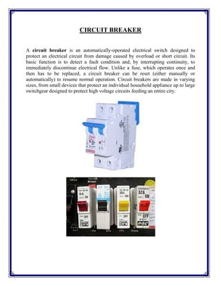
  • 1. CIRCUIT BREAKER A circuit breaker is an automatically-operated electrical switch designed to protect an electrical circuit from damage caused by overload or short circuit. Its basic function is to detect a fault condition and, by interrupting continuity, to immediately discontinue electrical flow. Unlike a fuse, which operates once and then has to be replaced, a circuit breaker can be reset (either manually or automatically) to resume normal operation. Circuit breakers are made in varying sizes, from small devices that protect an individual household appliance up to large switchgear designed to protect high voltage circuits feeding an entire city.
  • 2. Origins An early form of circuit breaker was described by Edison in an 1879 patent application, although his commercial power distribution system used fuses.[1] Its purpose was to protect lighting circuit wiring from accidental short-circuits and overloads. Operation All circuit breakers have common features in their operation, although details vary substantially depending on the voltage class, current rating and type of the circuit breaker. The circuit breaker must detect a fault condition; in low-voltage circuit breakers this is usually done within the breaker enclosure. Circuit breakers for large currents or high voltages are usually arranged with pilot devices to sense a fault current and to operate the trip opening mechanism. The trip solenoid that releases the latch is usually energized by a separate battery, although some high-voltage circuit breakers are self-contained with current transformers, protection relays, and an internal control power source. Once a fault is detected, contacts within the circuit breaker must open to interrupt the circuit; some mechanically-stored energy (using something such as springs or compressed air) contained within the breaker is used to separate the contacts, although some of the energy required may be obtained from the fault current itself. Small circuit breakers may be manually operated; larger units have solenoids to trip the mechanism, and electric motors to restore energy to the springs. The circuit breaker contacts must carry the load current without excessive heating, and must also withstand the heat of the arc produced when interrupting the circuit. Contacts are made of copper or copper alloys, silver alloys, and other materials. Service life of the contacts is limited by the erosion due to interrupting the arc. Miniature and molded case circuit breakers are usually discarded when the contacts are worn, but power circuit breakers and high-voltage circuit breakers have replaceable contacts. When a current is interrupted, an arc is generated. This arc must be contained, cooled, and extinguished in a controlled way, so that the gap between the contacts can again withstand the voltage in the circuit. Different circuit breakers use vacuum, air, insulating gas, or oil as the medium in which the arc forms.
  • 3. Different techniques are used to extinguish the arc including:  Lengthening of the arc  Intensive cooling (in jet chambers)  Division into partial arcs  Zero point quenching (Contacts open at the zero current time crossing of the AC waveform, effectively breaking no load current at the time of opening. The zero crossing occurs at twice the line frequency i.e. 100 times per second for 50Hz ac and 120 times per second for 60Hz ac )  Connecting capacitors in parallel with contacts in DC circuits Finally, once the fault condition has been cleared, the contacts must again be closed to restore power to the interrupted circuit. Working Principle Miniature Circuit Breakers are based on thermal magnetic technology. The protection is Provided by combining a temperature sensitive device (bimetal) and a current sensitive electromagnetic device. Both components trigger the mechanism mechanically. The MCB design is based on current limiting technology. Arc interruption Miniature low-voltage circuit breakers use air alone to extinguish the arc. Larger ratings will have metal plates or non-metallic arc chutes to divide and cool the arc. Magnetic blowout coils deflect the arc into the arc chute. In larger ratings, oil circuit breakers rely upon vaporization of some of the oil to blast a jet of oil through the arc. Gas (usually sulfur hexafluoride) circuit breakers sometimes stretch the arc using a magnetic field, and then rely upon the dielectric strength of the sulfur hexafluoride (SF6) to quench the stretched arc. Vacuum circuit breakers have minimal arcing (as there is nothing to ionize other than the contact material), so the arc quenches when it is stretched a very small
  • 4. amount (<2–3 mm). Vacuum circuit breakers are frequently used in modern medium-voltage switchgear to 35,000 volts. Air circuit breakers may use compressed air to blow out the arc, or alternatively, the contacts are rapidly swung into a small sealed chamber, the escaping of the displaced air thus blowing out the arc. Circuit breakers are usually able to terminate all current very quickly: typically the arc is extinguished between 30 ms and 150 ms after the mechanism has been tripped, depending upon age and construction of the device. Short circuit current Circuit breakers are rated both by the normal current that are expected to carry, and the maximum short-circuit current that they can safely interrupt. Under short-circuit conditions, a current many times greater than normal can exist (see maximum prospective short circuit current). When electrical contacts open to interrupt a large current, there is a tendency for an arc to form between the opened contacts, which would allow the current to continue. Therefore, circuit breakers must incorporate various features to divide and extinguish the arc. In air-insulated and miniature breakers an arc chute structure consisting (often) of metal plates or ceramic ridges cools the arc, and magnetic blowout coils deflect the arc into the arc chute. Larger circuit breakers such as those used in electrical power distribution may use vacuum, an inert gas such as sulphur hexafluoride or have contacts immersed in oil to suppress the arc. The maximum short-circuit current that a breaker can interrupt is determined by testing. Application of a breaker in a circuit with a prospective short-circuit current higher than the breaker's interrupting capacity rating may result in failure of the breaker to safely interrupt a fault. In a worst-case scenario the breaker may successfully interrupt the fault, only to explode when reset. Miniature circuit breakers used to protect control circuits or small appliances may not have sufficient interrupting capacity to use at a panel board; these circuit breakers are called "supplemental circuit protectors" to distinguish them from distribution-type circuit breakers.
  • 5. Standard current ratings International Standard IEC 60898-1 and European Standard EN 60898-1 define the rated current In of a circuit breaker for low voltage distribution applications as the current that the breaker is designed to carry continuously (at an ambient air temperature of 30 °C). The commonly-available preferred values for the rated current are 6 A, 10 A, 13 A, 16 A, 20 A, 25 A, 32 A, 40 A, 50 A, 63 A, 80 A and 100 A[3] (Renard series, slightly modified to include current limit of British BS 1363 sockets). The circuit breaker is labeled with the rated current in amperes, but without the unit symbol "A". Instead, the ampere figure is preceded by a letter "B", "C" or "D" that indicates the instantaneous tripping current, that is the minimum value of current that causes the circuit-breaker to trip without intentional time delay (i.e., in less than 100 ms), expressed in terms of In: Type Instantaneous tripping current B above 3 In up to and including 5 In C above 5 In up to and including 10 In D above 10 In up to and including 20 In K above 8 In up to and including 12 In For the protection of loads that cause frequent short duration (approximately 400 ms to 2 s) current peaks in normal operation. Z above 2 In up to and including 3 In for periods in the order of tens of seconds. For the protection of loads such as semiconductor devices or measuring circuits using current transformers. Types of circuit breaker
  • 6. Front panel of a 1250 A air circuit breaker manufactured by ABB. This low voltage power circuit breaker can be withdrawn from its housing for servicing. Trip characteristics are configurable via DIP switches on the front panel. Many different classifications of circuit breakers can be made, based on their features such as voltage class, construction type, interrupting type, and structural features. Low voltage circuit breakers Low voltage (less than 1000 VAC) types are common in domestic, commercial and industrial application, include:  MCB (Miniature Circuit Breaker)—rated current not more than 100 A. Trip characteristics normally not adjustable. Thermal or thermal-magnetic operation. Breakers illustrated above are in this category.  MCCB (Moulded Case Circuit Breaker)—rated current up to 1000 A. Thermal or thermal-magnetic operation. Trip current may be adjustable in larger ratings.  Low voltage power circuit breakers can be mounted in multi-tiers in LV switchboards or switchgear cabinets. The characteristics of LV circuit breakers are given by international standards such as IEC 947. These circuit breakers are often installed in draw-out enclosures that allow removal and interchange without dismantling the switchgear. Large low-voltage molded case and power circuit breakers may have electrical motor operators, allowing them to be tripped (opened) and closed under remote control. These may form part of an automatic transfer switch system for standby power. Low-voltage circuit breakers are also made for direct-current (DC) applications, for example DC supplied for subway lines. Special breakers are required for direct current because the arc does not have a natural tendency to go out on each half cycle as for alternating current. A direct current circuit breaker will have blow-out coils which generate a magnetic field that rapidly stretches the arc when interrupting direct current.
  • 7. Small circuit breakers are either installed directly in equipment, or are arranged in a breaker panel. Photo of inside of a circuit breaker The 10 ampere DIN rail-mounted thermal-magnetic miniature circuit breaker is the most common style in modern domestic consumer units and commercial electrical distribution boards throughout Europe. The design includes the following components: 1. Actuator lever - used to manually trip and reset the circuit breaker. Also indicates the status of the circuit breaker (On or Off/tripped). Most breakers are designed so they can still trip even if the lever is held or locked in the "on" position. This is sometimes referred to as "free trip" or "positive trip" operation. 2. Actuator mechanism - forces the contacts together or apart. 3. Contacts - Allow current when touching and break the current when moved apart. 4. Terminals 5. Bimetallic strip 6. Calibration screw - allows the manufacturer to precisely adjust the trip current of the device after assembly. 7. Solenoid 8. Arc divider/extinguisher
  • 8. Magnetic circuit breaker Magnetic circuit breakers use a solenoid (electromagnet) whose pulling force increases with the current. Certain designs utilize electromagnetic forces in addition to those of the solenoid. The circuit breaker contacts are held closed by a latch. As the current in the solenoid increases beyond the rating of the circuit breaker, the solenoid's pull releases the latch which then allows the contacts to open by spring action. Some types of magnetic breakers incorporate a hydraulic time delay feature using a viscous fluid. The core is restrained by a spring until the current exceeds the breaker rating. During an overload, the speed of the solenoid motion is restricted by the fluid. The delay permits brief current surges beyond normal running current for motor starting, energizing equipment, etc. Short circuit currents provide sufficient solenoid force to release the latch regardless of core position thus bypassing the delay feature. Ambient temperature affects the time delay but does not affect the current rating of a magnetic breaker. Thermal magnetic circuit breaker Thermal magnetic circuit breakers, which are the type found in most distribution boards, incorporate both techniques with the electromagnet responding instantaneously to large surges in current (short circuits) and the bimetallic strip responding to less extreme but longer-term over-current conditions. Common trip breakers Three pole common trip breaker for supplying a three-phase device. This breaker has a 2 A rating
  • 9. When supplying a branch circuit with more than one live conductor, each live conductor must be protected by a breaker pole. To ensure that all live conductors are interrupted when any pole trips, a "common trip" breaker must be used. These may either contain two or three tripping mechanisms within one case, or for small breakers, may externally tie the poles together via their operating handles. Two pole common trip breakers are common on 120/240 volt systems where 240 volt loads (including major appliances or further distribution boards) span the two live wires. Three-pole common trip breakers are typically used to supply three-phase electric power to large motors or further distribution boards. Two and four pole breakers are used when there is a need to disconnect the neutral wire, to be sure that no current can flow back through the neutral wire from other loads connected to the same network when people need to touch the wires for maintenance. Separate circuit breakers must never be used for disconnecting live and neutral, because if the neutral gets disconnected while the live conductor stays connected, a dangerous condition arises: the circuit will appear de-energized (appliances will not work), but wires will stay live and RCDs will not trip if someone touches the live wire (because RCDs need power to trip). This is why only common trip breakers must be used when switching of the neutral wire is needed. Medium-voltage circuit breakers Medium-voltage circuit breakers rated between 1 and 72 kV may be assembled into metal-enclosed switchgear line ups for indoor use, or may be individual components installed outdoors in a substation. Air-break circuit breakers replaced oil-filled units for indoor applications, but are now themselves being replaced by vacuum circuit breakers (up to about 35 kV). Like the high voltage circuit breakers described below, these are also operated by current sensing protective relays operated through current transformers. The characteristics of MV breakers are given by international standards such as IEC 62271. Medium-voltage circuit breakers nearly always use separate current sensors and protection relays, instead of relying on built-in thermal or magnetic overcurrent sensors.
  • 10. Medium-voltage circuit breakers can be classified by the medium used to extinguish the arc:  Vacuum circuit breaker—With rated current up to 3000 A, these breakers interrupt the current by creating and extinguishing the arc in a vacuum container. These are generally applied for voltages up to about 35,000 V,[4] which corresponds roughly to the medium-voltage range of power systems. Vacuum circuit breakers tend to have longer life expectancies between overhaul than do air circuit breakers.  Air circuit breaker—Rated current up to 10,000 A. Trip characteristics are often fully adjustable including configurable trip thresholds and delays. Usually electronically controlled, though some models are microprocessor controlled via an integral electronic trip unit. Often used for main power distribution in large industrial plant, where the breakers are arranged in draw-out enclosures for ease of maintenance.  SF6 circuit breakers extinguish the arc in a chamber filled with sulfur hexafluoride gas. Medium-voltage circuit breakers may be connected into the circuit by bolted connections to bus bars or wires, especially in outdoor switchyards. Medium- voltage circuit breakers in switchgear line-ups are often built with draw-out construction, allowing the breaker to be removed without disturbing the power circuit connections, using a motor-operated or hand-cranked mechanism to separate the breaker from its enclosure. High-voltage circuit breakers 400 kV SF6 live tank circuit breakers
  • 11. 115 kV bulk oil circuit breaker Electrical power transmission networks are protected and controlled by high- voltage breakers. The definition of high voltage varies but in power transmission work is usually thought to be 72.5 kV or higher, according to a recent definition by the International Electrotechnical Commission (IEC). High-voltage breakers are nearly always solenoid-operated, with current sensing protective relays operated through current transformers. In substations the protection relay scheme can be complex, protecting equipment and busses from various types of overload or ground/earth fault. High-voltage breakers are broadly classified by the medium used to extinguish the arc.  Bulk oil  Minimum oil  Air blast  Vacuum  SF6 Some of the manufacturers are ABB, GE (General Electric) , AREVA, Mitsubishi Electric, Pennsylvania Breaker, Siemens, Toshiba, Končar HVS, BHEL, CGL, Siemens and others. Due to environmental and cost concerns over insulating oil spills, most new breakers use SF6 gas to quench the arc. Circuit breakers can be classified as live tank, where the enclosure that contains the breaking mechanism is at line potential, or dead tank with the enclosure at earth
  • 12. potential. High-voltage AC circuit breakers are routinely available with ratings up to 765 kV. High-voltage circuit breakers used on transmission systems may be arranged to allow a single pole of a three-phase line to trip, instead of tripping all three poles; for some classes of faults this improves the system stability and availability. Sulfur hexafluoride (SF6) high-voltage circuit-breakers I. A sulfur hexafluoride circuit breaker uses contacts surrounded by sulfur hexafluoride gas to quench the arc. They are most often used for transmission-level voltages and may be incorporated into compact gas- insulated switchgear. In cold climates, supplemental heating or de-rating of the circuit breakers may be required due to liquefaction of the SF6 gas. APPLICATIONS B Type For protection of Resistive loads such as bulbs, heaters etc. C type For protection of Inductive loads such as motors, air conditioners etc. D type For protection of Cables and highly inductive loads which have high starting current such as transformers. FEATURES . • DC MCB incorporates built in permanent magnet, which directs the . arc in to the arc quenching chamber. . • Free from nuisance tripping caused by vibrations. . • Clear indication of polarity by the use of stickers, + sign on incoming terminal of single pole and + symbol on first pole/ -symbol on second pole of 2 pole MCBs. • Time constant > 5 ms. • DC MCB with extended terminals meeting RSDO specification no. SPEC/E-12/1/04 are also available.
  • 13. CONTENTS  Origins  Operation  Working principle  Arc interruption  Short circuit current  Standard current ratings  Types of circuit breaker o 1 Low voltage circuit breakers o 2 Magnetic circuit breaker o 3 Thermal magnetic circuit breaker o 4 Common trip breakers o 5 Medium-voltage circuit breakers o 6 High-voltage circuit breakers o 7 Sulfur hexafluoride (SF6) high-voltage circuit-breakers  Application  Features