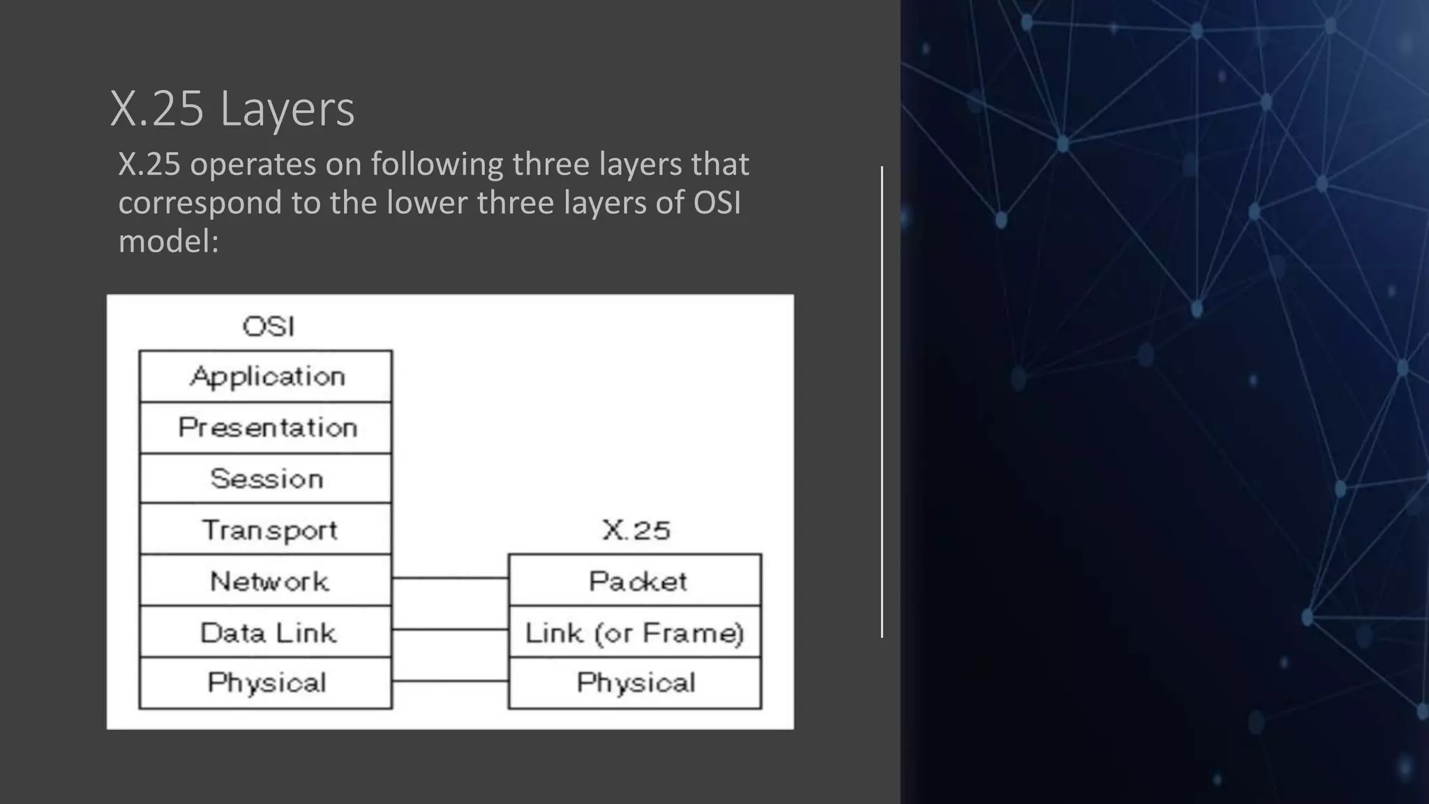
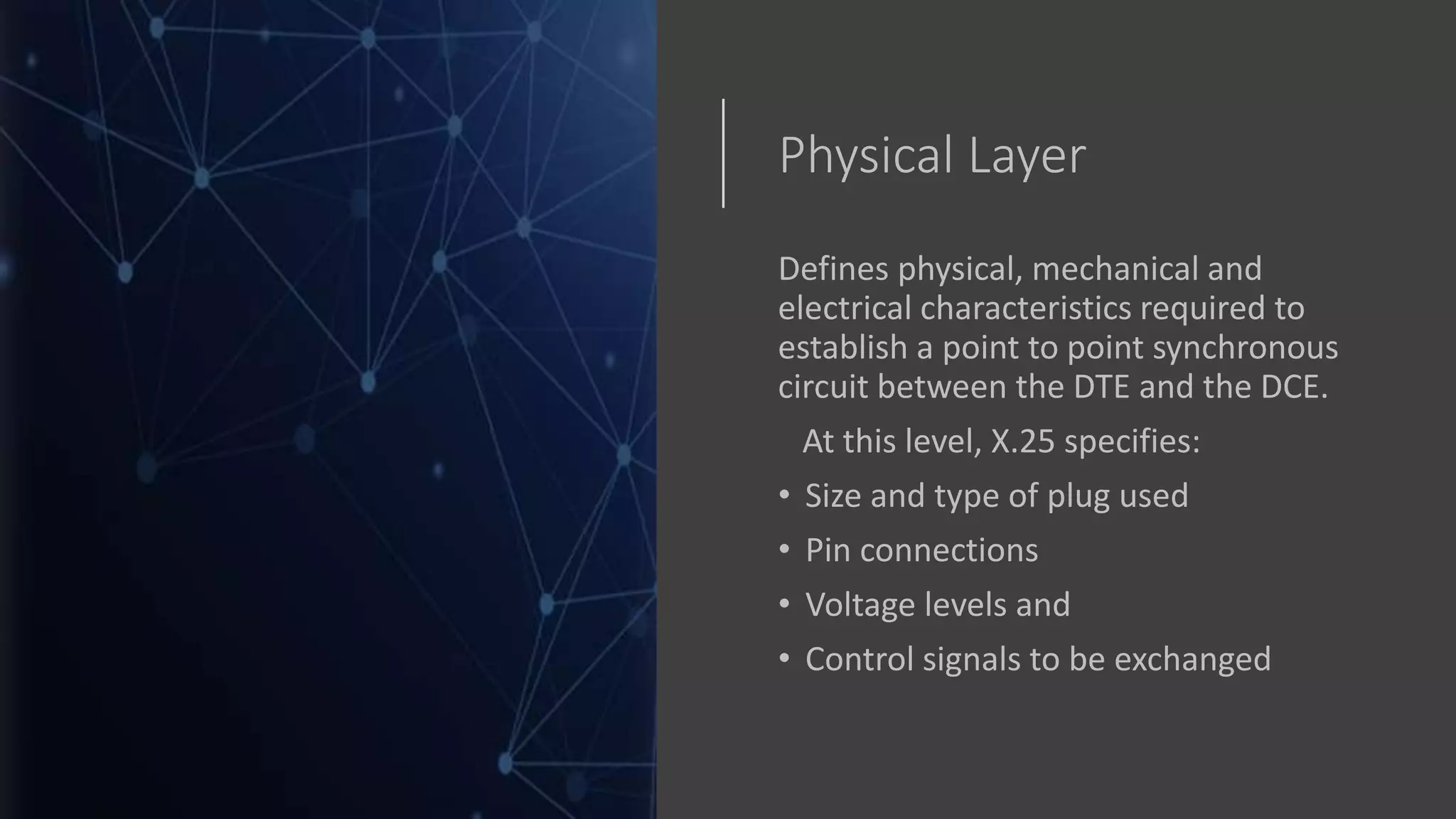
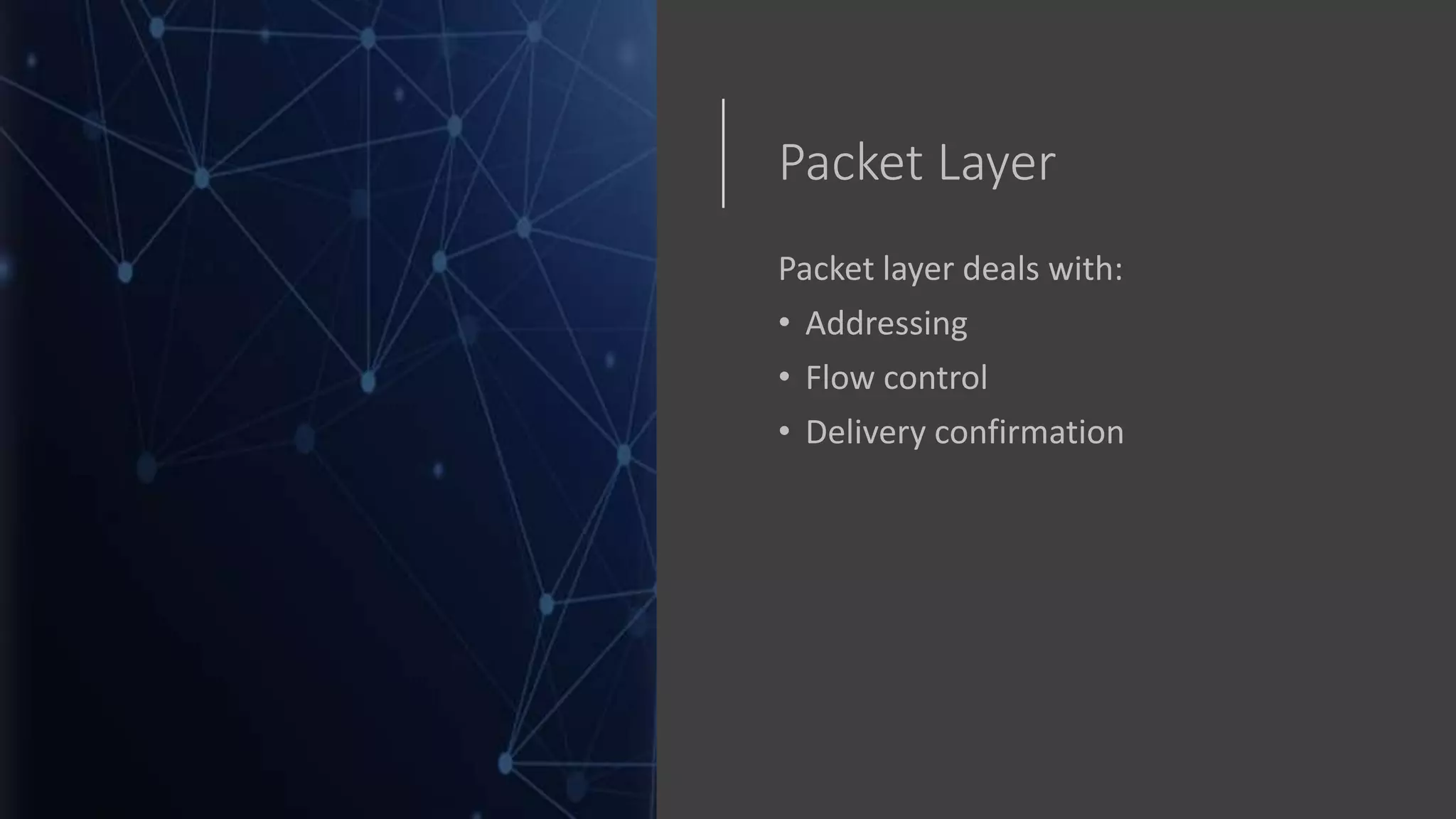
X.25
Hafsah MR
X.25
STANDARD NETWORKING
PROTOCOL FOR WIDE
AREA NETWORK (WAN)
PACKET SWITCHED
NETWORK
PUBLIC DATA NETWORK
(PDN)
SYNCHRONOUS
X.25
• Full duplex communication
• Connection oriented
• Packets are generally up to 128 bytes in size, although maximum packet sizes range from 64 to
4096 bytes, depending on the system
• X.25 networks were popular during the 1980s and were replaced by newer WAN technologies:
Frame relay, ISDN, T-carrier and Internet protocol (IP) systems
X.25
Applications
• Inventory control
• Credit checking systems/credit card
verification: ATM transactions
• Banking transactions
• Aeronautical business
• Electronic mail
• Distributed data processing
• Telecommunications companies
X.25 Devices
• X.25 devices fall into following common
categories:
• Packet-switching exchange (PSE)
• Data terminal equipment (DTE)
• Data circuit-terminating equipment (DCE)
• Packet assembler/disassembler (PAD)
X.25 Layers
X.25 operates on following three layers that
correspond to the lower three layers of OSI
model:
Physical Layer
Defines physical, mechanical and
electrical characteristics required to
establish a point to point synchronous
circuit between the DTE and the DCE.
At this level, X.25 specifies:
• Size and type of plug used
• Pin connections
• Voltage levels and
• Control signals to be exchanged
Frame Layer
Packages users’ information into frames
to achieve:
• Efficient data transfer
• Synchronization between the sender
and receiver
• Detection and recovery of
transmission errors
Packet Layer
Packet layer deals with:
• Addressing
• Flow control
• Delivery confirmation
Working
• To exchange information, the packet
level sends a call request packet
through the networks DCE to the
intended destination
• If the incoming call is accepted, a
circuit is established: switched
virtual circuit
X.25 Drawbacks
X.25 has several drawbacks:
• X.25 has a low 64-kbps data rate. By the 1990s,
there was a need for higher- data-rate WANs.
• X.25 has extensive flow and error control at both
the data link layer and the network layer. This was so
because X.25 was designed in the 1970s, when the
available transmission media were more prone to
errors. Flow and error control at both layers create a
large overhead and slow down transmissions. X.25
requires acknowledgments for both data link layer
frames and network layer packets that are sent
between nodes and between source and destination.

X.25 - Network Protocol

  • 1.
  • 2.
    X.25 STANDARD NETWORKING PROTOCOL FORWIDE AREA NETWORK (WAN) PACKET SWITCHED NETWORK PUBLIC DATA NETWORK (PDN) SYNCHRONOUS
  • 3.
    X.25 • Full duplexcommunication • Connection oriented • Packets are generally up to 128 bytes in size, although maximum packet sizes range from 64 to 4096 bytes, depending on the system • X.25 networks were popular during the 1980s and were replaced by newer WAN technologies: Frame relay, ISDN, T-carrier and Internet protocol (IP) systems
  • 4.
    X.25 Applications • Inventory control •Credit checking systems/credit card verification: ATM transactions • Banking transactions • Aeronautical business • Electronic mail • Distributed data processing • Telecommunications companies
  • 5.
    X.25 Devices • X.25devices fall into following common categories: • Packet-switching exchange (PSE) • Data terminal equipment (DTE) • Data circuit-terminating equipment (DCE) • Packet assembler/disassembler (PAD)
  • 6.
    X.25 Layers X.25 operateson following three layers that correspond to the lower three layers of OSI model:
  • 7.
    Physical Layer Defines physical,mechanical and electrical characteristics required to establish a point to point synchronous circuit between the DTE and the DCE. At this level, X.25 specifies: • Size and type of plug used • Pin connections • Voltage levels and • Control signals to be exchanged
  • 8.
    Frame Layer Packages users’information into frames to achieve: • Efficient data transfer • Synchronization between the sender and receiver • Detection and recovery of transmission errors
  • 9.
    Packet Layer Packet layerdeals with: • Addressing • Flow control • Delivery confirmation
  • 10.
    Working • To exchangeinformation, the packet level sends a call request packet through the networks DCE to the intended destination • If the incoming call is accepted, a circuit is established: switched virtual circuit
  • 11.
    X.25 Drawbacks X.25 hasseveral drawbacks: • X.25 has a low 64-kbps data rate. By the 1990s, there was a need for higher- data-rate WANs. • X.25 has extensive flow and error control at both the data link layer and the network layer. This was so because X.25 was designed in the 1970s, when the available transmission media were more prone to errors. Flow and error control at both layers create a large overhead and slow down transmissions. X.25 requires acknowledgments for both data link layer frames and network layer packets that are sent between nodes and between source and destination.