Download to read offline
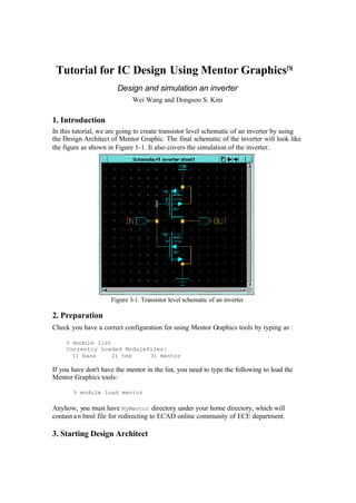
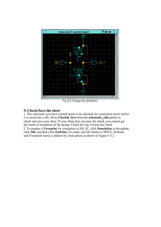
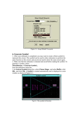


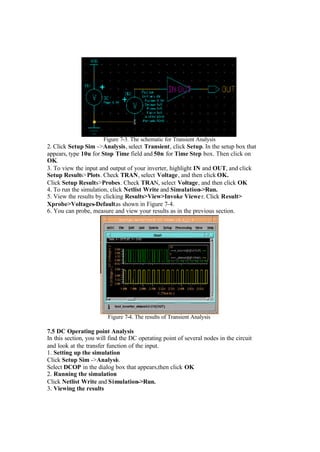


This tutorial provides instructions for using Mentor Graphics Design Architect to design and simulate a transistor-level inverter schematic. The steps include: 1) preparing the Mentor Graphics tools, 2) starting Design Architect and creating a new schematic, 3) adding transistor components from the library and connecting them to form the inverter, 4) simulating the inverter through DC, transient, and DC operating point analyses to observe the input-output voltage behavior.


