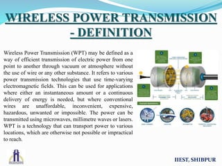
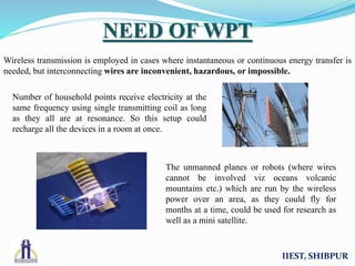
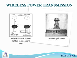
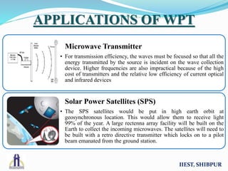
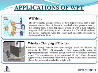
Wireless Power
Transmission
Group 1
Group Members
Akash Banerjee 510614005
Poushali Ray 510614064
Rumani Chakraborty 510614011
Saikat Dey 510614034
Samrat Chatterjee 510614016
Sayan Sen 510614046
Semester Third
Session 2015-2016
IIEST, SHIBPUR
Wireless Power Transmission (WPT) may be defined as a
way of efficient transmission of electric power from one
point to another through vacuum or atmosphere without
the use of wire or any other substance. It refers to various
power transmission technologies that use time-varying
electromagnetic fields. This can be used for applications
where either an instantaneous amount or a continuous
delivery of energy is needed, but where conventional
wires are unaffordable, inconvenient, expensive,
hazardous, unwanted or impossible. The power can be
transmitted using microwaves, millimetre waves or lasers.
WPT is a technology that can transport power to various
locations, which are otherwise not possible or impractical
to reach.
IIEST, SHIBPUR
WIRELESS POWER TRANSMISSION
- DEFINITION
Wireless transmission is employed in cases where instantaneous or continuous energy transfer is
needed, but interconnecting wires are inconvenient, hazardous, or impossible.
IIEST, SHIBPUR
NEED OF WPT
Number of household points receive electricity at the
same frequency using single transmitting coil as long
as they all are at resonance. So this setup could
recharge all the devices in a room at once.
The unmanned planes or robots (where wires
cannot be involved viz oceans volcanic
mountains etc.) which are run by the wireless
power over an area, as they could fly for
months at a time, could be used for research as
well as a mini satellite.
In 1864, James C. Maxwell
predicted the existence of
radio waves by means of
mathematical model.
In 1884, John H. Poynting
realized that the Poynting
Vector would play an
important role in quantifying
the electromagnetic energy.
In 1888, bolstered by
Maxwell's theory, Heinrich
Hertz first succeeded in
showing experimental
evidence of radio waves by his
spark-gap radio transmitter.
Tesla successfully lighted a
small incandescent lamp by a
resonant circuit, with the
lower end connected to the
ground and the upper end free.
Wardenclyffe tower was
designed by Tesla for trans-
Atlantic wireless telephony
and also for demonstrating
wireless electrical power
transmission.
In the early 1960s, Brown
invented the rectenna which
directly converts microwaves
to DC current. He
demonstrated its ability in
1964 by powering a helicopter
from the solely through
microwaves.
IIEST, SHIBPUR
HISTORY OF WPT
Resonant circuit used to
light an incandescent
lamp
Wardenclyffe Tower
IIEST, SHIBPUR
METHODS OF WPT
• Transfer of electrical power without any physical contact in between
• Simplest example of how mutual induction works is the transformerInduction
• Electromagnetic waves used to transfer power without wires
• Power beamed to a single target by converting electricity into light, then firing this beam at a receiving target
Electromagnetic
Transmission
• Power transfer using non-radiative electromagnetic energy resonant tunnelling
• Waves would not disrupt electronic devices or cause physical injury like microwave or radio transmission.
Evanescent
Wave Coupling
• Transmitter and receiver inductors tuned to a mutual frequency; drive current modified from a sinusoidal to a non-sinusoidal
transient waveform.
• Significant power may be transmitted over a distance of up to a few times the size of the transmitter.
Electrodynamic
Induction
• Power transmission via radio waves can be made more directional, allowing longer distance power beaming, with shorter
wavelengths of electromagnetic radiation
• Rectenna may be used to convert the microwave energy back into electricity; conversion efficiencies exceeding 95% have
been realized
Radio &
Microwave
• Also known as "capacitive coupling“
• Involves electric field gradient or differential capacitance between two elevated electrodes over a conducting ground plane
for wireless energy transmission
Electrostatic
Induction
IIEST, SHIBPUR
Components :
• Rectifier circuit
• Oscillator
• Master coil
• Slave coil
• CW generator
IIEST, SHIBPUR
FULL CIRCUIT DIAGRAM
WHY 7805 IC ?
The 78xx is a family of self-contained fixed linear voltage regulator integrated circuits.
Here 7805 depicts the IC of this family where 05 is the output from the IC.
IIEST, SHIBPUR
RECTIFIER CIRCUIT
Voltage waveform after passing through
rectifier circuit.
IIEST, SHIBPUR
OSCILLATOR
 Circuit Diagram:
TYPE : COLPITT OSCILLATOR
An oscillator is required to convert a DC to a high frequency AC. Colpitt oscillator uses
inductor and capacitor for its oscillation. The distinguishing feature of this oscillator is
that the feedback for the active device is taken from a voltage divider made of two
capacitors in series across the inductor.
CALCULATION :
Frequency, f = 80k, Capacitance, C = 150nF
f=1/(2∏√(L * C/2) ) => L= (1/ (f* 2∏) )^2 / (C/2)
L = (1/ (80k * 2 * pi) )^2 / (150nF/2)
L = 52.77uH
OSCILLATOR
IIEST, SHIBPUR
AIR CORE INDUCTOR
CALCULATOR
IIEST, SHIBPUR
Master CoilSlave Coil
The two coils are of the following
dimensions.
Master coil :
Diameter : 7.5 cm
Turns : 26
Slave coil :
Diameter : 4.5cm
Turns : 200
IIEST, SHIBPUR
MASTER COIL AND SLAVE COIL
VOLTAGE WAVEFORMS IN
MASTER AND SLAVE COIL
Voltage in the master coil Voltage in the slave coil
IIEST, SHIBPUR
Circuit:
Also known as the Cockfort-Walton generator or multiplier, it converts a low AC voltage to a high DC
voltage. Unlike transformer, this eliminates the requirement for heavy core. The advantage of such circuits is
that the voltage across each stage of the cascade is equal to only twice the peak input voltage in a half wave
rectifier.
Here, it has been used to get an output DC voltage to light up an LED.
IIEST, SHIBPUR
CW GENERATOR
The circuit works on the principle of mutual inductance. Power is transferred from the
transmitter to the receiver wirelessly based on the principle of “inductive coupling”.
 When the input circuit is switched on, then first it enters the rectifier circuit where
the 6V AC is converted to 5V DC, which is then fed to the oscillator circuit.
 The signal frequency is made to 86.2kHz and is fed to the master coil.
 The slave coil, which is at some distance away, gets an induced voltage across it.
 This voltage is fed to the CW generator circuit, which then makes the output to DC
and this is then transferred to the LED.
IIEST, SHIBPUR
WORKING
IIEST, SHIBPUR
APPLICATIONS OF WPT
Microwave Transmitter
• For transmission efficiency, the waves must be focused so that all the
energy transmitted by the source is incident on the wave collection
device. Higher frequencies are also impractical because of the high
cost of transmitters and the relative low efficiency of current optical
and infrared devices
Solar Power Satellites (SPS)
• The SPS satellites would be put in high earth orbit at
geosynchronous location. This would allow them to receive light
99% of the year. A large rectenna array facility will be built on the
Earth to collect the incoming microwaves. The satellites will need to
be built with a retro directive transmitter which locks on to a pilot
beam emanated from the ground station.
IIEST, SHIBPUR
APPLICATIONS OF WPT
WiTricity
• The investigated design consists of two copper coils, each a self-
resonant system. One of the coils, attached to the power source, is
the sending unit. It fills the space around it with a non-radiative
magnetic field oscillating at MHz frequencies. This field mediates
the power exchange with the other coil specially designed to
resonate with the field.
Wireless Charging of Devices
• Wireless energy transfer has been thought about for decades by
scientists. In 2007, US researchers have successfully tested an
experimental system to deliver power to devices without the need for
wires. The experimental setup consisted of two 60cm diameter
copper coils, a transmitter attached to a power source and a receiver
placed 2m away and attached to a light bulb.
IIEST, SHIBPUR
MERITS & DEMERITS OF WPT
Merits of WPT
• The system would reduce the cost of electrical energy used by the consumer and rid the
landscape of wires, cables, and transmission towers. The electrical energy can be
economically transmitted without wires to any terrestrial distance, so there will be no
transmission and distribution loss.
Demerits of WPT
• Calculating the circulating reactive power, it was found that the frequency is very small
and such a frequency is very biologically compatible.
Thank You

Wireless Power Transmission

  • 1.
  • 2.
    Group 1 Group Members AkashBanerjee 510614005 Poushali Ray 510614064 Rumani Chakraborty 510614011 Saikat Dey 510614034 Samrat Chatterjee 510614016 Sayan Sen 510614046 Semester Third Session 2015-2016 IIEST, SHIBPUR
  • 3.
    Wireless Power Transmission(WPT) may be defined as a way of efficient transmission of electric power from one point to another through vacuum or atmosphere without the use of wire or any other substance. It refers to various power transmission technologies that use time-varying electromagnetic fields. This can be used for applications where either an instantaneous amount or a continuous delivery of energy is needed, but where conventional wires are unaffordable, inconvenient, expensive, hazardous, unwanted or impossible. The power can be transmitted using microwaves, millimetre waves or lasers. WPT is a technology that can transport power to various locations, which are otherwise not possible or impractical to reach. IIEST, SHIBPUR WIRELESS POWER TRANSMISSION - DEFINITION
  • 4.
    Wireless transmission isemployed in cases where instantaneous or continuous energy transfer is needed, but interconnecting wires are inconvenient, hazardous, or impossible. IIEST, SHIBPUR NEED OF WPT Number of household points receive electricity at the same frequency using single transmitting coil as long as they all are at resonance. So this setup could recharge all the devices in a room at once. The unmanned planes or robots (where wires cannot be involved viz oceans volcanic mountains etc.) which are run by the wireless power over an area, as they could fly for months at a time, could be used for research as well as a mini satellite.
  • 5.
    In 1864, JamesC. Maxwell predicted the existence of radio waves by means of mathematical model. In 1884, John H. Poynting realized that the Poynting Vector would play an important role in quantifying the electromagnetic energy. In 1888, bolstered by Maxwell's theory, Heinrich Hertz first succeeded in showing experimental evidence of radio waves by his spark-gap radio transmitter. Tesla successfully lighted a small incandescent lamp by a resonant circuit, with the lower end connected to the ground and the upper end free. Wardenclyffe tower was designed by Tesla for trans- Atlantic wireless telephony and also for demonstrating wireless electrical power transmission. In the early 1960s, Brown invented the rectenna which directly converts microwaves to DC current. He demonstrated its ability in 1964 by powering a helicopter from the solely through microwaves. IIEST, SHIBPUR HISTORY OF WPT
  • 6.
    Resonant circuit usedto light an incandescent lamp Wardenclyffe Tower IIEST, SHIBPUR
  • 7.
    METHODS OF WPT •Transfer of electrical power without any physical contact in between • Simplest example of how mutual induction works is the transformerInduction • Electromagnetic waves used to transfer power without wires • Power beamed to a single target by converting electricity into light, then firing this beam at a receiving target Electromagnetic Transmission • Power transfer using non-radiative electromagnetic energy resonant tunnelling • Waves would not disrupt electronic devices or cause physical injury like microwave or radio transmission. Evanescent Wave Coupling • Transmitter and receiver inductors tuned to a mutual frequency; drive current modified from a sinusoidal to a non-sinusoidal transient waveform. • Significant power may be transmitted over a distance of up to a few times the size of the transmitter. Electrodynamic Induction • Power transmission via radio waves can be made more directional, allowing longer distance power beaming, with shorter wavelengths of electromagnetic radiation • Rectenna may be used to convert the microwave energy back into electricity; conversion efficiencies exceeding 95% have been realized Radio & Microwave • Also known as "capacitive coupling“ • Involves electric field gradient or differential capacitance between two elevated electrodes over a conducting ground plane for wireless energy transmission Electrostatic Induction IIEST, SHIBPUR
  • 8.
    Components : • Rectifiercircuit • Oscillator • Master coil • Slave coil • CW generator IIEST, SHIBPUR FULL CIRCUIT DIAGRAM
  • 9.
    WHY 7805 IC? The 78xx is a family of self-contained fixed linear voltage regulator integrated circuits. Here 7805 depicts the IC of this family where 05 is the output from the IC. IIEST, SHIBPUR RECTIFIER CIRCUIT Voltage waveform after passing through rectifier circuit.
  • 10.
  • 11.
    TYPE : COLPITTOSCILLATOR An oscillator is required to convert a DC to a high frequency AC. Colpitt oscillator uses inductor and capacitor for its oscillation. The distinguishing feature of this oscillator is that the feedback for the active device is taken from a voltage divider made of two capacitors in series across the inductor. CALCULATION : Frequency, f = 80k, Capacitance, C = 150nF f=1/(2∏√(L * C/2) ) => L= (1/ (f* 2∏) )^2 / (C/2) L = (1/ (80k * 2 * pi) )^2 / (150nF/2) L = 52.77uH OSCILLATOR IIEST, SHIBPUR
  • 12.
  • 13.
    Master CoilSlave Coil Thetwo coils are of the following dimensions. Master coil : Diameter : 7.5 cm Turns : 26 Slave coil : Diameter : 4.5cm Turns : 200 IIEST, SHIBPUR MASTER COIL AND SLAVE COIL
  • 14.
    VOLTAGE WAVEFORMS IN MASTERAND SLAVE COIL Voltage in the master coil Voltage in the slave coil IIEST, SHIBPUR
  • 15.
    Circuit: Also known asthe Cockfort-Walton generator or multiplier, it converts a low AC voltage to a high DC voltage. Unlike transformer, this eliminates the requirement for heavy core. The advantage of such circuits is that the voltage across each stage of the cascade is equal to only twice the peak input voltage in a half wave rectifier. Here, it has been used to get an output DC voltage to light up an LED. IIEST, SHIBPUR CW GENERATOR
  • 16.
    The circuit workson the principle of mutual inductance. Power is transferred from the transmitter to the receiver wirelessly based on the principle of “inductive coupling”.  When the input circuit is switched on, then first it enters the rectifier circuit where the 6V AC is converted to 5V DC, which is then fed to the oscillator circuit.  The signal frequency is made to 86.2kHz and is fed to the master coil.  The slave coil, which is at some distance away, gets an induced voltage across it.  This voltage is fed to the CW generator circuit, which then makes the output to DC and this is then transferred to the LED. IIEST, SHIBPUR WORKING
  • 17.
    IIEST, SHIBPUR APPLICATIONS OFWPT Microwave Transmitter • For transmission efficiency, the waves must be focused so that all the energy transmitted by the source is incident on the wave collection device. Higher frequencies are also impractical because of the high cost of transmitters and the relative low efficiency of current optical and infrared devices Solar Power Satellites (SPS) • The SPS satellites would be put in high earth orbit at geosynchronous location. This would allow them to receive light 99% of the year. A large rectenna array facility will be built on the Earth to collect the incoming microwaves. The satellites will need to be built with a retro directive transmitter which locks on to a pilot beam emanated from the ground station.
  • 18.
    IIEST, SHIBPUR APPLICATIONS OFWPT WiTricity • The investigated design consists of two copper coils, each a self- resonant system. One of the coils, attached to the power source, is the sending unit. It fills the space around it with a non-radiative magnetic field oscillating at MHz frequencies. This field mediates the power exchange with the other coil specially designed to resonate with the field. Wireless Charging of Devices • Wireless energy transfer has been thought about for decades by scientists. In 2007, US researchers have successfully tested an experimental system to deliver power to devices without the need for wires. The experimental setup consisted of two 60cm diameter copper coils, a transmitter attached to a power source and a receiver placed 2m away and attached to a light bulb.
  • 19.
    IIEST, SHIBPUR MERITS &DEMERITS OF WPT Merits of WPT • The system would reduce the cost of electrical energy used by the consumer and rid the landscape of wires, cables, and transmission towers. The electrical energy can be economically transmitted without wires to any terrestrial distance, so there will be no transmission and distribution loss. Demerits of WPT • Calculating the circulating reactive power, it was found that the frequency is very small and such a frequency is very biologically compatible.
  • 20.