Download as PDF, PPTX
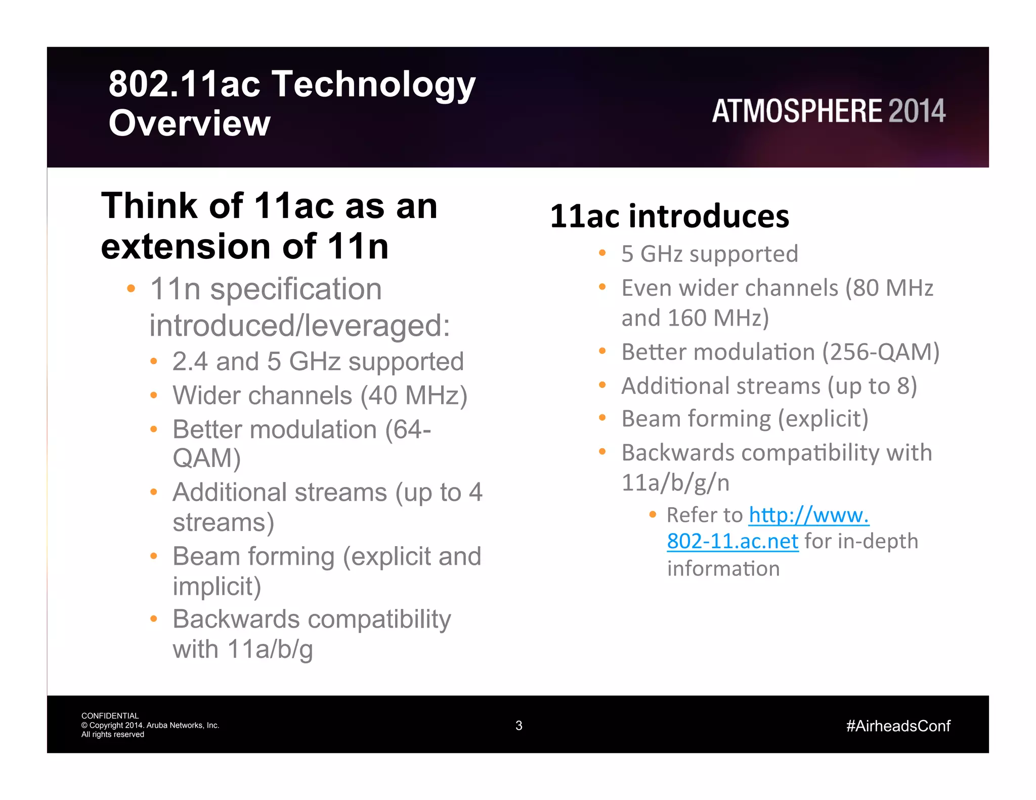
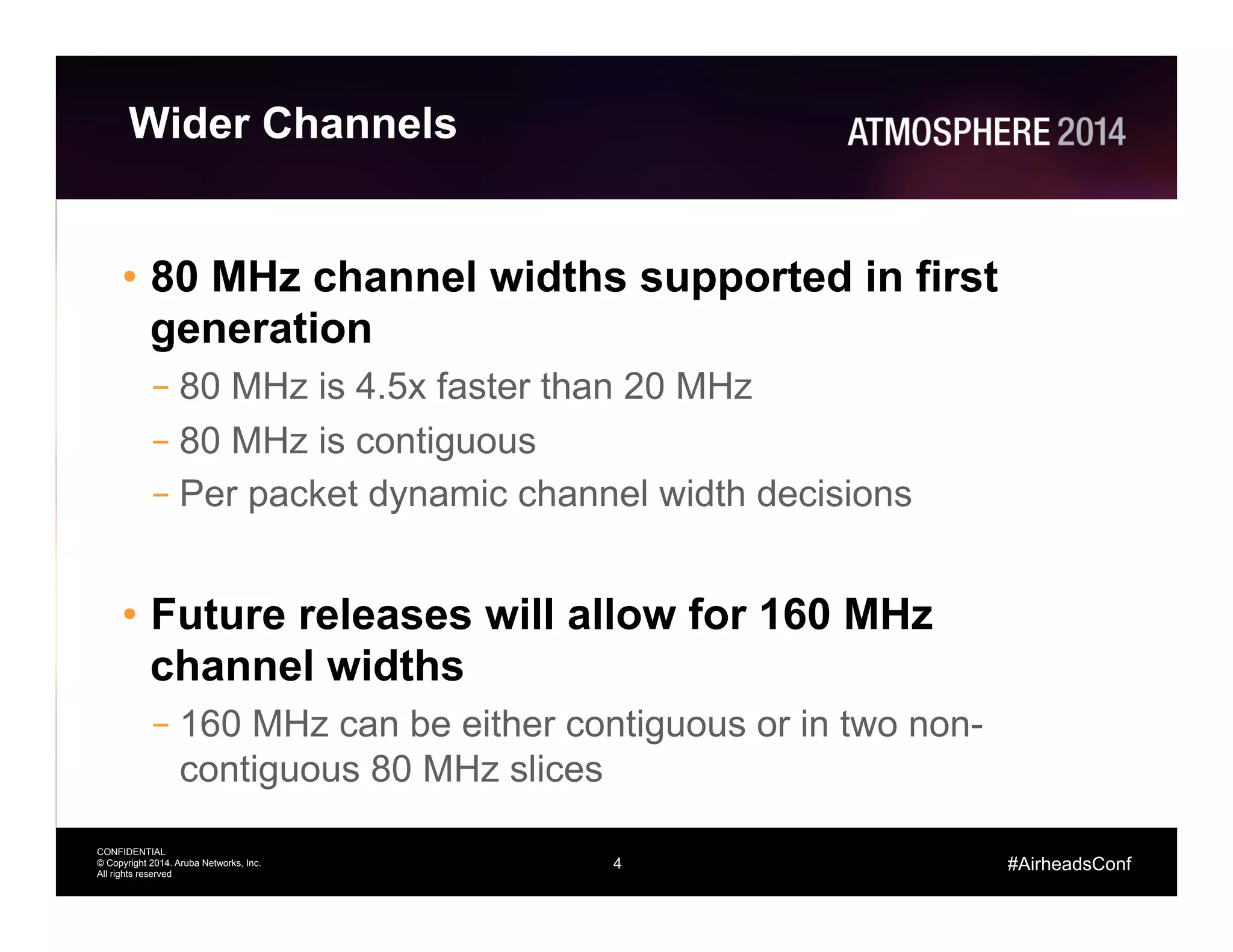
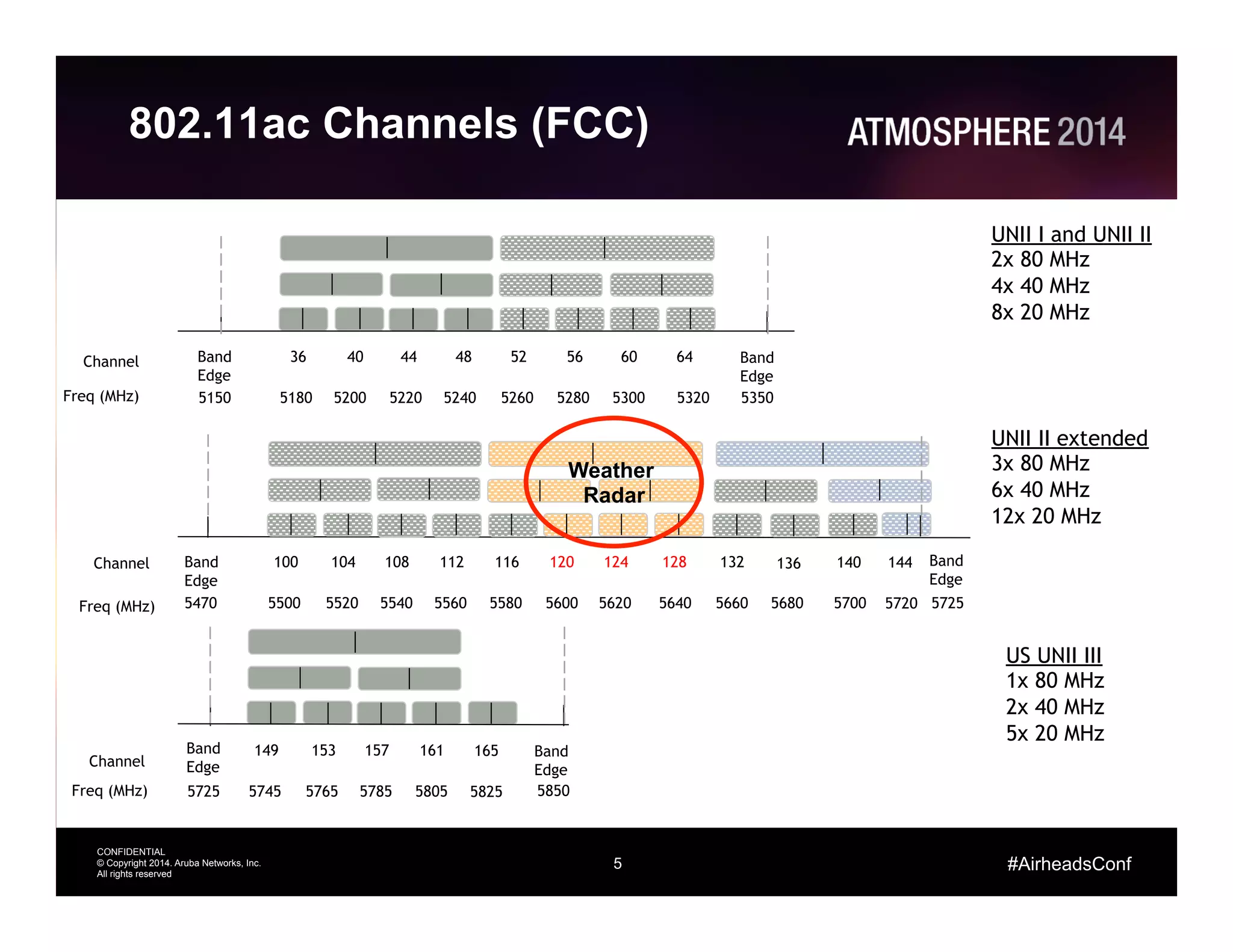
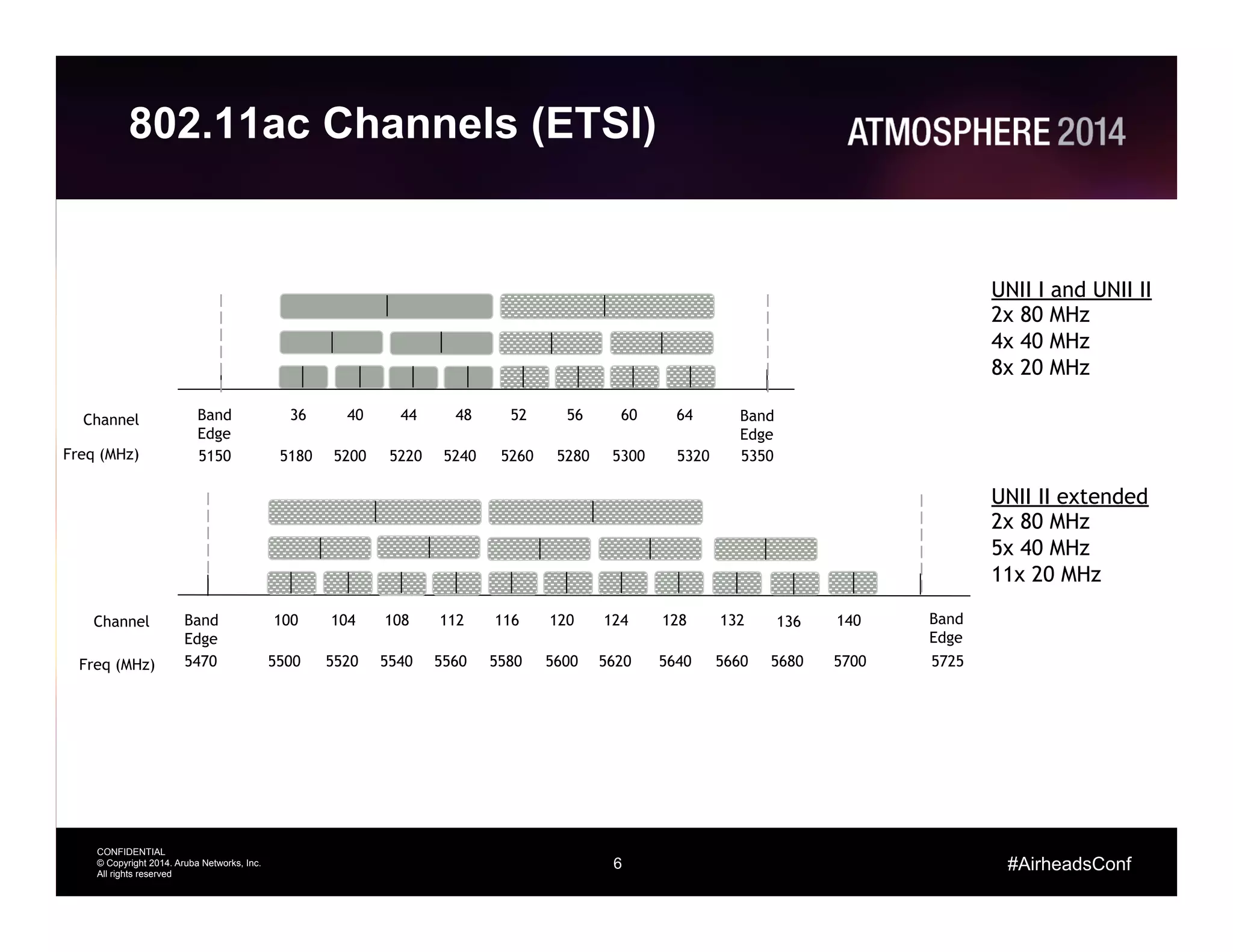

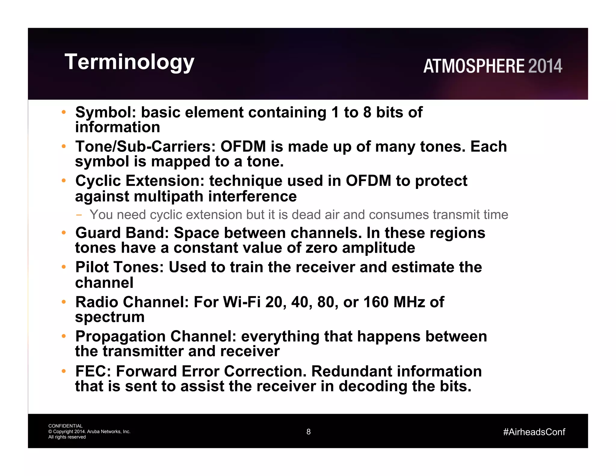
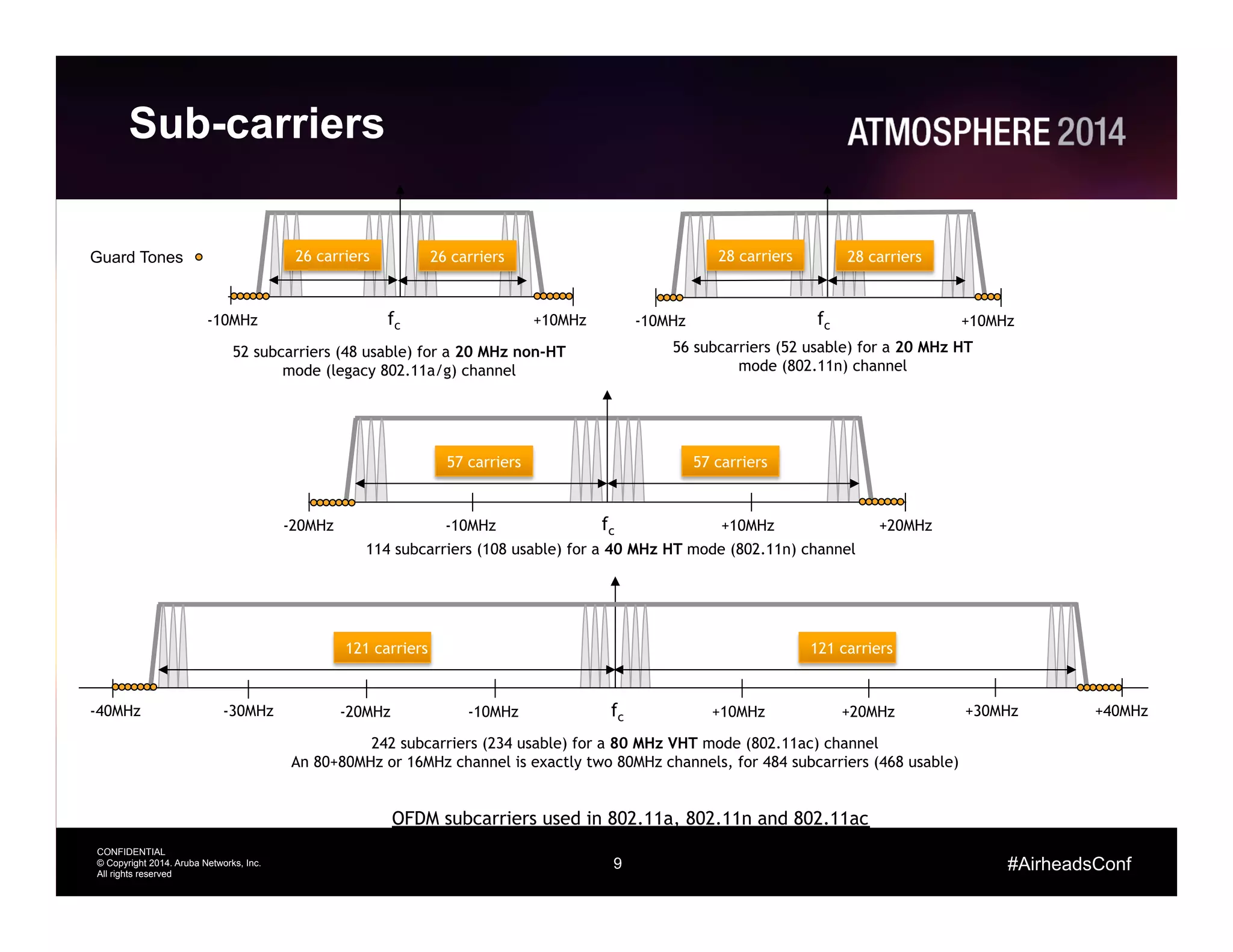
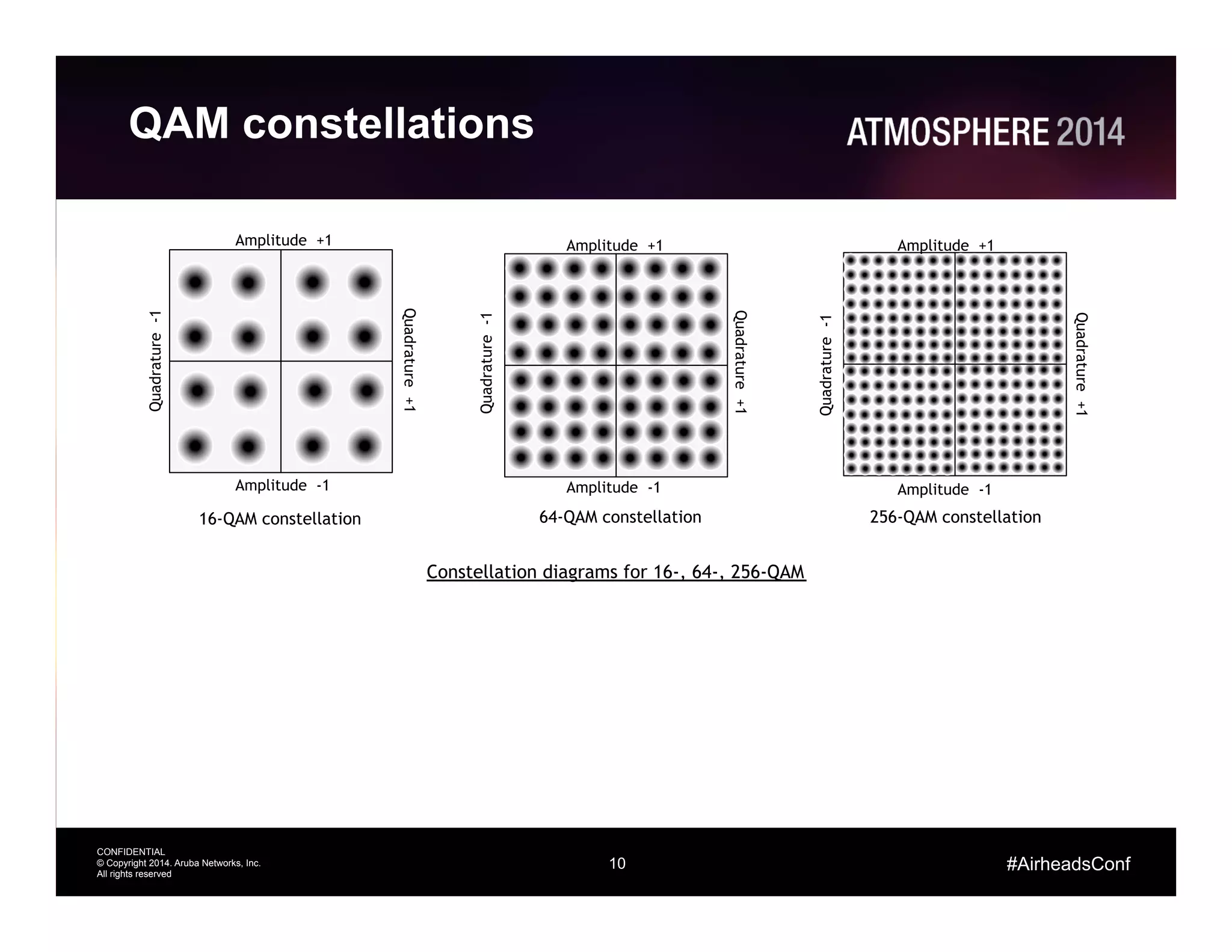
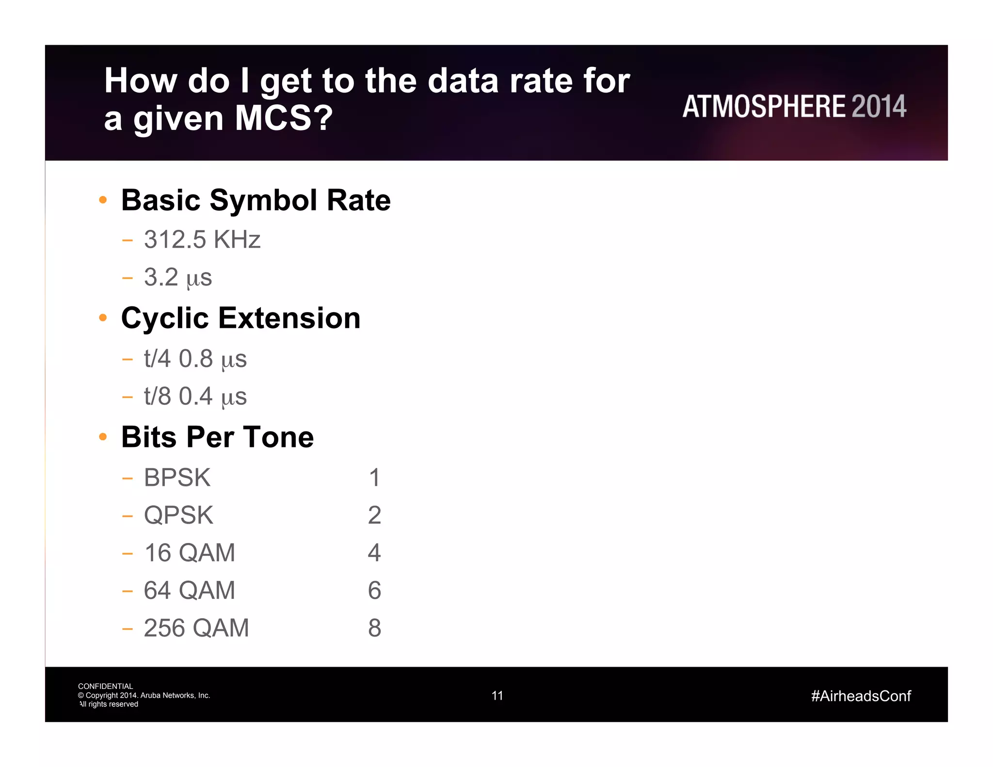
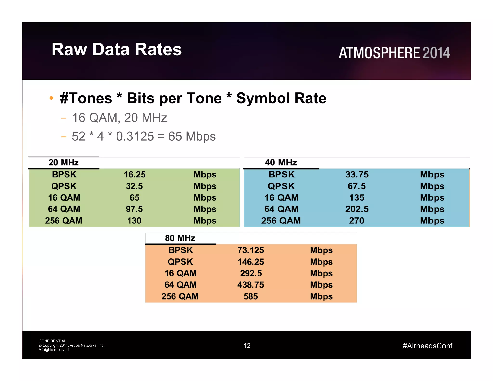
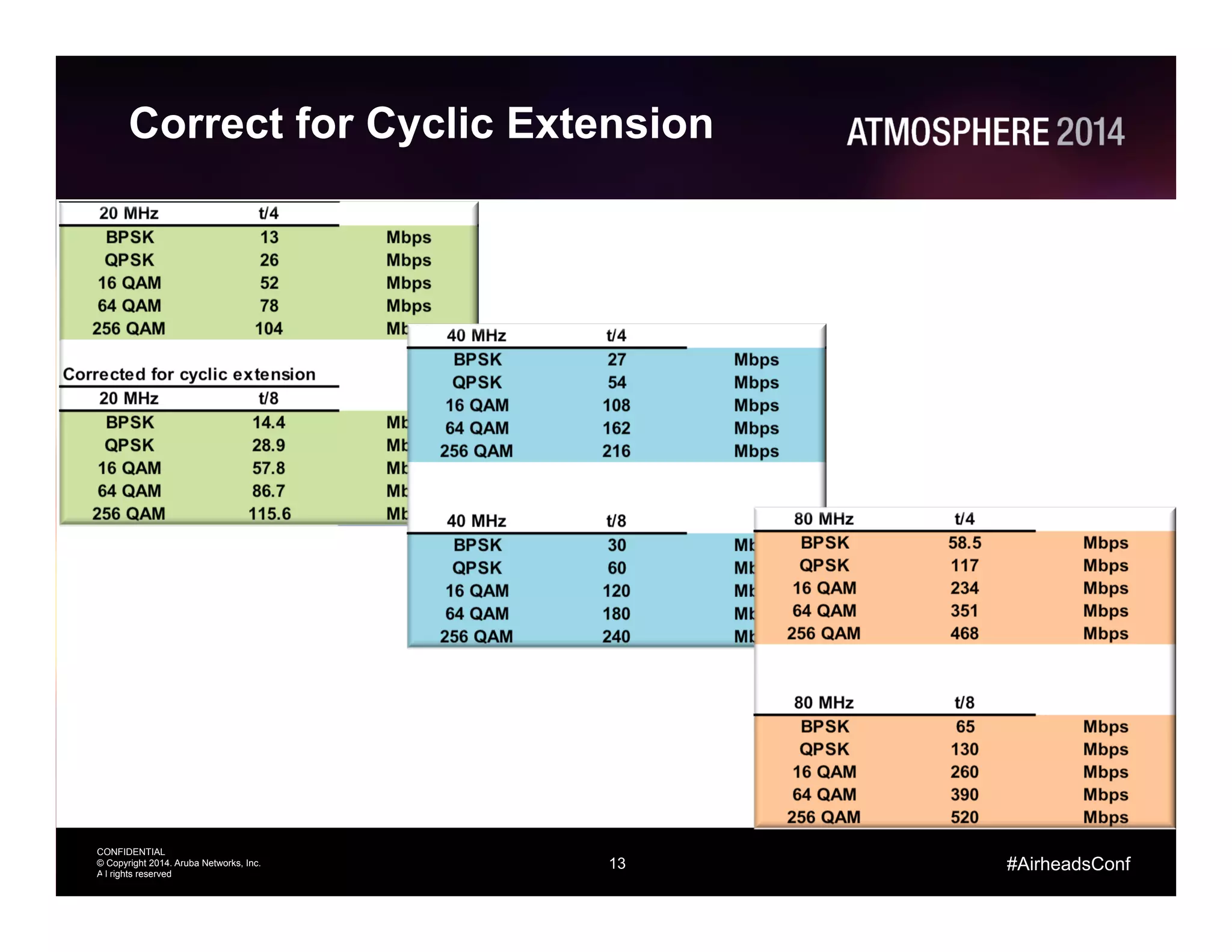

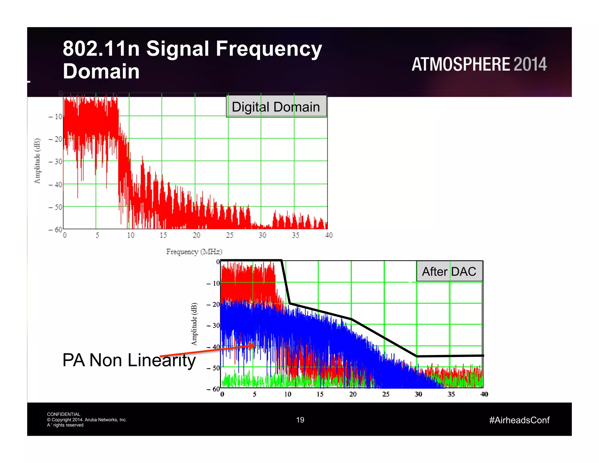
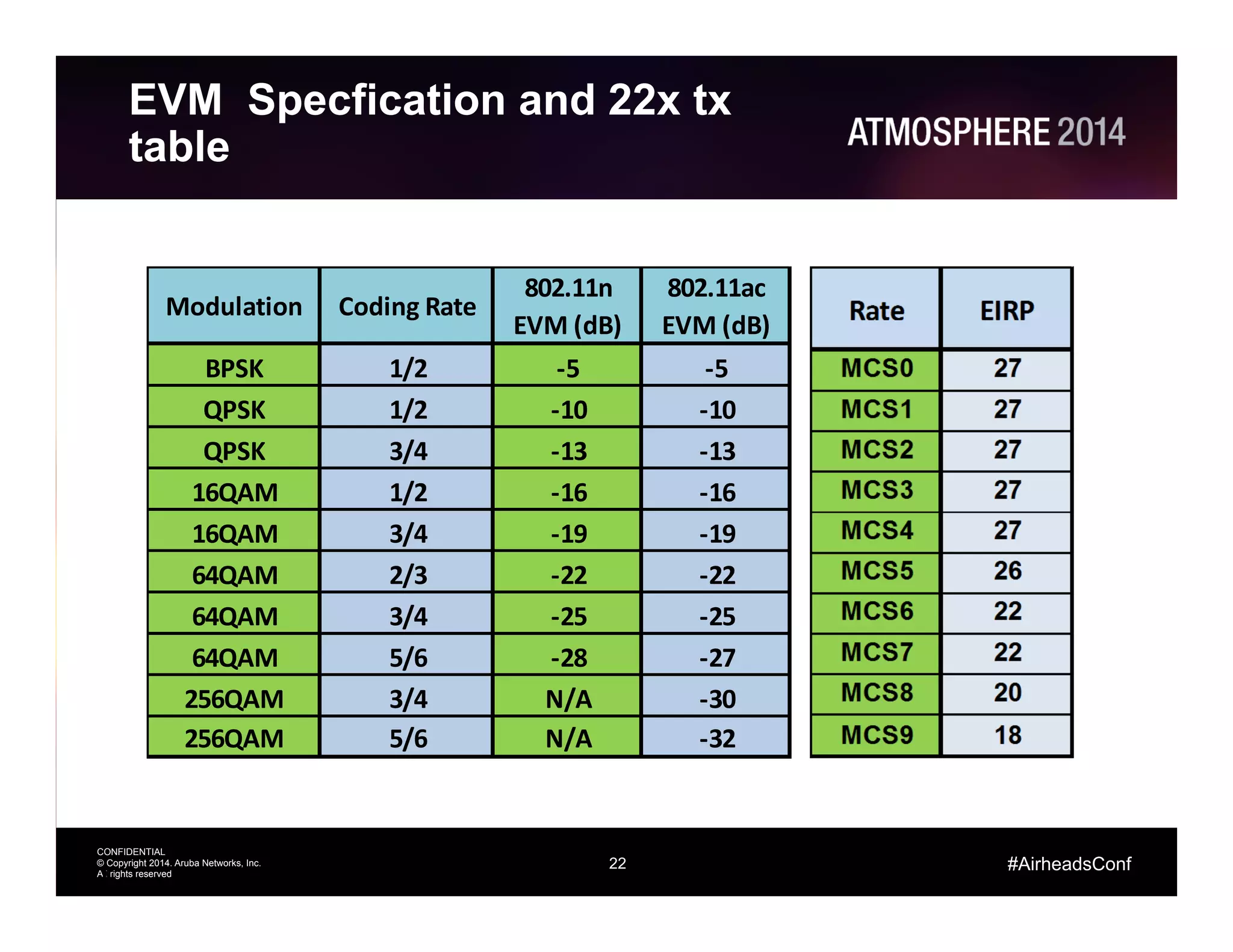


The document provides an overview of 802.11ac Wi-Fi technology, highlighting its advancements over the previous 802.11n standard, including wider channels, improved data rates, and explicit beamforming. It discusses technical aspects such as modulation types, channel frequencies, and the requirements for supporting the new standard, along with pros and cons of its implementation. The presentation also addresses the impact of infrastructure and equipment upgrades necessary for optimal utilization of 802.11ac features.


