Downloaded 198 times


![43
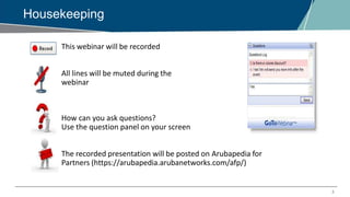
Configuration:
Creating a new cluster group profile (should be done on the MM)
(MM) [cluster2] (config) #lc-cluster group-profile vmc2
(MM) ^[cluster2] (Classic Controller Cluster Profile "vmc2") #controller 10.29.161.98
(MM) ^[cluster2] (Classic Controller Cluster Profile "vmc2") #controller 10.29.161.251
Registering to a cluster group (should be done on the MM with the
managed node as its path)
(MM) ^[cluster2] (config) #cd /md/cluster2/00:0c:29:bc:2a:96
(MM) ^[00:0c:29:bc:2a:96] (config) #lc-cluster group-membership vmc2](https://image.slidesharecdn.com/emeaairheadsarubaosclustermanager-170531055427/85/EMEA-Airheads-ArubaOS-Cluster-Manager-43-320.jpg)


![57
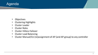
Configuration
• Load balancing is enabled by default when cluster is configured.
− Aruba7210) #show lc-cluster group-profile testlb
Redundancy:No
L2-Connected:No
Active Client Rebalance Threshold:50%
Standby Client Rebalance Threshold:75%
Unbalance Threshold:5%
• The threshold parameters can be configured in cluster group profile
from MM
(ArubaSC) [md] (config) #lc-cluster group-profile Clusterlb
(ArubaSC) ^[md] (Classic Controller Cluster Profile "Clusterlb") #active-client-rebalance-threshold
60
(ArubaSC) ^[md] (Classic Controller Cluster Profile "Clusterlb") #standby-client-rebalance-threshold
70
(ArubaSC) ^[md] (Classic Controller Cluster Profile "Clusterlb") #unbalance-threshold 10](https://image.slidesharecdn.com/emeaairheadsarubaosclustermanager-170531055427/85/EMEA-Airheads-ArubaOS-Cluster-Manager-57-320.jpg)


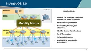
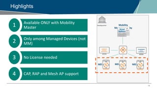
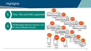
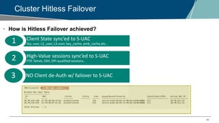
The webinar on Cluster Manager discusses key features of Aruba's clustering capabilities, including seamless campus roaming, hitless client failover, and load balancing among controllers. It covers updates in ArubaOS 8.0, detailing the functionalities of Mobility Master and the clustering architecture for improved network management. The session also addresses practical configuration settings and considerations for maintaining high availability in mission-critical networks.


![Acmp study guide_d[1]](https://cdn.slidesharecdn.com/ss_thumbnails/acmpstudyguided1-130813141231-phpapp01-thumbnail.jpg?width=640&height=640&fit=bounds)


