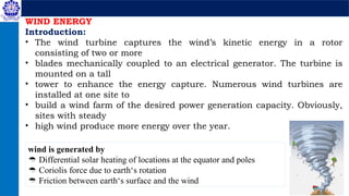
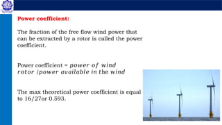
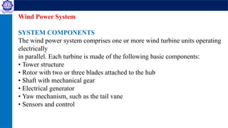
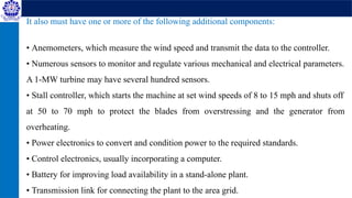
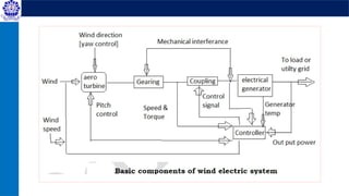
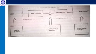
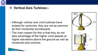
The document provides an overview of wind energy, explaining how wind turbines convert wind's kinetic energy into electricity through a rotor and generator system. It details the factors influencing wind energy production, such as wind speed, turbine design, and geographical location, emphasizing the need for effective control systems and the dynamics of wind flow. Additionally, it discusses the technical components of wind energy systems, including the mechanical and electrical parts necessary for efficient operation.


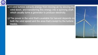
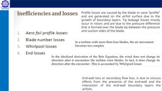
![The power in wind:
Wind possesses energy by virtue of its motion. There are 3 factors
determine the output from a wind energy converter, 1] the wind speed, 2]
The cross section of wind swept by rotor & 3] The overall conversion
efficiency of the rotor, transmission system & generator or pump.
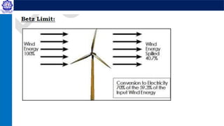
Only 1/3rd amount of air is decelerating by the rotors & 60% of the
available energy in wind into mechanical energy.
Well designed blades will typically extract 70% of the theoretical max,
but losses incurred in the gear box, transmission system & generator or
pump could decrease overall wind turbine efficiency to 35% or loss.
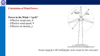
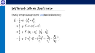
The power in the wind can be computed by using the concept of
kinetics. The wind mill works on the principle of converting kinetic energy
of the wind to mechanical energy.
Kinetic energy = k.E= ½ mv2 But m = ρAv
Available wind Power =Pa = 1/8 ρπD2
V3
........... Watts](https://image.slidesharecdn.com/non-conventionalenergyengineering2windenergy-250204172412-319bca6a/85/Non-Conventional-Energy-Engineering_2_Wind-Energy-pptx-10-320.jpg)
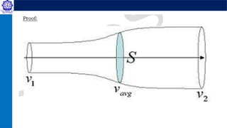

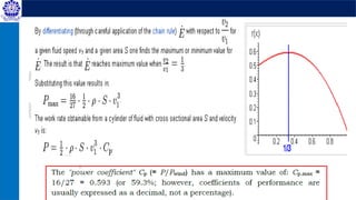
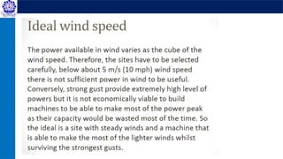
![Intuitively, the speed ratio of [V2/V1 = 0.333] between outgoing and incoming wind,
leaving at about a third of the speed it came in, would imply higher losses of kinetic
energy. But since a larger area is needed for slower-moving air, energy is conserved.
All energy entering the system is taken into consideration, and local "radial" kinetic
energy can have no effect on the outcome, which is the final energy state of the air
leaving the system, at a slower speed, larger area and accordingly its lower energy can
be calculated.
The last step in calculating the Betz efficiency Cp is to divide the calculated power
extracted from the flow by a reference power value. The Betz analysis uses for its power
reference, reasonably, the power of air upstream moving at V1 contained in a cylinder
with the cross-sectional area S of the rotor.
Understanding the Betz results](https://image.slidesharecdn.com/non-conventionalenergyengineering2windenergy-250204172412-319bca6a/85/Non-Conventional-Energy-Engineering_2_Wind-Energy-pptx-23-320.jpg)


![EEE 483[Wind Energy ,use of wind energy].pdf](https://cdn.slidesharecdn.com/ss_thumbnails/eee483windenergy-240506111938-7f084448-thumbnail.jpg?width=640&height=640&fit=bounds)