Downloaded 125 times

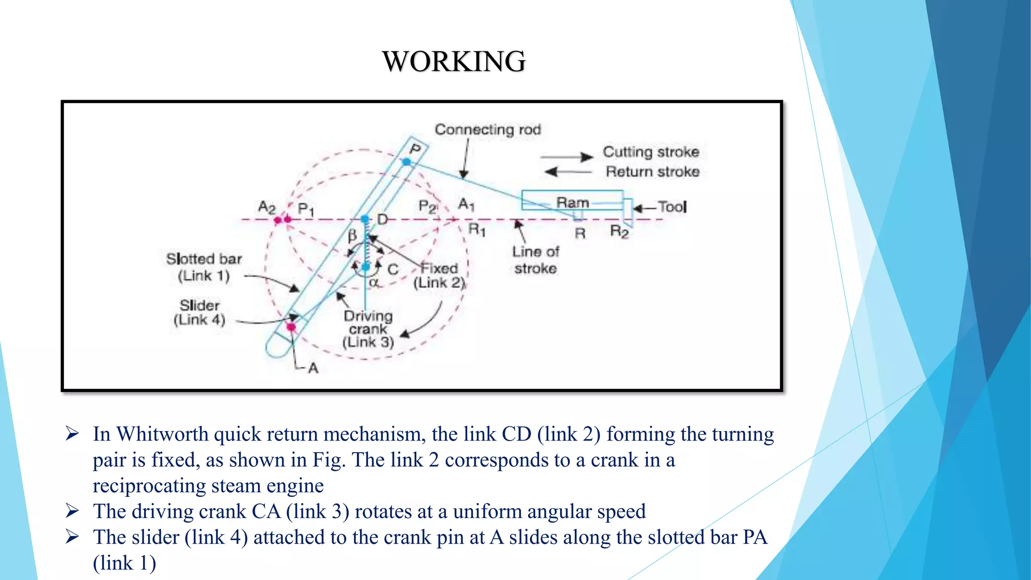
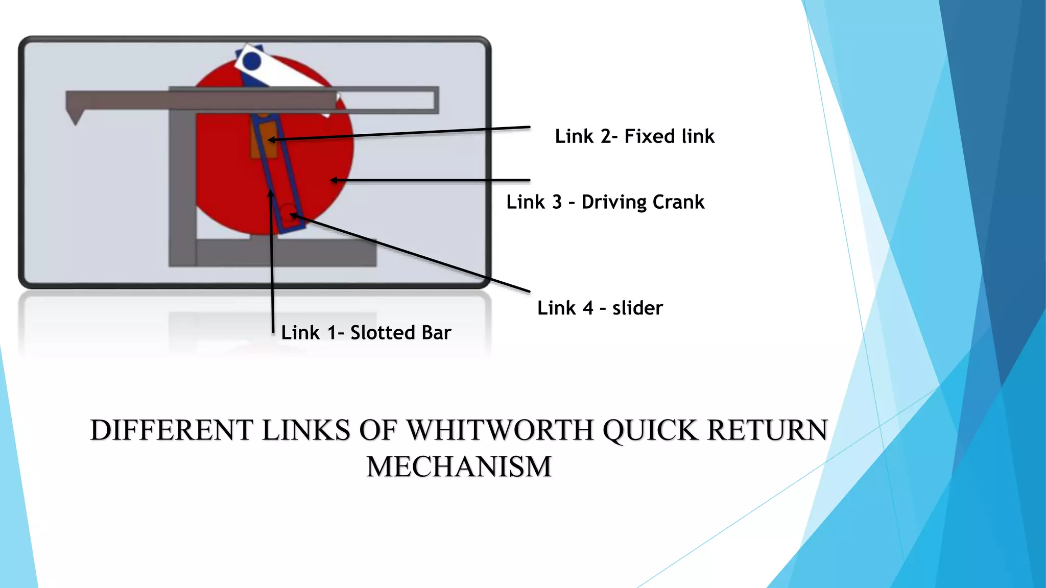
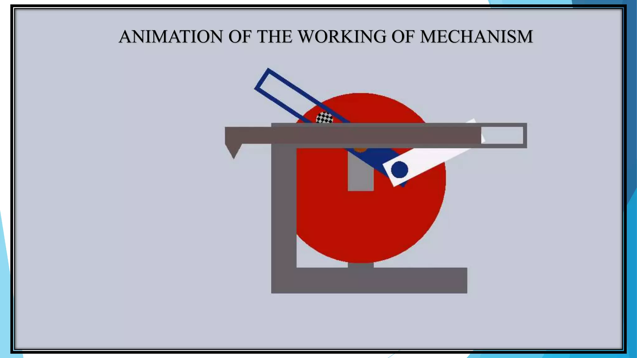
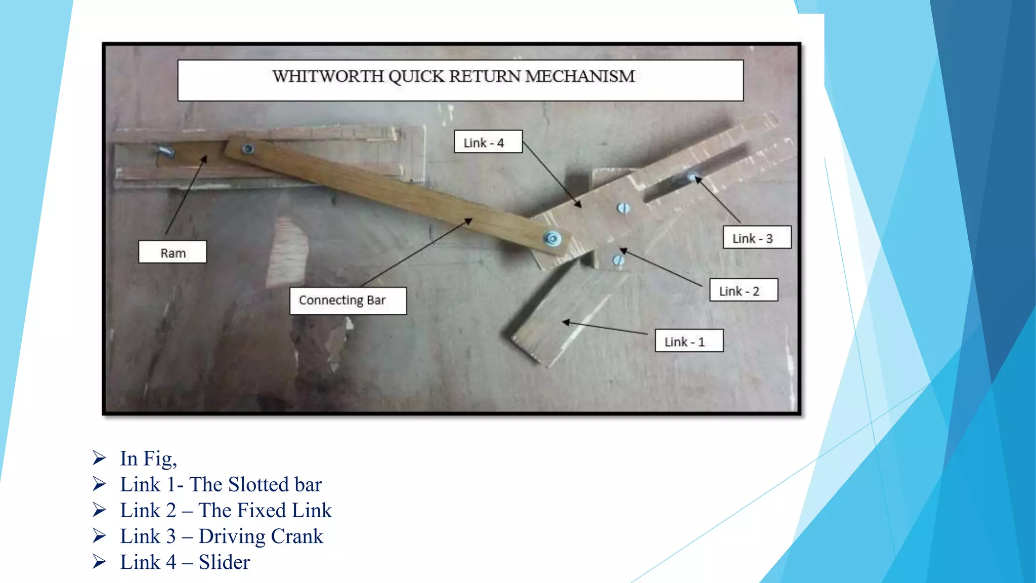
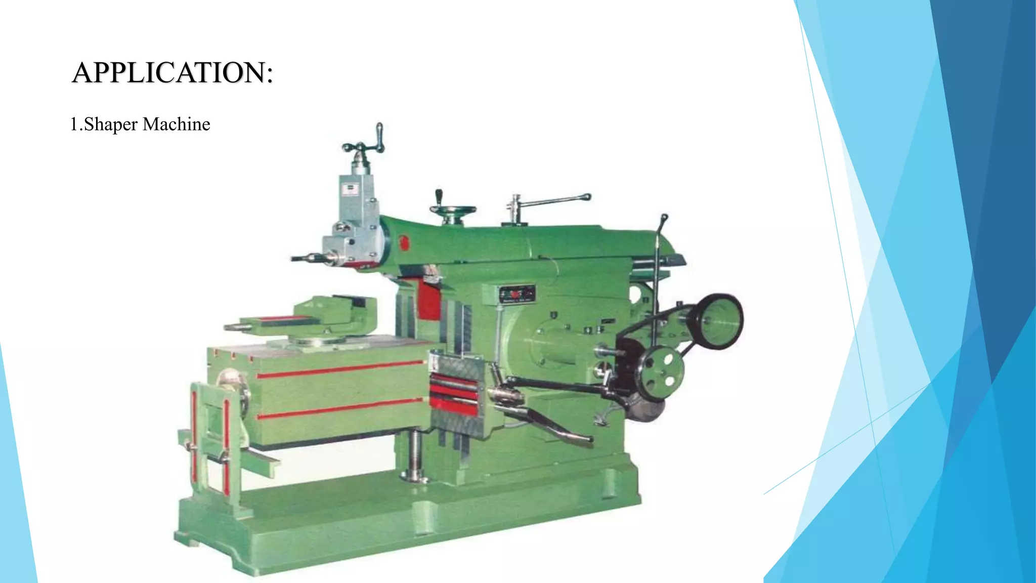
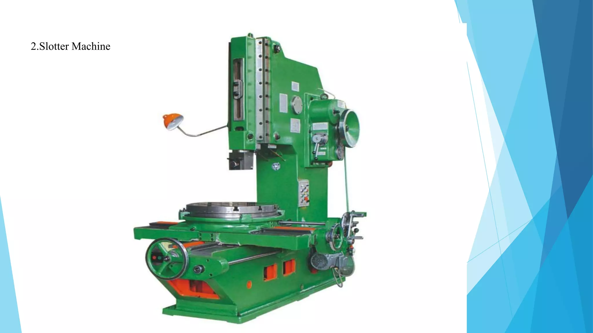


Sir Joseph Whitworth invented the Whitworth quick return mechanism in the 19th century to convert rotational motion into reciprocating linear motion. The mechanism uses four links - a fixed link, slotted bar, driving crank, and slider - to transform the rotation of a crank into the back-and-forth motion of a cutting tool. As the crank rotates clockwise and counterclockwise, the connected slider moves the tool across its stroke to shape or cut materials. This innovative mechanism is still used today in machine tools like shaper and slotter machines.


