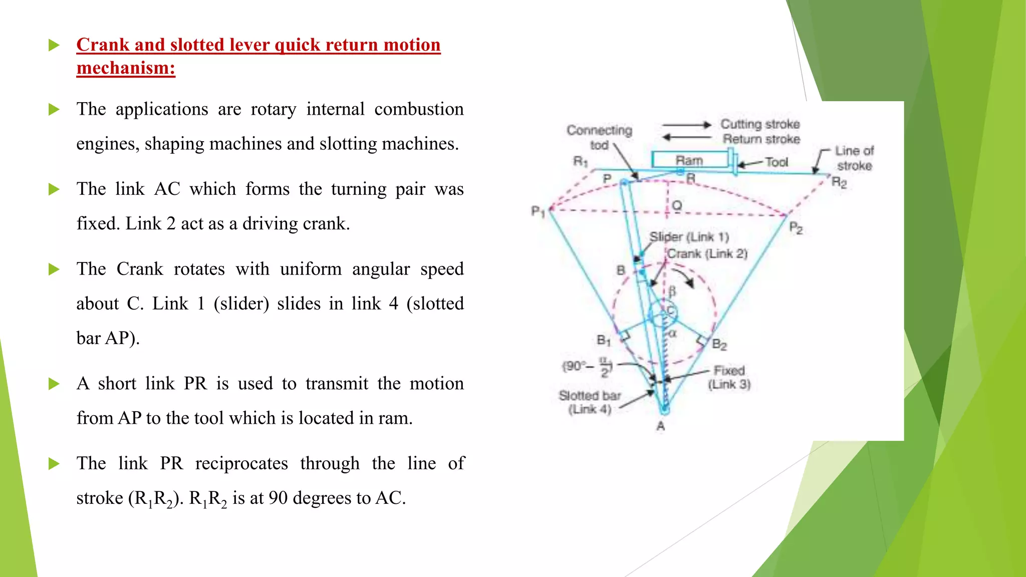
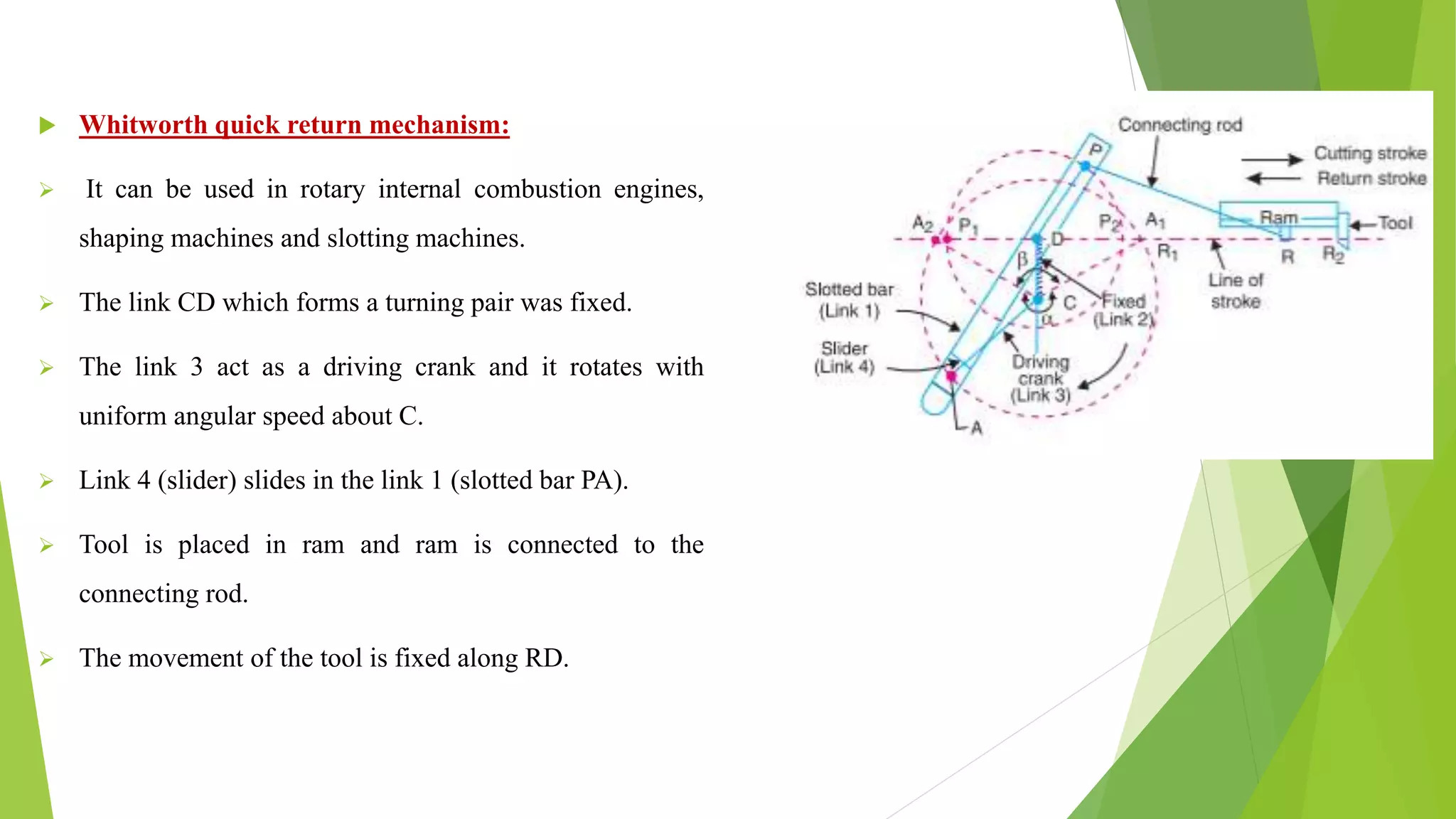
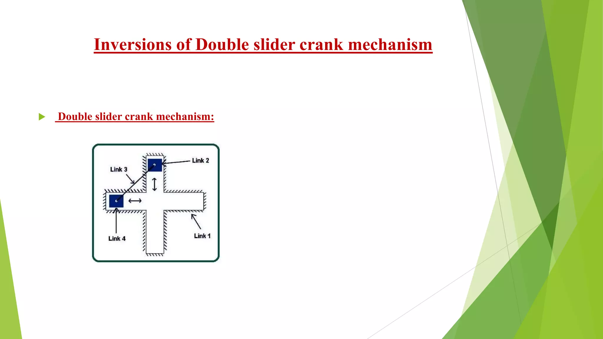
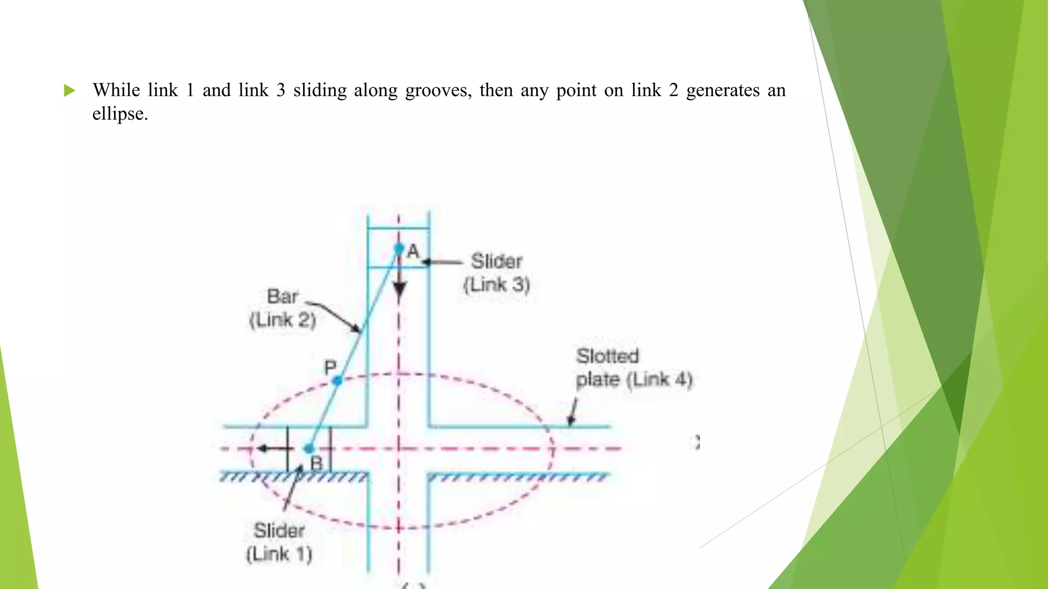
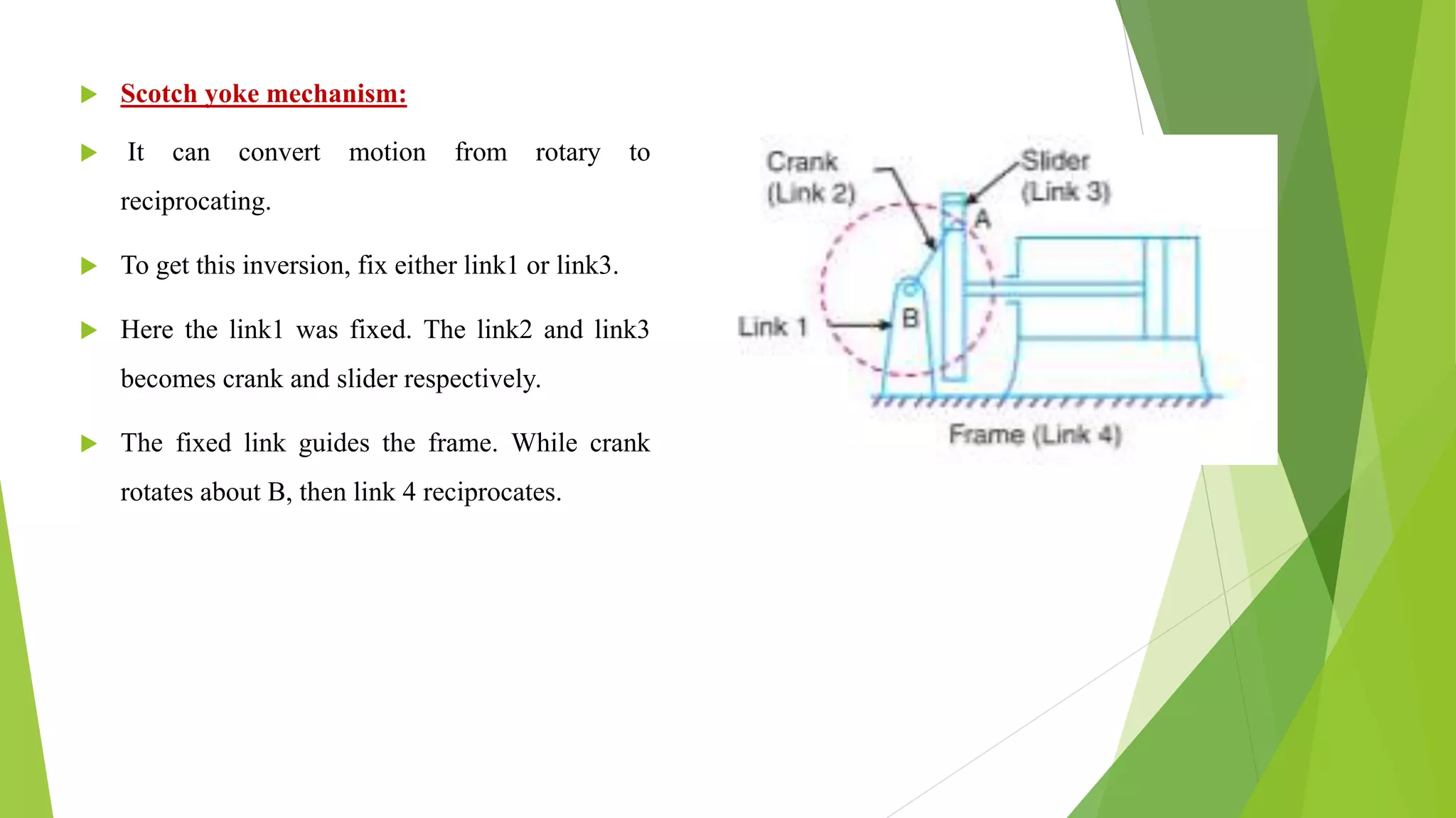
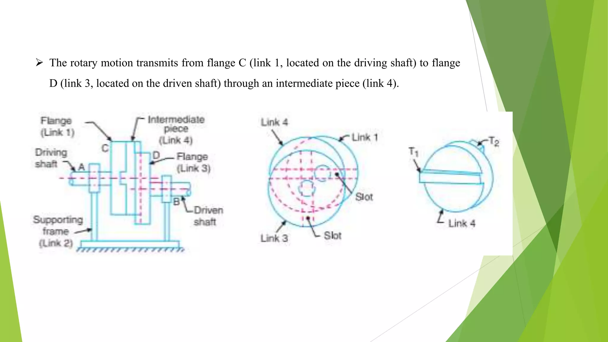
Inversions of Mechanism
Seminar and Technical writing (CR7998)
Spring (2020-21)
Course Instructor- Prof. Debasish Sarkar
Presented by
JAKKAMPUDI CHANDRIKA
520CR1002
Ph.D. Research Scholar
Department of Ceramic Engineering,
National Institute of Technology, Rourkela,
Odisha
Table of contents
 Introduction
 Inversions of four bar mechanism
 Inversions of single slider crank mechanism
 Inversions of double slider crank mechanism
 References
Introduction
 Kinematic link: Kinematic link is also called as an element. Kinematic link is a resistant
body which moves relative to other elements.
 Kinematic pair: Two Kinematic links which has contact between them form a Kinematic
pair. The two links are able to transform motion between them.
 Kinematic chain: Kinematic chain is an assembly of Kinematic pairs.
 Mechanism: Whenever one link of Kinematic chain fixed, that type of Kinematic chain
is called as mechanism. Mechanism is used to transmit motion.
 Machine: When a mechanism is used to transmit power or to do work, then it becomes
a machine.
 Mobility for Plane Mechanism (n): The number of independent input parameters
required to get the desired output from mechanism.
 Kutzbach’s criterion for n,
n = 3 (l – 1) – 2 j – h
j = Number of binary joints,
h = Number of higher pairs, and
l = Number of links.
 If n = zero, then the mechanism turns into a structure. There is absence of relative
motion among the links.
 If n = 1, then the mechanism needs a single input motion.
 If n = 2, then the mechanism needs two separate input motions
 If n≤-1, then the mechanism becomes statically indeterminate structure and redundant
constraints present in the Kinematic chain.
 Inversion of mechanism: The method of fixing different links in a Kinematic chain to
obtain different mechanisms is known as inversion of mechanism.
Inversions of four bar mechanism
 Four bar mechanism:
 Crank: The link which makes complete revolution relative to other links is called as crank.
It is also called as a driver.
 Lever: The link which undergoes oscillation or partial rotation is called as lever. It is also
called as rocker, follower.
 Coupler: The link which connects crank and rocker is known as coupler. It acts like a
connecting rod.
 Frame: It is a fixed link.
Crank and lever mechanism:
 If the link adjacent to the shortest link fixed, then
the shortest link rotates 360 degrees.
 The link opposite to shortest link oscillates and
forms crank-lever mechanism or crank-rocker
mechanism.
 In this case the sum of the shortest link length and
the longest link length is less than the sum of the
other two link’s length.
 Example: beam engine
Beam engine
Double crank mechanism:
 When the shortest link is fixed, then the links adjacent to the shortest link rotates 360
degrees and forms double crank mechanism.
 In this case, the sum of the lengths of the shortest link and the longest link is less than the
sum of the other 2 link’s length.
Parallelogram linkage mechanism:
Connecting rod of a locomotive
 In this case the sum of the shortest link length and the
longest link length is equal to the sum of the other 2
link’s length.
 Fix link 1 to get this mechanism. Link 2 and link 4
rotate 360 degrees.
 Example: Connecting rod of a locomotive
Double rocker mechanism:
 When the link opposite to the shortest
link fixed, then the links adjacent to
shortest link oscillates and forms
double-rocker mechanism.
 Example: Watt’s indicator mechanism
Inversions of single slider crank mechanism
 single slider crank mechanism:
 Pendulum pump or Bull engine:
 In this type of mechanism, the link 4 is fixed and link4
act as a cylinder.
 The link 2 rotates 360° and the link3 oscillates about a
pin located on the fixed link at A.
 The link2 is crank and link 3 is a connecting rod. The
link 1 is piston rod and piston reciprocates which is
attached to the piston rod.
 For duplex pump two pistons are attached to the link 1.
 Oscillating cylinder engine:
 It can convert the motion from
reciprocating to rotary.
 The link3 (the connecting rod) is fixed.
The link 2 rotates about a pin at one end of
the connecting rod.
 The link 1 is reciprocates and link 4
oscillates about the pin at other end of the
connecting rod.
 Rotary internal combustion engine:
 Currently, gas turbines are used instead
of rotary internal rotary combustion
engines in aviation.
 The Rotary internal combustion engine
has 7 cylinders in one plane.
 Cylinders revolve about a fixed centre.
The crank (link 2) is fixed.
 Link 4 (connecting rod) rotates, link 3
(piston) reciprocates inside the
cylinders (link1).
 Crank and slotted lever quick return motion
mechanism:
 The applications are rotary internal combustion
engines, shaping machines and slotting machines.
 The link AC which forms the turning pair was
fixed. Link 2 act as a driving crank.
 The Crank rotates with uniform angular speed
about C. Link 1 (slider) slides in link 4 (slotted
bar AP).
 A short link PR is used to transmit the motion
from AP to the tool which is located in ram.
 The link PR reciprocates through the line of
stroke (R1R2). R1R2 is at 90 degrees to AC.
 Whitworth quick return mechanism:
 It can be used in rotary internal combustion engines,
shaping machines and slotting machines.
 The link CD which forms a turning pair was fixed.
 The link 3 act as a driving crank and it rotates with
uniform angular speed about C.
 Link 4 (slider) slides in the link 1 (slotted bar PA).
 Tool is placed in ram and ram is connected to the
connecting rod.
 The movement of the tool is fixed along RD.
Inversions of Double slider crank mechanism
 Double slider crank mechanism:
 Elliptical trammel:
 Elliptical trammel can be used to draw ellipses.
 To get this inversion the slotted plate (link 4) should be fixed.
 Two straight grooves are made to cut along fixed plate.
 The two grooves are at 90 degrees angle.
 Link 1 and link 3 act as a slider and link 2 is the bar.
 While link 1 and link 3 sliding along grooves, then any point on link 2 generates an
ellipse.
 Scotch yoke mechanism:
 It can convert motion from rotary to
reciprocating.
 To get this inversion, fix either link1 or link3.
 Here the link1 was fixed. The link2 and link3
becomes crank and slider respectively.
 The fixed link guides the frame. While crank
rotates about B, then link 4 reciprocates.
 Oldham’s coupling:
 It can be used to couple the two shafts. The shafts has minor distance between them.
 To get this inversion, link 2 should be fixed.
 Flange C and Flange D connected at the ends of two shafts with the help of forging
method.
 Diametrical slots are present in each flange.
 Link 4 has diametrical projections (T1, T2) and these projections completely insert
through the slots of two flanges.
 The rotary motion transmits from flange C (link 1, located on the driving shaft) to flange
D (link 3, located on the driven shaft) through an intermediate piece (link 4).
References
 THEORY OF MACHINES BY R.S. KHURMI, J.K. GUPTA
 https://en.wikipedia.org/wiki/Four-bar_linkage
Inversions of Mechanism

Inversions of Mechanism

  • 1.
    Inversions of Mechanism Seminarand Technical writing (CR7998) Spring (2020-21) Course Instructor- Prof. Debasish Sarkar Presented by JAKKAMPUDI CHANDRIKA 520CR1002 Ph.D. Research Scholar Department of Ceramic Engineering, National Institute of Technology, Rourkela, Odisha
  • 2.
    Table of contents Introduction  Inversions of four bar mechanism  Inversions of single slider crank mechanism  Inversions of double slider crank mechanism  References
  • 3.
    Introduction  Kinematic link:Kinematic link is also called as an element. Kinematic link is a resistant body which moves relative to other elements.  Kinematic pair: Two Kinematic links which has contact between them form a Kinematic pair. The two links are able to transform motion between them.  Kinematic chain: Kinematic chain is an assembly of Kinematic pairs.
  • 4.
     Mechanism: Wheneverone link of Kinematic chain fixed, that type of Kinematic chain is called as mechanism. Mechanism is used to transmit motion.  Machine: When a mechanism is used to transmit power or to do work, then it becomes a machine.  Mobility for Plane Mechanism (n): The number of independent input parameters required to get the desired output from mechanism.  Kutzbach’s criterion for n, n = 3 (l – 1) – 2 j – h j = Number of binary joints, h = Number of higher pairs, and l = Number of links.
  • 5.
     If n= zero, then the mechanism turns into a structure. There is absence of relative motion among the links.  If n = 1, then the mechanism needs a single input motion.  If n = 2, then the mechanism needs two separate input motions  If n≤-1, then the mechanism becomes statically indeterminate structure and redundant constraints present in the Kinematic chain.  Inversion of mechanism: The method of fixing different links in a Kinematic chain to obtain different mechanisms is known as inversion of mechanism.
  • 6.
    Inversions of fourbar mechanism  Four bar mechanism:
  • 7.
     Crank: Thelink which makes complete revolution relative to other links is called as crank. It is also called as a driver.  Lever: The link which undergoes oscillation or partial rotation is called as lever. It is also called as rocker, follower.  Coupler: The link which connects crank and rocker is known as coupler. It acts like a connecting rod.  Frame: It is a fixed link. Crank and lever mechanism:
  • 8.
     If thelink adjacent to the shortest link fixed, then the shortest link rotates 360 degrees.  The link opposite to shortest link oscillates and forms crank-lever mechanism or crank-rocker mechanism.  In this case the sum of the shortest link length and the longest link length is less than the sum of the other two link’s length.  Example: beam engine
  • 9.
  • 10.
    Double crank mechanism: When the shortest link is fixed, then the links adjacent to the shortest link rotates 360 degrees and forms double crank mechanism.  In this case, the sum of the lengths of the shortest link and the longest link is less than the sum of the other 2 link’s length.
  • 11.
    Parallelogram linkage mechanism: Connectingrod of a locomotive  In this case the sum of the shortest link length and the longest link length is equal to the sum of the other 2 link’s length.  Fix link 1 to get this mechanism. Link 2 and link 4 rotate 360 degrees.  Example: Connecting rod of a locomotive
  • 12.
    Double rocker mechanism: When the link opposite to the shortest link fixed, then the links adjacent to shortest link oscillates and forms double-rocker mechanism.  Example: Watt’s indicator mechanism
  • 13.
    Inversions of singleslider crank mechanism  single slider crank mechanism:
  • 14.
     Pendulum pumpor Bull engine:  In this type of mechanism, the link 4 is fixed and link4 act as a cylinder.  The link 2 rotates 360° and the link3 oscillates about a pin located on the fixed link at A.  The link2 is crank and link 3 is a connecting rod. The link 1 is piston rod and piston reciprocates which is attached to the piston rod.  For duplex pump two pistons are attached to the link 1.
  • 15.
     Oscillating cylinderengine:  It can convert the motion from reciprocating to rotary.  The link3 (the connecting rod) is fixed. The link 2 rotates about a pin at one end of the connecting rod.  The link 1 is reciprocates and link 4 oscillates about the pin at other end of the connecting rod.
  • 16.
     Rotary internalcombustion engine:  Currently, gas turbines are used instead of rotary internal rotary combustion engines in aviation.  The Rotary internal combustion engine has 7 cylinders in one plane.  Cylinders revolve about a fixed centre. The crank (link 2) is fixed.  Link 4 (connecting rod) rotates, link 3 (piston) reciprocates inside the cylinders (link1).
  • 17.
     Crank andslotted lever quick return motion mechanism:  The applications are rotary internal combustion engines, shaping machines and slotting machines.  The link AC which forms the turning pair was fixed. Link 2 act as a driving crank.  The Crank rotates with uniform angular speed about C. Link 1 (slider) slides in link 4 (slotted bar AP).  A short link PR is used to transmit the motion from AP to the tool which is located in ram.  The link PR reciprocates through the line of stroke (R1R2). R1R2 is at 90 degrees to AC.
  • 18.
     Whitworth quickreturn mechanism:  It can be used in rotary internal combustion engines, shaping machines and slotting machines.  The link CD which forms a turning pair was fixed.  The link 3 act as a driving crank and it rotates with uniform angular speed about C.  Link 4 (slider) slides in the link 1 (slotted bar PA).  Tool is placed in ram and ram is connected to the connecting rod.  The movement of the tool is fixed along RD.
  • 19.
    Inversions of Doubleslider crank mechanism  Double slider crank mechanism:
  • 20.
     Elliptical trammel: Elliptical trammel can be used to draw ellipses.  To get this inversion the slotted plate (link 4) should be fixed.  Two straight grooves are made to cut along fixed plate.  The two grooves are at 90 degrees angle.  Link 1 and link 3 act as a slider and link 2 is the bar.
  • 21.
     While link1 and link 3 sliding along grooves, then any point on link 2 generates an ellipse.
  • 22.
     Scotch yokemechanism:  It can convert motion from rotary to reciprocating.  To get this inversion, fix either link1 or link3.  Here the link1 was fixed. The link2 and link3 becomes crank and slider respectively.  The fixed link guides the frame. While crank rotates about B, then link 4 reciprocates.
  • 23.
     Oldham’s coupling: It can be used to couple the two shafts. The shafts has minor distance between them.  To get this inversion, link 2 should be fixed.  Flange C and Flange D connected at the ends of two shafts with the help of forging method.  Diametrical slots are present in each flange.  Link 4 has diametrical projections (T1, T2) and these projections completely insert through the slots of two flanges.
  • 24.
     The rotarymotion transmits from flange C (link 1, located on the driving shaft) to flange D (link 3, located on the driven shaft) through an intermediate piece (link 4).
  • 25.
    References  THEORY OFMACHINES BY R.S. KHURMI, J.K. GUPTA  https://en.wikipedia.org/wiki/Four-bar_linkage