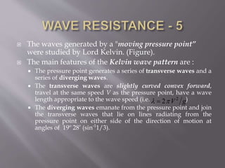
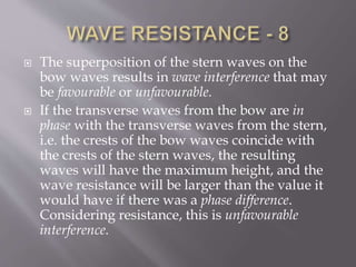
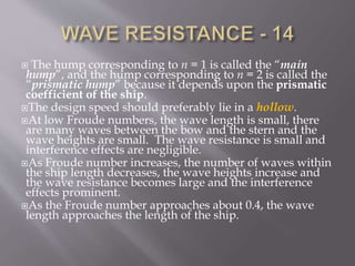
This document discusses wave resistance in ships. It explains that wave resistance increases significantly at high speeds as waves generated by the ship grow larger. It also describes how the interference of bow and stern waves can result in either favorable or unfavorable wave patterns depending on their phase relationship. Finally, it discusses how ship speed is ideally operated in a "hollow" of the wave resistance curve where interference is favorable and resistance is lower.
The ship at sea or lying in still water is constantly being subjected to a wide variety of stresses and strains, which result from the action of forces from outside and within the ship.
propulsion engineering-02-resistance of shipsfahrenheit
propulsion engineering-02-resistance of shipsMarine Engineering (Marine Propulsion)
This program is designed for those students who want training in marine gasoline and diesel engines without immediately
pursuing the Associate in Science degree. The certificate is issued by the Marine Engineering Department and attests to
the completion of the courses outlined below. These courses may also apply to the A.S. degree in Marine Engineering if a
student later decides on that option. Program duration is one (1) calendar year.
Gasoline Engines (9 credits required)
MTE 1053C 2 & 4-Cycle Outboard Engine Repair & Maintenance (3)
MTE 1166C Marine Ignition and Fuel Systems (3)
MTE 2072C Marine Propulsion Gasoline Engine Troubleshooting (3)
Diesel Engines (12 credits required)
MTE 1001C Marine Diesel Engine Overhaul (3)
MTE 1056C Marine Diesel Systems (3)
MTE 2058C Diesel Engine Testing Troubleshooting Procedures (3)
MTE 2160C Diesel Fuel Injection Systems (3)
Program Core (Choose 4)
MTE 1183C Marine Engine Installation and Repowering Procedures (3) |
MTE 1400C Applied Marine Electricity (3)
MTE 1651C Gas & Electric Welding (3)
MTE 2054C Marine 4-Cycle Stern Drive Inboard Engines (3)
MTE 2062 Marine Corrosion and Corrosion Prevention (2)
MTE 2234C Marine Gearcase, Outdrives and Transmission System (4)
Total Credits Required: 32/34
Optional Factory Certifications:
Bombardier/Evinrude Marine:
° Evinrude E-Tec Outboards
° Evinrude E-Tech V Models
Mercury Marine:
° Propeller 1
° Corrosion 1
° Hydraulics
° Smart Craft 1
° Fuels and Lubes
° Fuel II
° Electrical II
° Navigating DDT
° Outboard Rigging
° Mercruiser EFI System
State of Florida :
° Safe Boating
° Livery Certification
Other Optional Certificatios:
° USCG Captains License
° American Welding Society, Welding Certifications
° FKCC Welding Certification
Waves _______________________ (Name) How do ocea.docxmelbruce90096
Waves
_______________________
(Name)
How do ocean waves form?
“All waves are disturbances of a fluid medium through which energy is moved” (Davis,
1997). Ocean waves travel on the interface between oceans and the atmosphere, and are
produced most commonly by winds. As shown in Figure 1, the crest of a wave is its highest
point while the trough is the lowest. The height of the wave is the vertical distance between the
crest and the trough. The wavelength (λ) is the horizontal distance from crest to crest or from
trough to trough. The steepness is the ratio of its height to λ. When the steepness value reaches
0.143 (i.e., a ratio of 1:7), the crest of the wave breaks. Note that a steepness value less than
0.143 means a stable wave while one larger than 0.143 means an unstable breaking wave.
Figure 1. Key characteristics used to describe ocean waves.
Using Figure 1, please answer all of the following questions.
(1) What is the height of the illustrated wave?
(2) What is the wavelength?
(3) What is the steepness?
(4) Will the wave break given your answer to question (3)? Please briefly explain
your answer.
Using Figure 2, use two different colored pencils and sketch two waves:
Wave “A” has a height of 2 m and a wavelength of 10 m.
Wave “B” has a height of 4m and a wavelength of 6m.
For each wave, label the wavelength, wave height, crest, and trough.
Figure 2. A grid for drawing a wave.
(5) What is the steepness of wave A that you sketched?
(6) Will wave A break?
(7) What is the steepness of wave B that you sketched?
(8) Will wave B break?
When the interface between the oceans and the atmosphere is disturbed by a force, then
waves form. Most commonly that disturbing force is the friction of the wind moving across the
water. Once the wave has formed gravity acts against this disturbance, and attempts to restore the
water/atmosphere interface back to its flat-water position (i.e., a horizontal state). Hence, wind-
generated waves are sometimes referred to as gravity waves. As gravity pulls the crest of a wave
downward, momentum carries the water/atmosphere interface beyond the flat-water position to
form a trough. As a result, a buoy will appear to move up and down without being translated in
the direction that the waves appear to be moving. Such up and down motion will continue as
along as the wind is blowing. When the wind stops blowing, the water/atmosphere interface
returns to its normal flat-water state.
The period of a wave is the time it takes for one wavelength to pass a reference mark.
The periods for normal ocean waves range from a few seconds to about 15 seconds. Note that
this differs from wave celerity which is the speed at which a wave advances or propagates. Deep
water waves are waves that occur in water depth that is greater than one half their wavelength.
(9) If it takes 10 seconds for 1 wavelength.
Immunizing Image Classifiers Against Localized Adversary Attacksgerogepatton
This paper addresses the vulnerability of deep learning models, particularly convolutional neural networks
(CNN)s, to adversarial attacks and presents a proactive training technique designed to counter them. We
introduce a novel volumization algorithm, which transforms 2D images into 3D volumetric representations.
When combined with 3D convolution and deep curriculum learning optimization (CLO), itsignificantly improves
the immunity of models against localized universal attacks by up to 40%. We evaluate our proposed approach
using contemporary CNN architectures and the modified Canadian Institute for Advanced Research (CIFAR-10
and CIFAR-100) and ImageNet Large Scale Visual Recognition Challenge (ILSVRC12) datasets, showcasing
accuracy improvements over previous techniques. The results indicate that the combination of the volumetric
input and curriculum learning holds significant promise for mitigating adversarial attacks without necessitating
adversary training.
Water scarcity is the lack of fresh water resources to meet the standard water demand. There are two type of water scarcity. One is physical. The other is economic water scarcity.
Cosmetic shop management system project report.pdfKamal Acharya
Buying new cosmetic products is difficult. It can even be scary for those who have sensitive skin and are prone to skin trouble. The information needed to alleviate this problem is on the back of each product, but it's thought to interpret those ingredient lists unless you have a background in chemistry.
Instead of buying and hoping for the best, we can use data science to help us predict which products may be good fits for us. It includes various function programs to do the above mentioned tasks.
Data file handling has been effectively used in the program.
The automated cosmetic shop management system should deal with the automation of general workflow and administration process of the shop. The main processes of the system focus on customer's request where the system is able to search the most appropriate products and deliver it to the customers. It should help the employees to quickly identify the list of cosmetic product that have reached the minimum quantity and also keep a track of expired date for each cosmetic product. It should help the employees to find the rack number in which the product is placed.It is also Faster and more efficient way.
NO1 Uk best vashikaran specialist in delhi vashikaran baba near me online vas...Amil Baba Dawood bangali
Contact with Dawood Bhai Just call on +92322-6382012 and we'll help you. We'll solve all your problems within 12 to 24 hours and with 101% guarantee and with astrology systematic. If you want to take any personal or professional advice then also you can call us on +92322-6382012 , ONLINE LOVE PROBLEM & Other all types of Daily Life Problem's.Then CALL or WHATSAPP us on +92322-6382012 and Get all these problems solutions here by Amil Baba DAWOOD BANGALI
#vashikaranspecialist #astrologer #palmistry #amliyaat #taweez #manpasandshadi #horoscope #spiritual #lovelife #lovespell #marriagespell#aamilbabainpakistan #amilbabainkarachi #powerfullblackmagicspell #kalajadumantarspecialist #realamilbaba #AmilbabainPakistan #astrologerincanada #astrologerindubai #lovespellsmaster #kalajaduspecialist #lovespellsthatwork #aamilbabainlahore#blackmagicformarriage #aamilbaba #kalajadu #kalailam #taweez #wazifaexpert #jadumantar #vashikaranspecialist #astrologer #palmistry #amliyaat #taweez #manpasandshadi #horoscope #spiritual #lovelife #lovespell #marriagespell#aamilbabainpakistan #amilbabainkarachi #powerfullblackmagicspell #kalajadumantarspecialist #realamilbaba #AmilbabainPakistan #astrologerincanada #astrologerindubai #lovespellsmaster #kalajaduspecialist #lovespellsthatwork #aamilbabainlahore #blackmagicforlove #blackmagicformarriage #aamilbaba #kalajadu #kalailam #taweez #wazifaexpert #jadumantar #vashikaranspecialist #astrologer #palmistry #amliyaat #taweez #manpasandshadi #horoscope #spiritual #lovelife #lovespell #marriagespell#aamilbabainpakistan #amilbabainkarachi #powerfullblackmagicspell #kalajadumantarspecialist #realamilbaba #AmilbabainPakistan #astrologerincanada #astrologerindubai #lovespellsmaster #kalajaduspecialist #lovespellsthatwork #aamilbabainlahore #Amilbabainuk #amilbabainspain #amilbabaindubai #Amilbabainnorway #amilbabainkrachi #amilbabainlahore #amilbabaingujranwalan #amilbabainislamabad
About
Indigenized remote control interface card suitable for MAFI system CCR equipment. Compatible for IDM8000 CCR. Backplane mounted serial and TCP/Ethernet communication module for CCR remote access. IDM 8000 CCR remote control on serial and TCP protocol.
• Remote control: Parallel or serial interface.
• Compatible with MAFI CCR system.
• Compatible with IDM8000 CCR.
• Compatible with Backplane mount serial communication.
• Compatible with commercial and Defence aviation CCR system.
• Remote control system for accessing CCR and allied system over serial or TCP.
• Indigenized local Support/presence in India.
• Easy in configuration using DIP switches.
Technical Specifications
Indigenized remote control interface card suitable for MAFI system CCR equipment. Compatible for IDM8000 CCR. Backplane mounted serial and TCP/Ethernet communication module for CCR remote access. IDM 8000 CCR remote control on serial and TCP protocol.
Key Features
Indigenized remote control interface card suitable for MAFI system CCR equipment. Compatible for IDM8000 CCR. Backplane mounted serial and TCP/Ethernet communication module for CCR remote access. IDM 8000 CCR remote control on serial and TCP protocol.
• Remote control: Parallel or serial interface
• Compatible with MAFI CCR system
• Copatiable with IDM8000 CCR
• Compatible with Backplane mount serial communication.
• Compatible with commercial and Defence aviation CCR system.
• Remote control system for accessing CCR and allied system over serial or TCP.
• Indigenized local Support/presence in India.
Application
• Remote control: Parallel or serial interface.
• Compatible with MAFI CCR system.
• Compatible with IDM8000 CCR.
• Compatible with Backplane mount serial communication.
• Compatible with commercial and Defence aviation CCR system.
• Remote control system for accessing CCR and allied system over serial or TCP.
• Indigenized local Support/presence in India.
• Easy in configuration using DIP switches.
Hierarchical Digital Twin of a Naval Power SystemKerry Sado
A hierarchical digital twin of a Naval DC power system has been developed and experimentally verified. Similar to other state-of-the-art digital twins, this technology creates a digital replica of the physical system executed in real-time or faster, which can modify hardware controls. However, its advantage stems from distributing computational efforts by utilizing a hierarchical structure composed of lower-level digital twin blocks and a higher-level system digital twin. Each digital twin block is associated with a physical subsystem of the hardware and communicates with a singular system digital twin, which creates a system-level response. By extracting information from each level of the hierarchy, power system controls of the hardware were reconfigured autonomously. This hierarchical digital twin development offers several advantages over other digital twins, particularly in the field of naval power systems. The hierarchical structure allows for greater computational efficiency and scalability while the ability to autonomously reconfigure hardware controls offers increased flexibility and responsiveness. The hierarchical decomposition and models utilized were well aligned with the physical twin, as indicated by the maximum deviations between the developed digital twin hierarchy and the hardware.
Industrial Training at Shahjalal Fertilizer Company Limited (SFCL)MdTanvirMahtab2
This presentation is about the working procedure of Shahjalal Fertilizer Company Limited (SFCL). A Govt. owned Company of Bangladesh Chemical Industries Corporation under Ministry of Industries.
Explore the innovative world of trenchless pipe repair with our comprehensive guide, "The Benefits and Techniques of Trenchless Pipe Repair." This document delves into the modern methods of repairing underground pipes without the need for extensive excavation, highlighting the numerous advantages and the latest techniques used in the industry.
Learn about the cost savings, reduced environmental impact, and minimal disruption associated with trenchless technology. Discover detailed explanations of popular techniques such as pipe bursting, cured-in-place pipe (CIPP) lining, and directional drilling. Understand how these methods can be applied to various types of infrastructure, from residential plumbing to large-scale municipal systems.
Ideal for homeowners, contractors, engineers, and anyone interested in modern plumbing solutions, this guide provides valuable insights into why trenchless pipe repair is becoming the preferred choice for pipe rehabilitation. Stay informed about the latest advancements and best practices in the field.
Gen AI Study Jams _ For the GDSC Leads in India.pdf
Wave resistance
1.
2. There are two main components of resistance
Viscous resistance
Wave resistance
Wave resistance is associated with the waves
generated by a ship alone.
At low speeds (Froude numbers), wave
resistance is a small part of total resistance.
3. At very high speeds (Fn more than about 0.45),
wave resistance increases so much that
conventional displacement type vessels cannot
go at such high speeds.
It is necessary to use unconventional hull
forms for ships of very high speed.
4. A three-dimensional body moving in water has
a pressure distribution around it.
In case of a ship, the free surface will rise at
regions of high pressure and fall at regions of
low pressure.
A moving pressure distribution will give rise to
free surface waves accompanying the body.
This was observed by W. Froude, who made a
sketch showing the waves generated by a ship.
5.
6. The waves generated by a "moving pressure point”
were studied by Lord Kelvin. (Figure).
The main features of the Kelvin wave pattern are :
The pressure point generates a series of transverse waves and a
series of diverging waves.
The transverse waves are slightly curved convex forward,
travel at the same speed V as the pressure point, have a wave
length appropriate to the wave speed (i.e. )
The diverging waves emanate from the pressure point and join
the transverse waves that lie on lines radiating from the
pressure point on either side of the direction of motion at
angles of 19o
28’ (sin-1
1/3).
2
2 V g
7.
8. The waves generated by a ship in calm water have the
similar features.
The moving pressure distribution of the ship can be
regarded as an assembly of pressure points all
producing Kelvin wave patterns that are superposed
on each other.
There is a bow wave system and a stern wave system,
each with diverging and transverse waves (Figure) :
Each system lies within lines making an angle with direction of
motion; the angle depends on the hull form.
The bow transverse waves start with a crest aft of the bow.
The stern transverse waves start with a trough forward of the
stern.
The stern wave system is superimposed on the bow wave
system.
Diverging waves are steeper and therefore more visible.
The combined wave system spreads far and wide behind the
ship with the wave heights reducing and finally dying out.
9.
10.
11. The superposition of the stern waves on the
bow waves results in wave interference that may
be favourable or unfavourable.
If the transverse waves from the bow are in
phase with the transverse waves from the stern,
i.e. the crests of the bow waves coincide with
the crests of the stern waves, the resulting
waves will have the maximum height, and the
wave resistance will be larger than the value it
would have if there was a phase difference.
Considering resistance, this is unfavourable
interference.
12. If the bow waves and the stern waves are
completely out of phase, i.e. the crests of the
bow waves coincide with the troughs of the
stern waves, the resulting waves have smaller
heights and the wave resistance is lower :
favourable interference.
Wave resistance does not increase steadily with
speed but has undulations. This is shown
clearly by a curve of wave resistance coefficient
as a function of Froude number, or a curve of
total resistance coefficient as a function of speed-
length ratio , V in knots, L in feet.
/V L
13.
14. The “humps and hollows” in a wave resistance
curve can also be explained by noting that a
deep wave trough at the stern will cause a
sharp increase in pressure resistance, while a
shallow trough or a crest will reduce the
pressure resistance, which is mostly wave
resistance. (Figure).
The speeds or Froude numbers at which
favourable and unfavourable wave interference
(humps and hollows) occur can be calculated.
15.
16. mL = distance between first crest of bow transverse
waves and first crest of stern transverse waves.
n = number of complete wave lengths in the distance mL
Values of Froude number, Fn
Hump Hollow Hump Hollow
n Speed Speed n Speed Speed
1 0.520 0.736 6 0.212 0.222
2 0.368 0.425 7 0.197 0.204
3 0.300 0.329 8 0.184 0.190
4 0.260 0.278 9 0.173 0.178
5 0.233 0.245 10 0.164 0.169
(Figure)
17. The hump corresponding to n = 1 is called the “main
hump”, and the hump corresponding to n = 2 is called the
“prismatic hump” because it depends upon the prismatic
coefficient of the ship.
The design speed should preferably lie in a hollow.
At low Froude numbers, the wave length is small, there
are many waves between the bow and the stern and the
wave heights are small. The wave resistance is small and
interference effects are negligible.
As Froude number increases, the number of waves within
the ship length decreases, the wave heights increase and
the wave resistance becomes large and the interference
effects prominent.
As the Froude number approaches about 0.4, the wave
length approaches the length of the ship.
18. Above a Froude number of 0.4, the wave length becomes
greater than the length of the ship, the first trough of the
bow waves starts nearing the stern, there is a large
decrease in pressure, particularly towards aft, resulting in
sinkage and aft trim, and a large increase in wave
resistance.
These effects reach their peak at Froude numbers around
0.5 (main hump). The sharp increase in wave resistance at
Froude numbers above 0.4 acts as a speed barrier for ships
of normal form and unconventional hull forms must be
used.
19. Wave breaking resistance is closely related to wave
making resistance.
In ships with very full forebodies, the flow ahead of the
bow becomes unstable and the bow waves break resulting
in wave breaking resistance.
Wave breaking may be due to flow separation at the free
surface ahead of the bow.
Another view is that wave breaking occurs when the
streamlines at the bow have excessive curvature causing
flow instability.
Guidelines for avoiding wave breaking include making
the radius of curvature of the streamlines sufficiently large
(R>V2
/50, metric units), and limiting the half angle of
entrance and the slope of the tangent to the sectional area
curve at the forward end within limits.
Wave breaking resistance is not important for most ships.
20.
21. Appendages :
Single screw ships : rudder, bilge keels and stabiliser
fins, skeg
Twin screw ships : shaft brackets or bossings, open
shafts, multiple rudders
“Negative appendages” : projections into the hull,
e.g. tunnels of lateral thrust units
22. Appendage resistance from model tests :
Appendage resistance = total resistance with
appendages – bare hull total resistance
Difficulties:
Accuracy of small appendages such as bilge keels
Scaling problems : Reynolds number effects, laminar
flow
Appendage scale factor
23. Propulsion devices and their components not
considered as appendages
Rudders in propeller slipstream
Empirical formulas for resistance of individual
appendages
Preliminary estimates of appendage resistance
as a percentage of total bare hull resistance
24. APPENDAGE RESISTANCE AS
PERCENTAGE OF BARE HULL RESISTANCE
Type of ship Values of Froude number
0.21 0.30 0.48
Large, fast, four screws 10-16 10-16 -
Small, fast, twin screws 20-30 17-25 10-15
Small, medium speed, twin screws 12-30 10-23 -
Large, medium speed, twin screws 8-14 8-14 -
All single screw ships 2 - 5 2 - 5 -
25. Air and wind resistance RAA : D.W. Taylor’s
formula :
CD is the drag coefficient
is the density of air
AT is the transverse projected area of the ship above
water
VR is the relative head wind speed
Typically CD = 1.2, = 1.225 kg per m3
1 2
2AA D air T RR C A V
air
air
26. Hughes method (slightly modified) to
determine RAA :
Wind force
VR = relative wind velocity
= relative wind direction
AL = longitudinal above water projected area
AT = transverse above water projected area
= angle of wind force to ship centre line
1 2 2
2
1 2 2
2
cos cos
sin sin
D air T R
D air L R
F C A V
F C A V
27.
28. Effect of wind velocity gradient – depends
upon relative magnitudes of ship speed and
absolute wind speed
Yawing moment if centre of pressure of wind
force and centre of lateral resistance have a
large longitudinal separation : resulting drift
angle and use of rudder increase
hydrodynamic resistance
Air and wind resistance may be reduced by
streamlining superstructure and deck houses –
but this works only in a head wind.