Download as PDF, PPTX

![Wave Propagation Models
Basic Principle – Breakpoint
130
• Free space: Two path model
Free space model
received power ~ 1 / d2
120
20 dB / decade
• No longer valid from 110
a certain distance on Path Loss [dB]
• After breakpoint:
100
received power ~ 1 / d4
40 dB / decade
90
• Deduced from 80
two-path model, i.e.
superposition of direct 70
and ground-reflected rays:
0,1 0,3 1,0 3,16 10,0
BP = 4htxhrx/ Distance [km]
Loss for 900 MHz and Tx height of 30m (Rx height 1.5m)
breakpoint distance = 1.7 km
© by AWE Communications GmbH 8](https://image.slidesharecdn.com/wavepropagationmodels-120920010922-phpapp01/75/Wave-propagationmodels-8-2048.jpg)
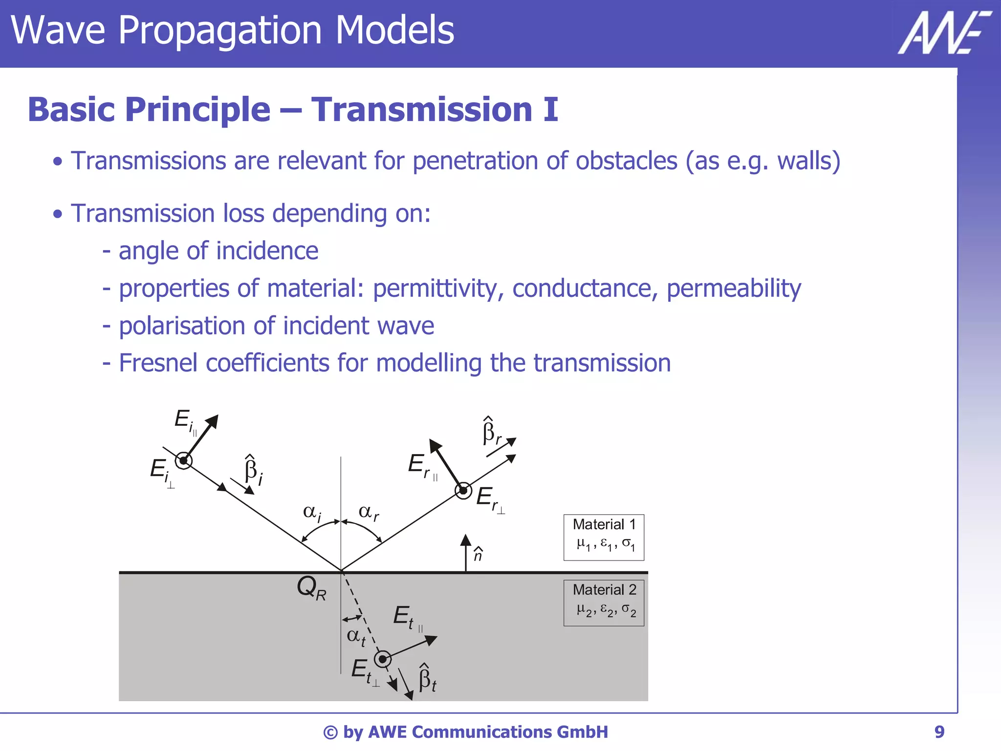
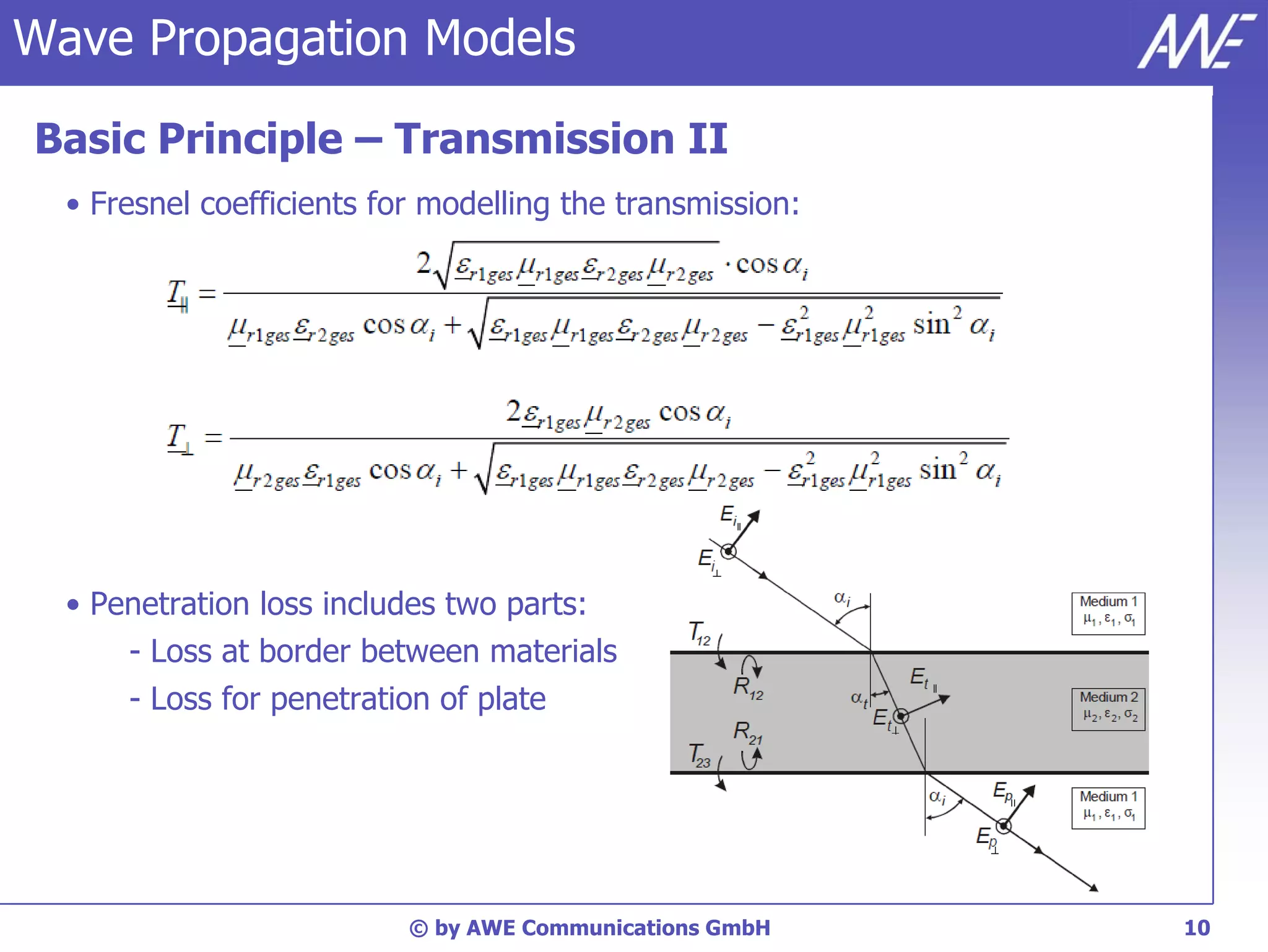
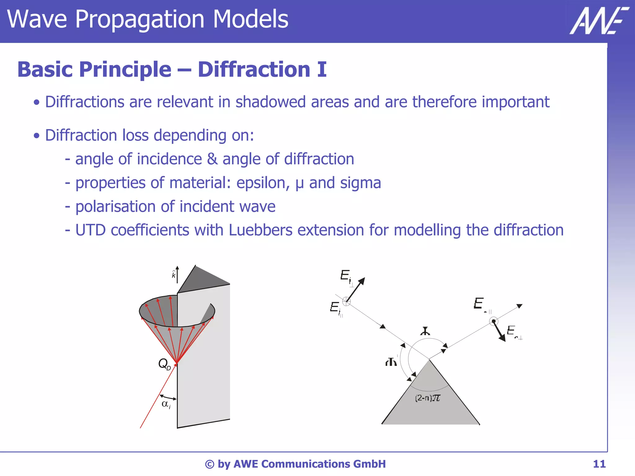
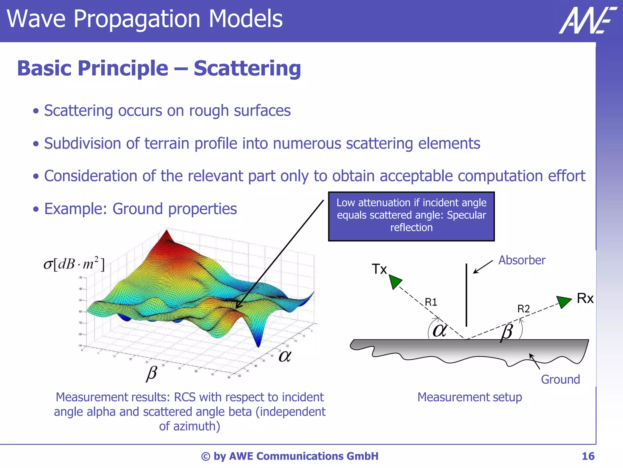
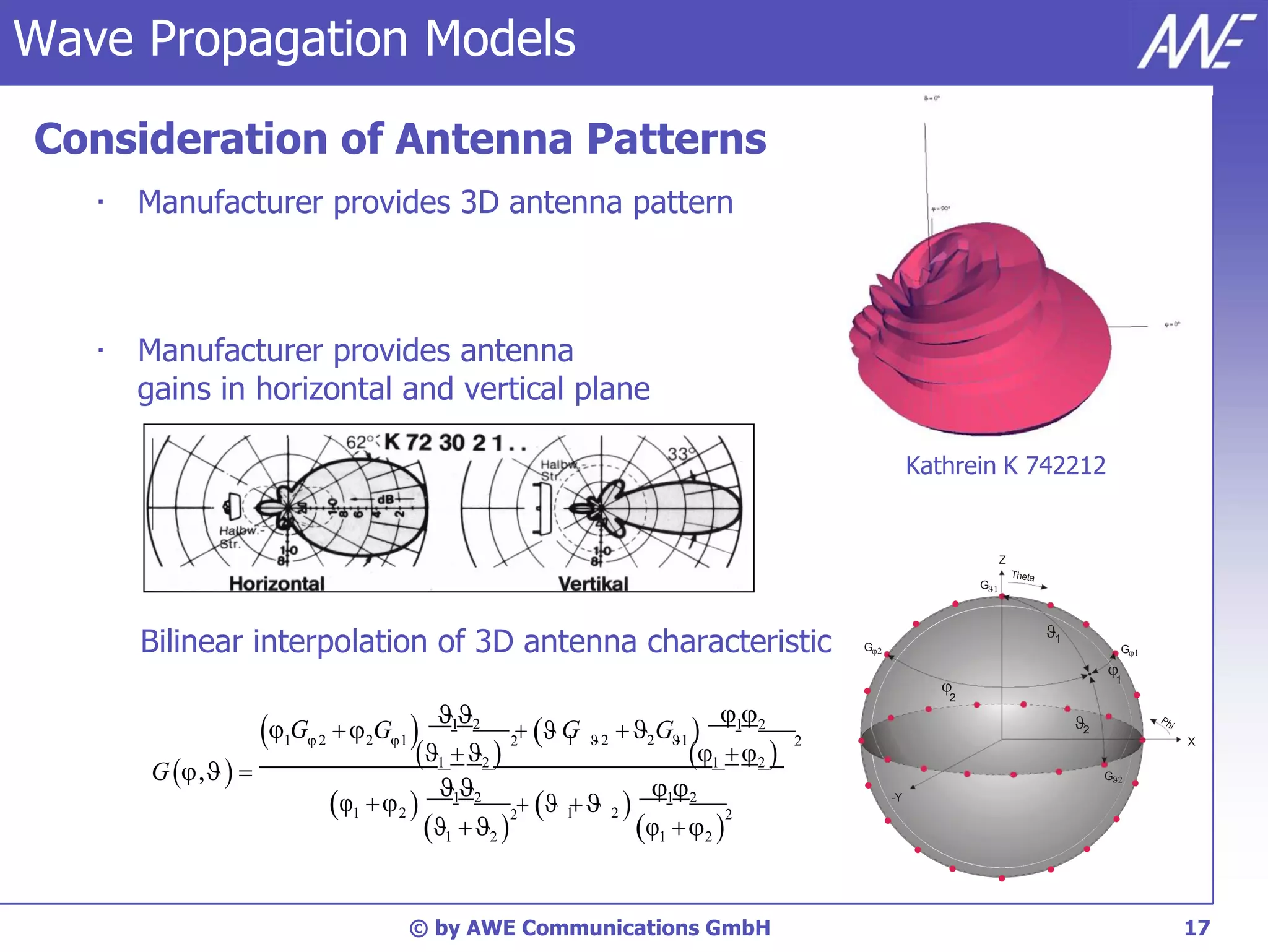

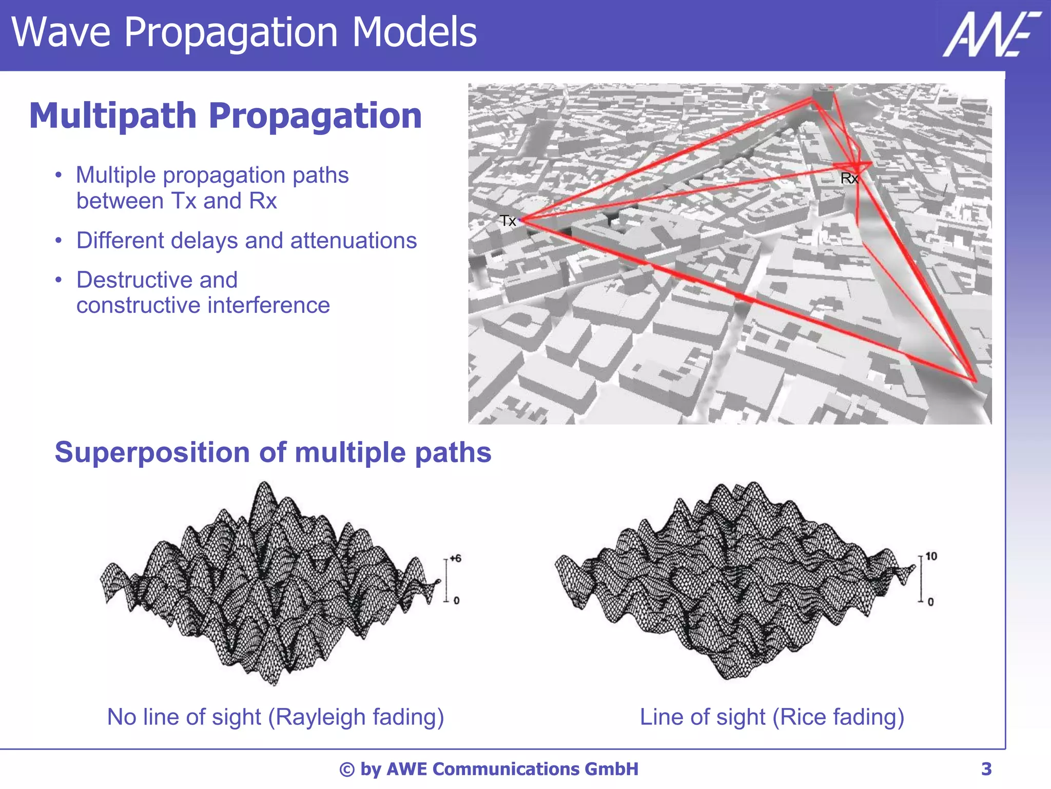
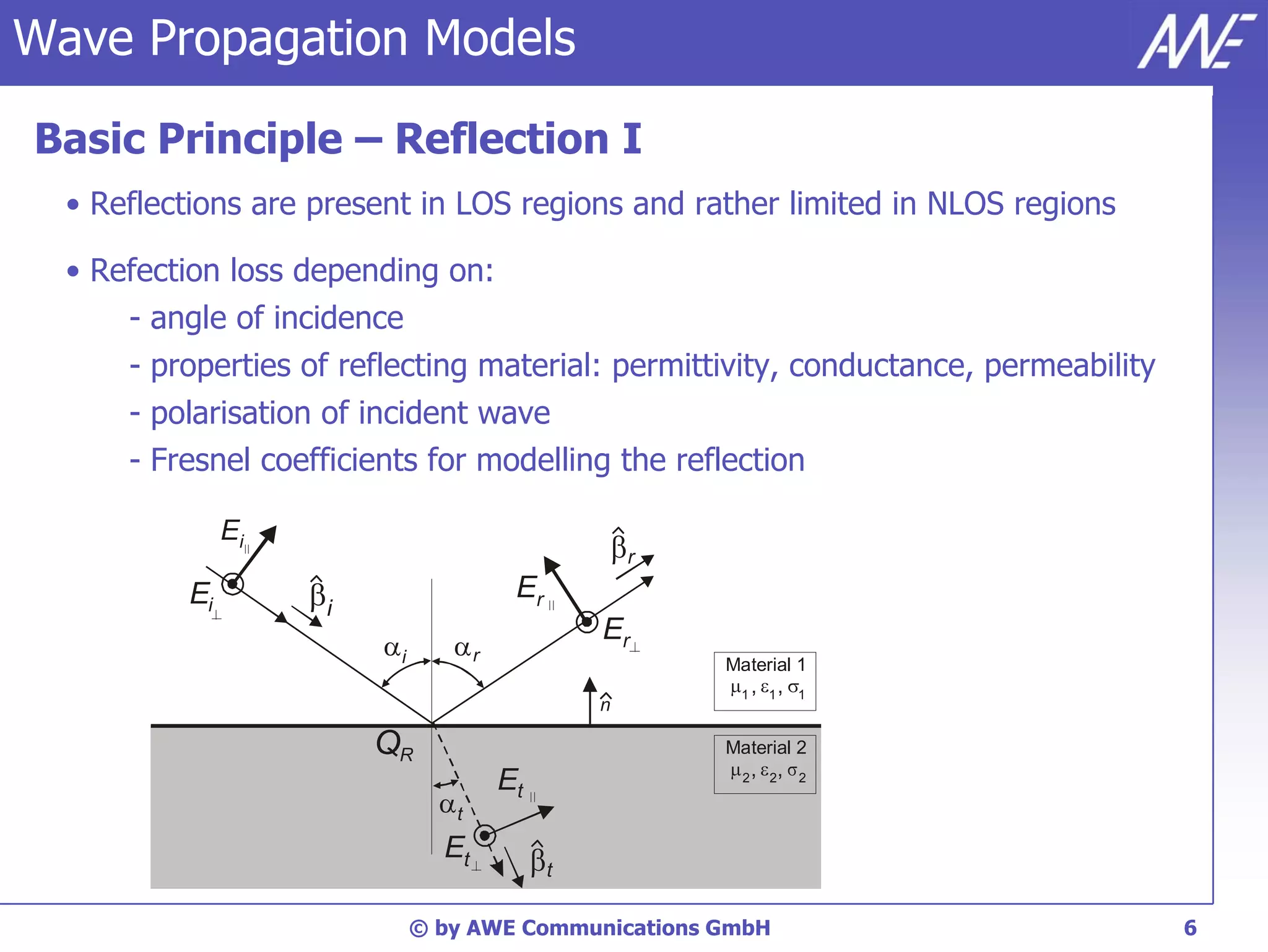
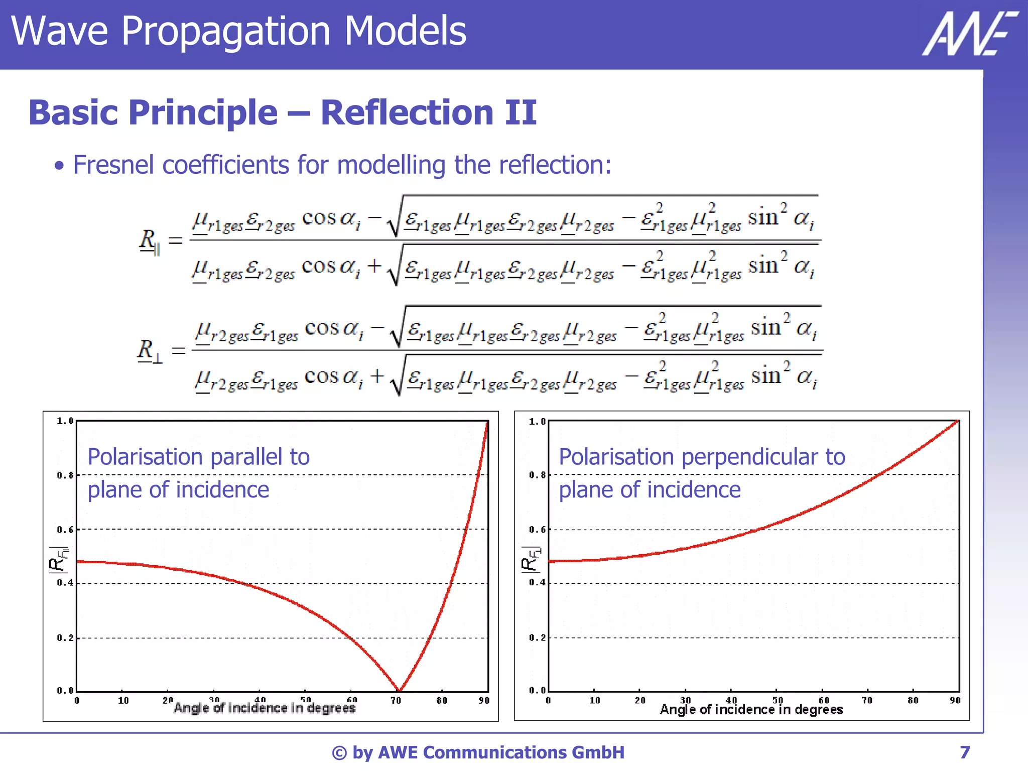
The document discusses principles of wave propagation models. It covers topics like multipath propagation, reflection, diffraction, scattering, and antenna patterns. Multipath propagation results in fading due to multiple signal paths combining constructively and destructively. Reflection, transmission, and diffraction losses are determined by factors like the incident angle and material properties. Scattering occurs on rough surfaces. Antenna patterns are considered using data from manufacturers.