Download to read offline


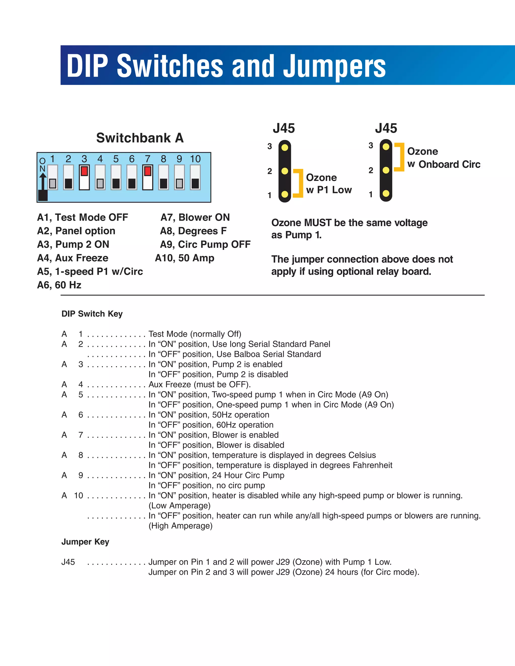


This document provides information about a hot tub control system including its model number, circuit board layout, connections for pumps, lights, blowers, and other components. It also describes dip switch and jumper settings that configure options like temperatures units, pump speeds, and other functions. Wiring diagrams are included for connecting an optional ozone generator at either 120V or 240V.


