Advanced MC/MF Series Motion Control Cards
•
0 likes•173 views

The MC/MF Series mounting cards are designed to host up to three AMC 10A8 servo amplifier modules. The cards provide power and signal connections to the amplifiers and include potentiometers for configuring inputs, outputs, gains and limits. Models beginning with MC host amplifiers only, while MF models also include onboard filters on the motor lines. The document provides details on configuration, tuning and specifications for the mounting cards.

Recommended
More Related Content
What's hot
What's hot (18)
Viewers also liked
Viewers also liked (15)
Similar to Advanced MC/MF Series Motion Control Cards
Similar to Advanced MC/MF Series Motion Control Cards (20)
More from Electromate
More from Electromate (20)
Recently uploaded
Recently uploaded (20)
Advanced MC/MF Series Motion Control Cards
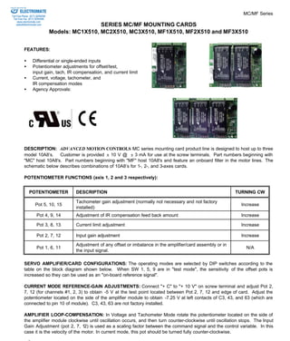
- 1. MC/MF Series SERIES MC/MF MOUNTING CARDS Models: MC1X510, MC2X510, MC3X510, MF1X510, MF2X510 and MF3X510 ELECTROMATE Toll Free Phone (877) SERVO98 Toll Free Fax (877) SERV099 www.electromate.com sales@electromate.com FEATURES: · Differential or single-ended inputs · Potentiometer adjustments for offset/test, input gain, tach, IR compensation, and current limit · Current, voltage, tachometer, and IR compensation modes · Agency Approvals: DESCRIPTION: ADVANCED MOTION CONTROLS MC series mounting card product line is designed to host up to three model 10A8’s. Customer is provided ± 10 V @ ± 3 mA for use at the screw terminals. Part numbers beginning with "MC" host 10A8's. Part numbers beginning with "MF" host 10A8's and feature an onboard filter in the motor lines. The schematic below describes combinations of 10A8’s for 1-, 2-, and 3-axes cards. POTENTIOMETER FUNCTIONS (axis 1, 2 and 3 respectively): POTENTIOMETER DESCRIPTION TURNING CW Pot 5, 10, 15 Tachometer gain adjustment (normally not necessary and not factory installed) Increase Pot 4, 9, 14 Adjustment of IR compensation feed back amount Increase Pot 3, 8, 13 Current limit adjustment Increase Pot 2, 7, 12 Input gain adjustment Increase Pot 1, 6, 11 Adjustment of any offset or imbalance in the amplifier/card assembly or in the input signal. N/A SERVO AMPLIFIER/CARD CONFIGURATIONS: The operating modes are selected by DIP switches according to the table on the block diagram shown below. When SW 1, 5, 9 are in "test mode", the sensitivity of the offset pots is increased so they can be used as an "on-board reference signal". CURRENT MODE REFERENCE-GAIN ADJUSTMENTS: Connect "+ C" to "+ 10 V" on screw terminal and adjust Pot 2, 7, 12 (for channels #1, 2, 3) to obtain -5 V at the test point located between Pot 2, 7, 12 and edge of card. Adjust the potentiometer located on the side of the amplifier module to obtain -7.25 V at left contacts of C3, 43, and 63 (which are connected to pin 10 of module). C3, 43, 63 are not factory installed. AMPLIFIER LOOP-COMPENSATION: In Voltage and Tachometer Mode rotate the potentiometer located on the side of the amplifier module clockwise until oscillation occurs, and then turn counter-clockwise until oscillation stops. The Input Gain Adjustment (pot 2, 7, 12) is used as a scaling factor between the command signal and the control variable. In this case it is the velocity of the motor. In current mode, this pot should be turned fully counter-clockwise. ADVANCED MOTION CONTROLS Sold & Serviced By:
- 2. Sold & Serviced By: ELECTROMATE MC/MF Series Toll Free Phone (877) SERVO98 Toll Free Fax (877) SERV099 www.electromate.com sales@electromate.com IR COMPENSATION CONFIGURATION: Rotate the potentiometer located on the side of the amplifier module clockwise until oscillation occurs, and then turn counter-clockwise until oscillation stops. Repeat this procedure for Pot 4, starting from a fully CW position, turn CCW until oscillation. See section "G" for more information on IR Compensation. ANALOG POSITION LOOP MODE: In this mode the feedback device is an analog potentiometer mechanically tied to the positioned object. This potentiometer can be powered by the card (±10V). The command is an analog signal, which can be supplied by the user, or a potentiometer supplied by the card (±10V). See analog position mode block diagram in section “G”. Tune amplifier in voltage mode (or in IR compensation mode for best results), then connect the analog position feedback and turn Pot 2 clockwise until oscillation occurs. Finally, rotate Pot 2 counter-clockwise to stop oscillation. (Oscillation may not occur). MECHANICAL SPECIFICATIONS: CONNECTORS All versions Screw Terminals A-40 MC1X510 3.80 x 4.98 x 1.10 inches 96.5 x 126.5 x 26.5 mm SIZE MC2X510 6.02 x 4.98 x 1.10 inches 152.9 x 126.5 x 26.5 mm MC3X510 8.00 x 4.98 x 1.10 inches 203.3 x 126.5 x 26.5 mm MC1X510 4 oz. 0.113 kg. WEIGHT MC2X510 5 oz. 0.142 kg. MC3X510 7 oz. 0.198 kg. PIN FUNCTIONS: CONNECTOR PIN NAME DESCRIPTION/NOTES I/O 1 +HV DC power supply (20-80VDC) I 2 GND Power supply ground GND 3 gnd Signal ground (same as P2-2) GND 4 +10V @ 3 mA For Customer Use O P2 5 -10V @ 3 mA For Customer Use O CONNECTOR PIN NAME DESCRIPTION/NOTES I/O 1 -M1, -M2, -M3 - Motor O 2 +M1, +M2, +M3 + Motor O 3 -T1, -T2, -T3 - Tachometer (or analog position feedback) I 4 +T1, +T2, +T3 + Tachometer (or analog position feedback) I 5 +C1, +C2, +C3 + Command signal I 6 -C1, -C2, -C3 - Command signal I 7 INH1,2, 3 Apply +3V to +15V @ 3 mA to inhibit I P3,P4,P5 8 gnd Ground reference GND MOUNTING DIMENSIONS: See page F-6.
- 3. MC/MF Series A-41 Sold & Serviced By: ELECTROMATE Toll Free Phone (877) SERVO98 Toll Free Fax (877) SERV099 www.electromate.com sales@electromate.com
- 4. Sold & Serviced By: ELECTROMATE MC/MF Series Toll Free Phone (877) SERVO98 Toll Free Fax (877) SERV099 www.electromate.com sales@electromate.com A-42
- 5. Sold & Serviced By: ELECTROMATE Toll Free Phone (877) SERVO98 Toll Free Fax (877) SERV099 www.electromate.com sales@electromate.com