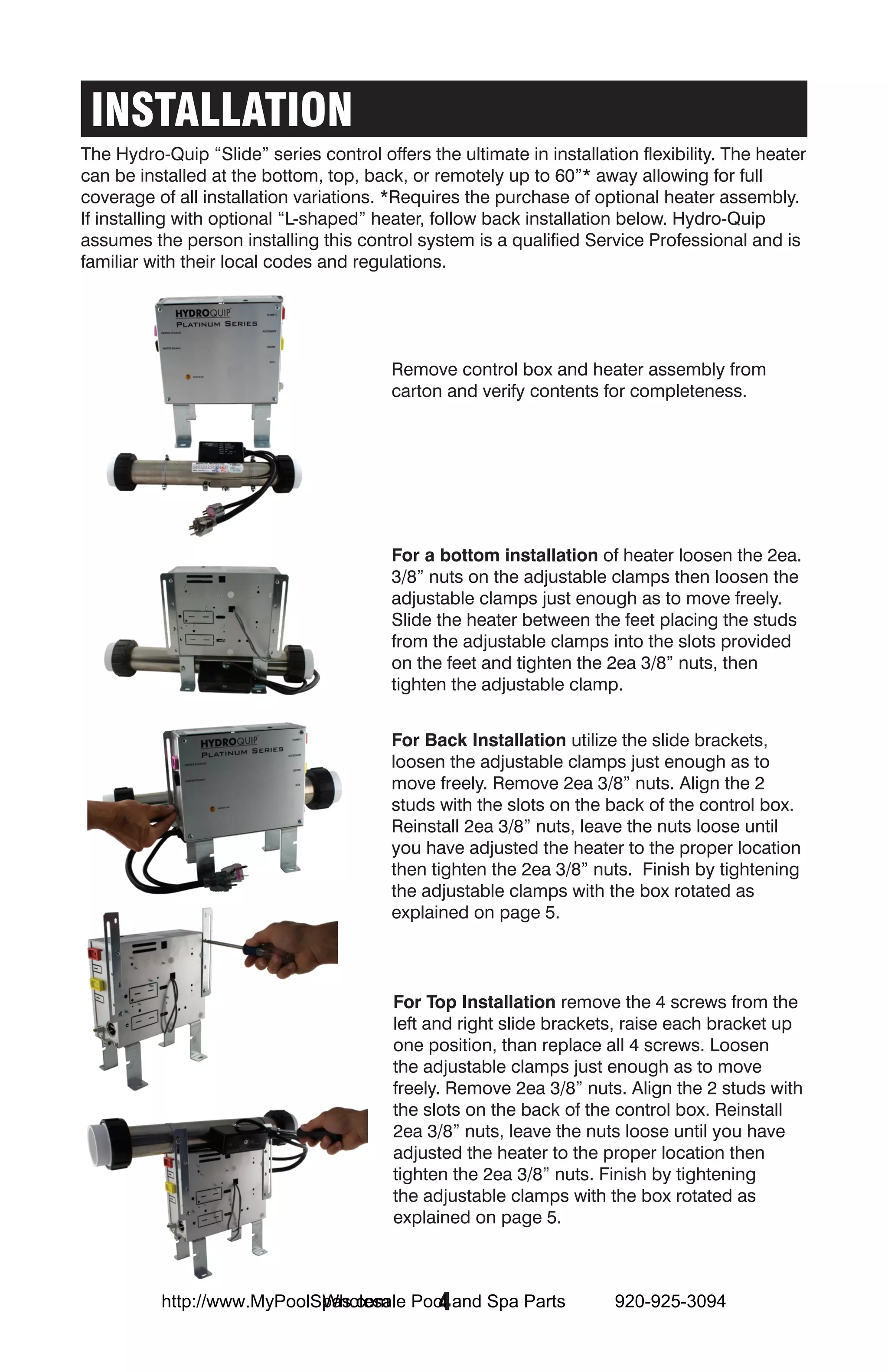
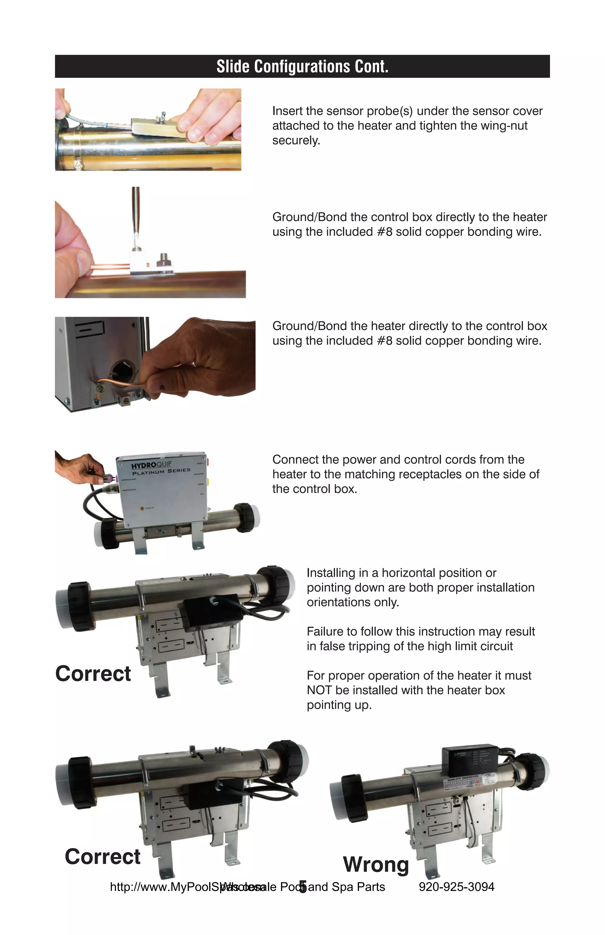
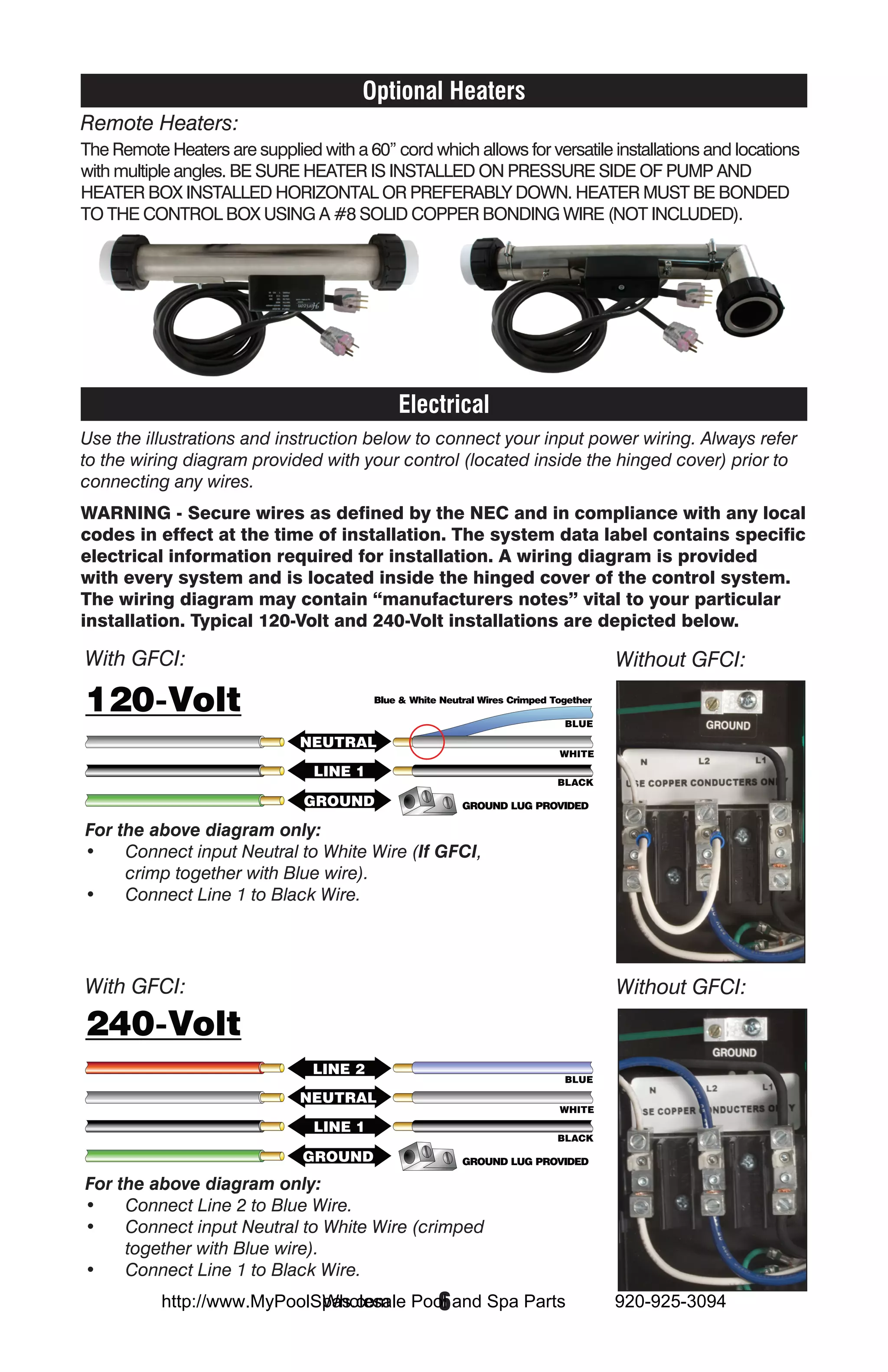
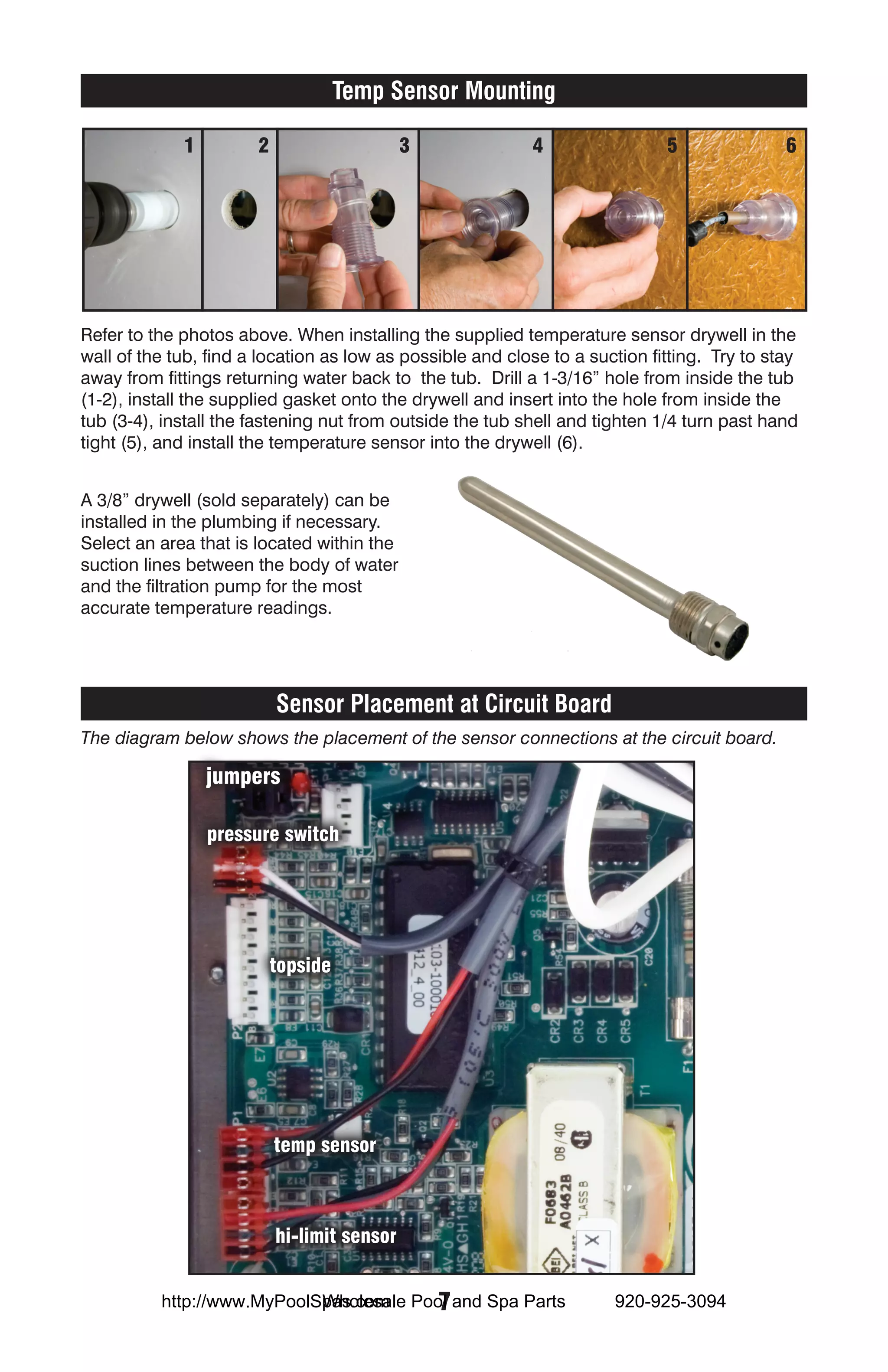
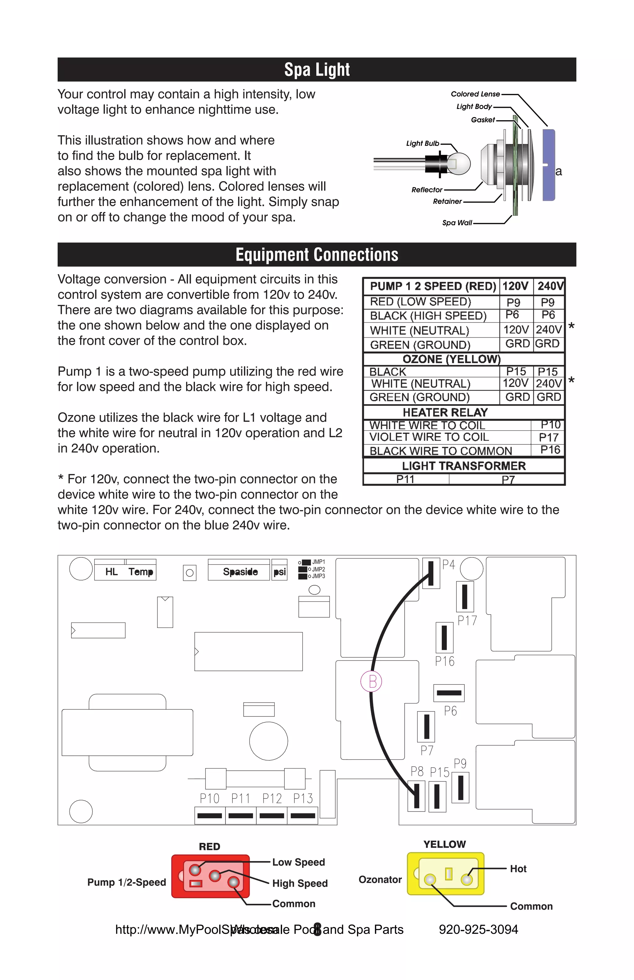
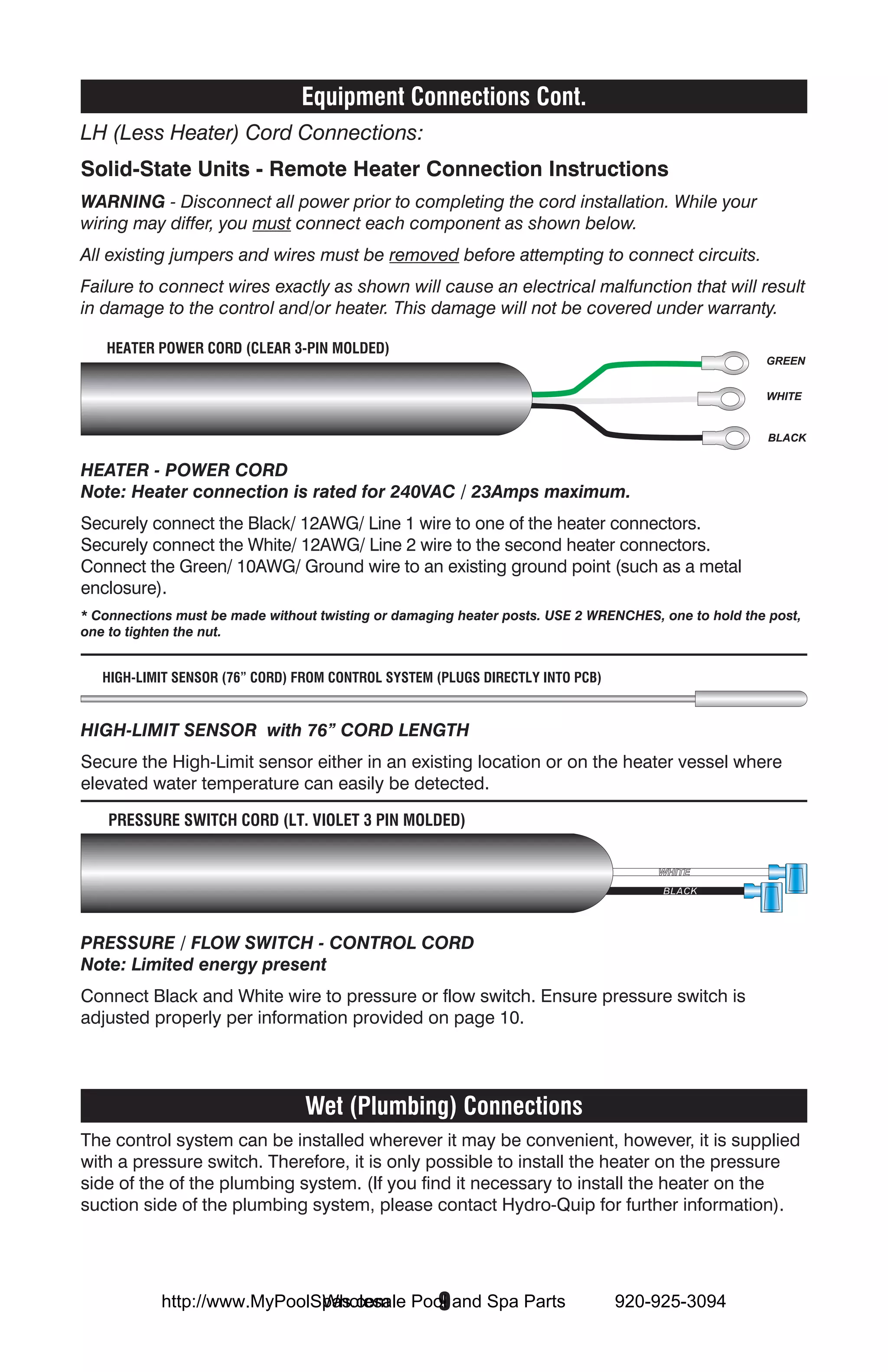
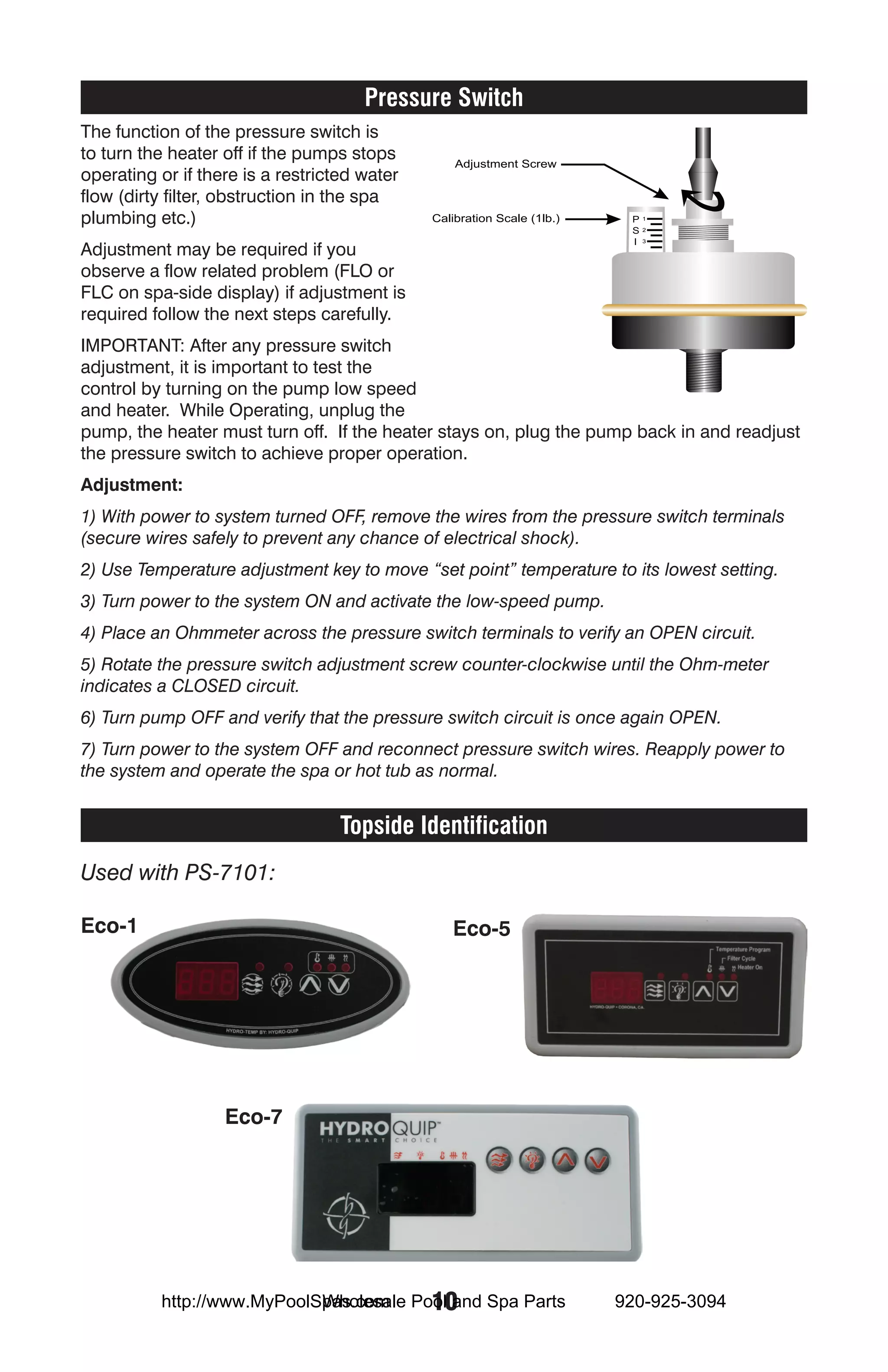
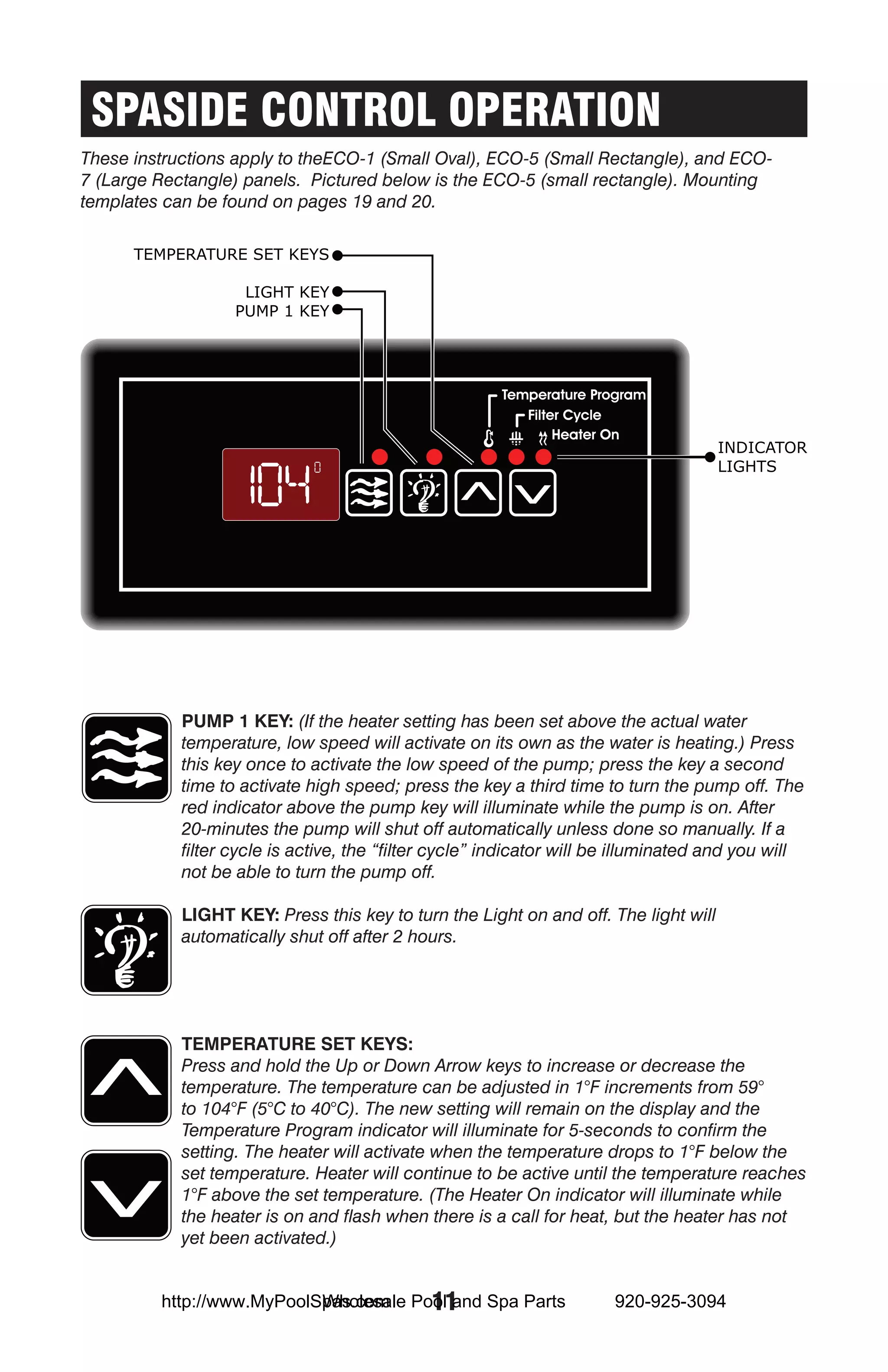
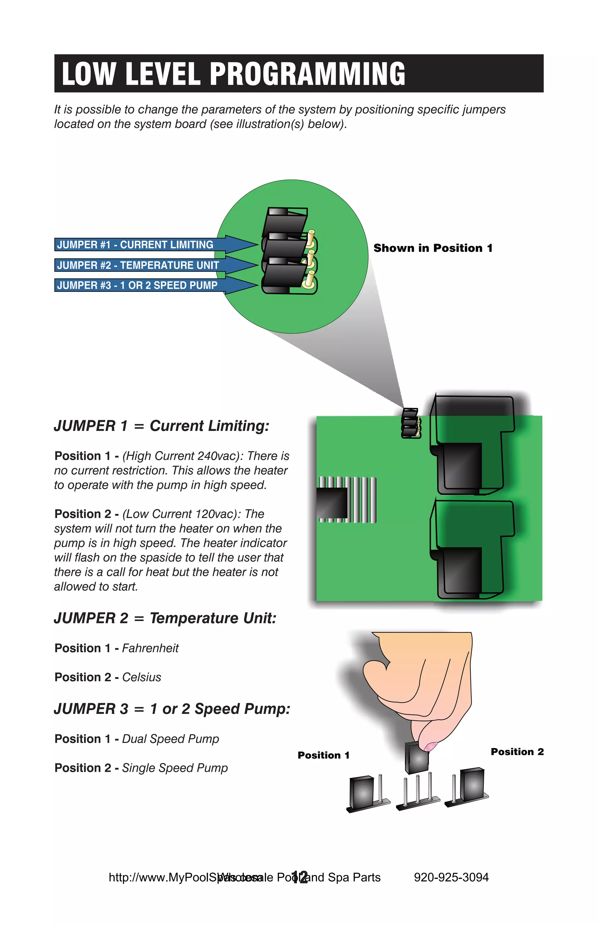
The document provides installation and operation instructions for a Platinum Series pool and spa control system. It includes details on installing remote heaters, electrical connections, temperature sensors, equipment connections, and programming filtration settings. Safety instructions are provided at the beginning regarding proper installation and use of the system.
Arnaud DELOBEL, R&D Director, Quality Assistance
Webinar held on 2nd April 2019.
Hydrogen-Deuterium Exchange Mass Spectrometry (HDX-MS) is a powerful technique for the advanced structural characterisation of proteins and the study of protein-protein interactions.This technique has been used for several decades, mostly in academic labs. Thanks to advances in automation, liquid chromatography and mass spectrometry technologies, this technique can now be used to get reproducible and reliable results in characterisation studies of biotherapeutics. It is complementary to other structural biology techniques such as NMR and X-ray cristallography. Its main advantage is to work in nearly physiological conditions and to require relatively limited amounts of sample.
Access this 45 minutes webinar to learn how HDX-MS can be applied throughout the development of your product to get structural information that can hardly be obtained with other techniques. After a detailed description of the technique and its applications, case studies will be presented in the context of comparability and epitope mapping studies.
Visit www.quality-assistance.com for more information.
ported to slideshow by Corvoxpoolandspapparts.com your rare pool and spa parts super store! all trademarks are trademarks of the rightful owners. We only want to help our clients to have a backup of their pool manuals!
Intex krystalClear Pool Pump manual model 603 for Intex and Bestway swimming ...Shane
Intex krystalClear Pool Pump manual model 603 for Intex and Bestway swimming pools, Operating Manual will teach you all that there is to know about this Intex pool Pump.
Krystal Clear Model 637R filter Pump Manual for Intex and bestway swimming poolsShane
Manual for your Krystal Clear Pool pump model 637R, will work with bestway swimming pools look for our conversion manuals.ported to slideshow by Corvoxpoolandspapparts.com your rare pool and spa parts super store! all trademarks are trademarks of the rightful owners. We only want to help our clients to have a backup of their pool manuals!
CrystalClear Pool Pump 637R manual, Intex KrystalClear pool filter pump manual.ported to slideshow by Corvoxpoolandspapparts.com your rare pool and spa parts super store! all trademarks are trademarks of the rightful owners. We only want to help our clients to have a backup of their pool manuals!
STANLEY FATMAX J7 CS Jump Starter User ManualTim Miller
This is the user manual of the STANLEY FATMAX J7 CS Jump Starter.
>> READ MORE: https://www.obdadvisor.com/jump-starter-with-air-compressor/
Here is a detailed review of the jump starter based on my own experience, including:
- Compatibility
- Features and Functions
- Pros and Cons
Check it out to get the REVIEW and some NOTES about using the tool.
Included with your new spa is a safety sign. The sign is for you and your guest’s protection and is suitable for outdoor use in wet locations. The sign should be placed in a location visible to all users of the spa.
Flooding caused by failed water heaters, washing machines, frozen leaking pipes and leaking plumbing can be a disaster.
Small leaks can create a flooded basement and home if they go undetected.
HERE IS YOUR SOLUTION!
Introducing the ValveSentry™ - the first and only automatic water shut off device that you install yourself - no plumbing required!
The ValveSentry™ device's water sensor can be placed anywhere in your home to detect unwanted water and promptly turns off water at its source.
The ValveSentry™ device fits over almost any ball or gate valve and shuts off your water main when a leak is detected.
Installation of the ValveSentry™ device is simple and doesn't require cutting into plumbing -- anyone can do it with ordinary hand tools.
If you can turn off your water main valve by hand, you can easily install a ValveSentry™ device over it for automatic shut off.
Place a ValveSentry™ water sensor near water heaters, washing machines, sinks, toilets, and plumbing. If a leak occurs, the sensor sends a signal to the controller, which shuts off the water at its source. Installation is simple. . . Operation is automatic.
Leaks do not give you any warning signs!
Hot water heaters, washing machine hoses, toilet and sink valves and hoses - these all can fail suddenly and leak continuously until you come home and discover a flooded house and $1000's of damage.
Don't let a leak cause a flooded home!
Continuously monitor your plumbing and shut off your water at the earliest sign of a leak.
For peace of mind when away at work or on vacation.
Protect your valuable property and treasured memories.
ValveSentry™ Automatic Water Shut Off Valve Features
Easy To Install in 15-30 minutes!
No plumbing required!
Every home needs one!
Add up to 8 water sensors! The kit includes 1 water sensor, add more as desired.
Powerful electrical motor with battery back-up in case of power failure!
Cara Pasang Ariston Water Heater electric 082122541663 atau pemanas air listrik merupakan alat pemanas air yang menggunakan energi listrik sebagai sumber energinya untuk dapat memenuhi kebutuhan mandi air panas keluarga Anda secara praktis. Sebenarnya, untuk pemasangan alat ini bisa dilakukan sendiri tanpa harus memakai jasa tukang. Dengan begitu kita dapat lebih menghemat biaya pengeluaran untuk membayar jasa tukang untuk memasang water heater listrik.
Berikut ini hal yang perlu diperhatikan untuk memasang water heater atau pemanas air listrik :
· Sebelum memasang pemanas air, Anda perlu menyiapkan instalasi pipa untuk jalur air panas dan jalur air dingin yang masuk ke dalam water heater. Pipa yang digunakan untuk saluran air panas pada pemanas air tentunya harus pipa khusus yang tahan terhadap panas tinggi seperti pipa dengan material polypropylene, serta material non-korosif yang tahan terhadap berbagai cairan kimia dan bebas dari sedimentasi (pengikisan).
· Kran mixing atau yang biasa kita kenal dengan kran panas dingin yang memiliki 2 saluran yaitu saluran air panas dan saluran air dingin yang nantinya akan digunakan untuk menyalurkan air dari water heater.
· Alat water heater listrik lebih baik dipasang minimal 1.5m dari lantai agar memudahkan Anda dalam pemasangan dan pengaturan pada water heater serta agar terhindar dari cipratan air mandi.
Cart-Away dry material concrete loaders are used to fill concrete mixing trailers. This manual is specifically for systems that use a touchscreen operating system to control the functions.
This batching system can load u cart, shortstop, concrete titan and other types of mixing trailers. The plan can also be used to load small ready mixed concrete trucks.
Service Solahart 02199316735 Center solahart Pemanas Air Solar Water Heater Tenaga Matahari Kami Dari CV.DAVITAMA Menyediakan Jasa Perbaiakan Pemanas Air SOLAHART
Apakah mesin pemanas air anda bermasalah
1.TIDAK PANAS 2.BOCOR 3.BONGKAR PASANG
5.PENGGANTIAN SPAREPART 6.INSTALASI PIPA AIR PANAS 7.PENJUALAN UNIT
Dengan tenaga ahli kami yang berpengalaman secara profesional dapat kami tangani masalah mesin pemanas air.
Dengan pemanas air tenaga Matahari rutin diservice, maka akan mendapatkan 95% kebutuhan energy secara gratis dari Matahari.
KEUNTUNGAN EKONOMIS DARI PEMANAS AIR TENAGA MATAHARI
Pemanas Air memerlukan energi. Apakah energi tersebut harus dibeli atau tidak, tergantung apakah anda mempunyai Pemanas Air Tenaga Surya. Dengan Pemanas Air Tenaga Surya Solahart, anda dapat mengharapkan mendapat energi matahari yang bebas biaya sampai 95% dari total energi yang diperlukan. Prosentase ini tergantung pada kondisi iklim dan type Pemanas Air Tenaga Surya yang anda pakai.
CV. DAVINATAMA SERVICE
E-mail: davinatama@yahoo.com Nomer Telpon: +6221 99316735 Fax : +6221 48702925
CÔNG TY CỔ PHẦN HẠO PHƯƠNG
Trụ sở chính:
Địa chỉ: Số 88 đường Vĩnh Phú 40, Kp. Hòa Long, P. Vĩnh Phú, Thuận An, Bình Dương.
Văn phòng Hà Nội:
Địa chỉ: Số 95 TT4 – KĐT Mỹ Đình Sông Đà – Phường Mỹ Đình – Q. Nam Từ Liêm – Hà Nội
Chi nhánh Cambodia:
Địa chỉ: The Park Land SenSok, Borey Chip Mong, House Number 22, P11.Sangkat Phnom Penh Thmey, Khan San Sok, Phnom Penh.
Email: cs@haophuong.com – Website: haophuong.com
Facebook: https://www.facebook.com/haophuongcompany/
HOTLINE: 1800 6547
4. IMPORTANT SAFETY INSTRUCTIONS
READ AND FOLLOW ALL INSTRUCTIONS
DANGER To reduce the risk of injury, do not permit children to use this product unless
they are closely supervised at all times.
WARNING - RISK OF CHILD DROWNING. Extreme caution must be exercised to prevent
unauthorized access by children. To avoid accents, ensure that children cannot use a
spa or hot tub unless they are supervised at all times.
DANGER To reduce the risk of injury to persons, do not remove suction fitting covers.
Spa location must accommodate sufficient drainage of water around the base of the
structure, as well as the power source compartment.
Prolonged immersion in water that is warmer than normal body temperature can result
in a dangerous condition known as HYPERTHERMIA. The causes, symptoms, and
effects of hyperthermia may be described as follows: several degrees above the
normal body temperature of 98.6˚F. The symptoms of hyperthermia include dizziness,
fainting, drowsiness, lethargy, and an increase in the internal temperature of the body.
The effects of hyperthermia include (1) unawareness of impending hazard, (2) failure
to perceive heat, (3) failure to recognize the need to exit spa, (4) physical inability
to exit spa, (5) fetal damage in pregnant women, (6) unconsciousness resulting in
danger of drowning. WARNING The use of alcohol, drugs or medication can greatly
increase the risk of fatal hyperthermia in hot tubs and spas.
DANGER - RISK OF ELECTRICAL SHOCK. Install at least 5 feet (1.5m) from all metal
surfaces. (A spa may be installed within 5 feet of metal surfaces if each metal surface
is permanently connected by a solid copper conductor attached to the ground bar
on the terminal box that is provided for this purpose. Refer to NEC and local codes in
effect at the time of installation.)
A ground or bonding bar is provided on the control box to permit connection of a solid
copper bonding conductor between this point and any equipment, metal enclosures
of electrical equipment, metal water pipe, or conduit within 5 feet (1.5m) of the unit as
needed to comply with local requirements.
Bond accessible metal to the dedicated connector on the equipment grounding bus,
bond the equipment ground bus to the local common bonding grid as part of the
installation in the form of (1) a reinforced concrete slab for support, (2) a ground plate
provided beneath the hot tub or spa, or (3) a permanent ground connection that is
acceptable to the local inspection authority.
DANGER RISK OF ELECTRICAL SHOCK. Do not permit any electrical appliance such as
a light, telephone, radio, or television, within 5 feet (1.5m) of a spa or hot tub.
To reduce the risk of injury:
The water in a spa or hot tub should never exceed 104˚F (40˚C). Water temperatures
between 100˚F (38˚C) and 104˚F (40˚C) are considered safe for a healthy adult.
Lower water temperatures are recommended for extended use (exceeding 10-15
minutes) and for young children.
Excessive water temperatures have a high potential for causing fetal damage during the
early months of pregnancy. Pregnant or possibly pregnant women should limit spa
or hot tub water temperatures to 100˚F (38˚C).
Wholesale 2
http://www.MyPoolSpas.com Pool and Spa Parts 920-925-3094
5. Before entering the spa or hot tub, the user should measure the water temperature with an
accurate thermometer.
The use of alcohol, drugs, or medication before or during spa or hot tub use may lead to
unconsciousness with the possibility of drowning.
Persons suffering from obesity or with a medical history of heart disease, low or high blood
pressure, circulatory system problems, or diabetes should consult a physician before
using a spa or hot tub.
Persons using medication should consult a physician before using a spa or hot tub since
some medication may affect heart rate, blood pressure, and circulation.
For Units with a GFCI (Ground Fault Circuit Interrupter)
This appliance is provided with a ground-fault-circuit-interrupter located on the control box.
Before each use and with the unit operating, push the test button. The unit should
stop operating and the reset button should appear. Push the reset button. The unit
should now operate normally. If the interrupter does not perform in this manner, a
ground current is flowing indicating the possibility of electrical shock. Disconnect the
power, or unplug from receptacle, until the fault has been identified and corrected.
For Cord and Plug Connected Units
Connect to a grounded, grounding type receptacle only. NEVER connect the spa to an
extension cord.
Do not bury the cord.
WARNING To reduce the risk of electrical shock, replace damaged cord immediately.
For Permanently Installed Units
A terminal marked “G” or “ground” is provided in the wiring box located inside the
equipment compartment. To reduce the risk of electric shock, connect the terminal
or connector to the grounding terminal of your electrical service or supply panel with
a continuous green insulated copper wire in accordance with National Electric Code
Table 250-95 and any other local codes in effect at the time of installation.
For Permanently Installed Units not Provided with an Internal
Disconnecting Method
The electrical supply for this product must include a suitably rated switch or circuit breaker
to open all ungrounded supply conductors to comply with Section 422-30 of the
National Electric Code, ANSI/NFPA 70 1978. The disconnecting means must be
readily accessible to the tub occupant but installed at least 5 feet (1.5m) from the tub
water.
For Units with Gas Heaters
WARNING - Do not install indoors. This unit uses a gas heater that requires proper
ventilation and is intended for outdoor use only.
For UL Listed Equipment Assemblies
Install at least 5 feet (1.5m) from tub water using nonmetallic plumbing. Install blower
no less than 1 foot (305mm) above the maximum water level to prevent water
from contacting electrical equipment. Install in accordance with blower installation
instructions.
To reduce the risk of drowning from hair and body entrapment, install a suction fitting(s) &
cover(s) with a marked flow rate in gallons-per-minute that equals or exceeds the flow
rate marked on the equipment assembly.
Wholesale 3
http://www.MyPoolSpas.com Pool and Spa Parts 920-925-3094
6. INSTALLATION
The Hydro-Quip “Slide” series control offers the ultimate in installation flexibility. The heater
can be installed at the bottom, top, back, or remotely up to 60”* away allowing for full
coverage of all installation variations. *Requires the purchase of optional heater assembly.
If installing with optional “L-shaped” heater, follow back installation below. Hydro-Quip
assumes the person installing this control system is a qualified Service Professional and is
familiar with their local codes and regulations. Slide Configurations
Remove control box and heater assembly from
carton and verify contents for completeness.
For a bottom installation of heater loosen the 2ea.
3/8” nuts on the adjustable clamps then loosen the
adjustable clamps just enough as to move freely.
Slide the heater between the feet placing the studs
from the adjustable clamps into the slots provided
on the feet and tighten the 2ea 3/8” nuts, then
tighten the adjustable clamp.
For Back Installation utilize the slide brackets,
loosen the adjustable clamps just enough as to
move freely. Remove 2ea 3/8” nuts. Align the 2
studs with the slots on the back of the control box.
Reinstall 2ea 3/8” nuts, leave the nuts loose until
you have adjusted the heater to the proper location
then tighten the 2ea 3/8” nuts. Finish by tightening
the adjustable clamps with the box rotated as
explained on page 5.
For Top Installation remove the 4 screws from the
left and right slide brackets, raise each bracket up
one position, than replace all 4 screws. Loosen
the adjustable clamps just enough as to move
freely. Remove 2ea 3/8” nuts. Align the 2 studs with
the slots on the back of the control box. Reinstall
2ea 3/8” nuts, leave the nuts loose until you have
adjusted the heater to the proper location then
tighten the 2ea 3/8” nuts. Finish by tightening
the adjustable clamps with the box rotated as
explained on page 5.
Wholesale 4
http://www.MyPoolSpas.com Pool and Spa Parts 920-925-3094
7. Slide Configurations Cont.
Insert the sensor probe(s) under the sensor cover
attached to the heater and tighten the wing-nut
securely.
Ground/Bond the control box directly to the heater
using the included #8 solid copper bonding wire.
Ground/Bond the heater directly to the control box
using the included #8 solid copper bonding wire.
Connect the power and control cords from the
heater to the matching receptacles on the side of
the control box.
Installing in a horizontal position or
pointing down are both proper installation
orientations only.
Failure to follow this instruction may result
in false tripping of the high limit circuit
Correct For proper operation of the heater it must
NOT be installed with the heater box
pointing up.
Correct Wrong
Wholesale 5
http://www.MyPoolSpas.com Pool and Spa Parts 920-925-3094
8. Optional Heaters
Remote Heaters:
The Remote Heaters are supplied with a 60” cord which allows for versatile installations and locations
with multiple angles. BE SURE HEATER IS INSTALLED ON PRESSURE SIDE OF PUMP AND
HEATER BOX INSTALLED HORIZONTAL OR PREFERABLY DOWN. HEATER MUST BE BONDED
TO THE CONTROL BOX USING A #8 SOLID COPPER BONDING WIRE (NOT INCLUDED).
Electrical
Use the illustrations and instruction below to connect your input power wiring. Always refer
to the wiring diagram provided with your control (located inside the hinged cover) prior to
connecting any wires.
WARNING - Secure wires as defined by the NEC and in compliance with any local
codes in effect at the time of installation. The system data label contains specific
electrical information required for installation. A wiring diagram is provided
with every system and is located inside the hinged cover of the control system.
The wiring diagram may contain “manufacturers notes” vital to your particular
installation. Typical 120-Volt and 240-Volt installations are depicted below.
With GFCI: Without GFCI:
For the above diagram only:
• Connect input Neutral to White Wire (If GFCI,
crimp together with Blue wire).
• Connect Line 1 to Black Wire.
With GFCI: Without GFCI:
For the above diagram only:
• Connect Line 2 to Blue Wire.
• Connect input Neutral to White Wire (crimped
together with Blue wire).
• Connect Line 1 to Black Wire.
Wholesale 6
http://www.MyPoolSpas.com Pool and Spa Parts 920-925-3094
9. Temp Sensor Mounting
1 2 3 4 5 6
Refer to the photos above. When installing the supplied temperature sensor drywell in the
wall of the tub, find a location as low as possible and close to a suction fitting. Try to stay
away from fittings returning water back to the tub. Drill a 1-3/16” hole from inside the tub
(1-2), install the supplied gasket onto the drywell and insert into the hole from inside the
tub (3-4), install the fastening nut from outside the tub shell and tighten 1/4 turn past hand
tight (5), and install the temperature sensor into the drywell (6).
A 3/8” drywell (sold separately) can be
installed in the plumbing if necessary.
Select an area that is located within the
suction lines between the body of water
and the filtration pump for the most
accurate temperature readings.
Sensor Placement at Circuit Board
The diagram below shows the placement of the sensor connections at the circuit board.
jumpers
pressure switch
topside
temp sensor
hi-limit sensor
Wholesale 7
http://www.MyPoolSpas.com Pool and Spa Parts 920-925-3094
10. Spa Light
Your control may contain a high intensity, low
voltage light to enhance nighttime use.
This illustration shows how and where
to find the bulb for replacement. It
also shows the mounted spa light with a
replacement (colored) lens. Colored lenses will
further the enhancement of the light. Simply snap
on or off to change the mood of your spa.
Equipment Connections
Voltage conversion - All equipment circuits in this
control system are convertible from 120v to 240v.
There are two diagrams available for this purpose:
the one shown below and the one displayed on *
the front cover of the control box.
Pump 1 is a two-speed pump utilizing the red wire
for low speed and the black wire for high speed. *
Ozone utilizes the black wire for L1 voltage and
the white wire for neutral in 120v operation and L2
in 240v operation.
* For 120v, connect the two-pin connector on the
device white wire to the two-pin connector on the
white 120v wire. For 240v, connect the two-pin connector on the device white wire to the
two-pin connector on the blue 240v wire.
JMP1
JMP2
JMP3
RED YELLOW
Low Speed
Hot
Pump 1/2-Speed High Speed Ozonator
Common Common
Wholesale 8
http://www.MyPoolSpas.com Pool and Spa Parts 920-925-3094
11. Equipment Connections Cont.
LH (Less Heater) Cord Connections:
Solid-State Units - Remote Heater Connection Instructions
WARNING - Disconnect all power prior to completing the cord installation. While your
wiring may differ, you must connect each component as shown below.
All existing jumpers and wires must be removed before attempting to connect circuits.
Failure to connect wires exactly as shown will cause an electrical malfunction that will result
in damage to the control and/or heater. This damage will not be covered under warranty.
HEATER POWER CORD (CLEAR 3-PIN MOLDED)
GREEN
WHITE
BLACK
HEATER - POWER CORD
Note: Heater connection is rated for 240VAC / 23Amps maximum.
Securely connect the Black/ 12AWG/ Line 1 wire to one of the heater connectors.
Securely connect the White/ 12AWG/ Line 2 wire to the second heater connectors.
Connect the Green/ 10AWG/ Ground wire to an existing ground point (such as a metal
enclosure).
* Connections must be made without twisting or damaging heater posts. USE 2 WRENCHES, one to hold the post,
one to tighten the nut.
HIGH-LIMIT SENSOR (76” CORD) FROM CONTROL SYSTEM (PLUGS DIRECTLY INTO PCB)
HIGH-LIMIT SENSOR with 76” CORD LENGTH
Secure the High-Limit sensor either in an existing location or on the heater vessel where
elevated water temperature can easily be detected.
PRESSURE SWITCH CORD (LT. VIOLET 3 PIN MOLDED)
WHITE
BLACK
PRESSURE / FLOW SWITCH - CONTROL CORD
Note: Limited energy present
Connect Black and White wire to pressure or flow switch. Ensure pressure switch is
adjusted properly per information provided on page 10.
Wet (Plumbing) Connections
The control system can be installed wherever it may be convenient, however, it is supplied
with a pressure switch. Therefore, it is only possible to install the heater on the pressure
side of the of the plumbing system. (If you find it necessary to install the heater on the
suction side of the plumbing system, please contact Hydro-Quip for further information).
Wholesale 9
http://www.MyPoolSpas.com Pool and Spa Parts 920-925-3094
12. Pressure Switch
The function of the pressure switch is
to turn the heater off if the pumps stops
operating or if there is a restricted water
flow (dirty filter, obstruction in the spa
plumbing etc.)
Adjustment may be required if you
observe a flow related problem (FLO or
FLC on spa-side display) if adjustment is
required follow the next steps carefully.
IMPORTANT: After any pressure switch
adjustment, it is important to test the
control by turning on the pump low speed
and heater. While Operating, unplug the
pump, the heater must turn off. If the heater stays on, plug the pump back in and readjust
the pressure switch to achieve proper operation.
Adjustment:
1) With power to system turned OFF, remove the wires from the pressure switch terminals
(secure wires safely to prevent any chance of electrical shock).
2) Use Temperature adjustment key to move “set point” temperature to its lowest setting.
3) Turn power to the system ON and activate the low-speed pump.
4) Place an Ohmmeter across the pressure switch terminals to verify an OPEN circuit.
5) Rotate the pressure switch adjustment screw counter-clockwise until the Ohm-meter
indicates a CLOSED circuit.
6) Turn pump OFF and verify that the pressure switch circuit is once again OPEN.
7) Turn power to the system OFF and reconnect pressure switch wires. Reapply power to
the system and operate the spa or hot tub as normal.
Topside Identification
Used with PS-7101:
Eco-1 Eco-5
Eco-7
Wholesale 10
http://www.MyPoolSpas.com Pool and Spa Parts 920-925-3094
13. SPASIDE CONTROL OPERATION
These instructions apply to theECO-1 (Small Oval), ECO-5 (Small Rectangle), and ECO-
7 (Large Rectangle) panels. Pictured below is the ECO-5 (small rectangle). Mounting
templates can be found on pages 19 and 20.
Pump 1 Key: (If the heater setting has been set above the actual water
temperature, low speed will activate on its own as the water is heating.) Press
this key once to activate the low speed of the pump; press the key a second
time to activate high speed; press the key a third time to turn the pump off. The
red indicator above the pump key will illuminate while the pump is on. After
20-minutes the pump will shut off automatically unless done so manually. If a
filter cycle is active, the “filter cycle” indicator will be illuminated and you will
not be able to turn the pump off.
Light Key: Press this key to turn the Light on and off. The light will
automatically shut off after 2 hours.
Temperature set keys:
Press and hold the Up or Down Arrow keys to increase or decrease the
temperature. The temperature can be adjusted in 1°F increments from 59°
to 104°F (5°C to 40°C). The new setting will remain on the display and the
Temperature Program indicator will illuminate for 5-seconds to confirm the
setting. The heater will activate when the temperature drops to 1°F below the
set temperature. Heater will continue to be active until the temperature reaches
1°F above the set temperature. (The Heater On indicator will illuminate while
the heater is on and flash when there is a call for heat, but the heater has not
yet been activated.)
Wholesale 11
http://www.MyPoolSpas.com Pool and Spa Parts 920-925-3094
14. LOW LEVEL PROGRAMMING
It is possible to change the parameters of the system by positioning specific jumpers
located on the system board (see illustration(s) below).
JUMPER 1 = Current Limiting:
Position 1 - (High Current 240vac): There is
no current restriction. This allows the heater
to operate with the pump in high speed.
Position 2 - (Low Current 120vac): The
system will not turn the heater on when the
pump is in high speed. The heater indicator
will flash on the spaside to tell the user that
there is a call for heat but the heater is not
allowed to start.
JUMPER 2 = Temperature Unit:
Position 1 - Fahrenheit
Position 2 - Celsius
JUMPER 3 = 1 or 2 Speed Pump:
Position 1 - Dual Speed Pump
Position 2 - Single Speed Pump
Wholesale 12
http://www.MyPoolSpas.com Pool and Spa Parts 920-925-3094
15. PROGRAMMING FILTRATION
Programming Filter Cycles: Filtration cycles can run once (1) every 24 hours, twice (2)
every 12 hours or three (3) times every 8 hours to keep the water clean & sanitary. Press
and hold the PUMP KEY until the current setting is displayed. Use the TEMPERATURE
SET KEY to increase or decrease the setting. It is recommended to schedule the filtration
cycles so they do not interfere with sleeping hours.
Programming Filter Cycle Duration: The duration of each can be set to 60 (1 hours), 120
(2 hours), 180 (3 hours) or 480 (8 hours). Press and hold the LIGHT KEY until the current
setting is displayed. Use the TEMPERATURE SET KEY to increase or decrease the setting.
Filtration cycles will take effect at the time these settings are changed. If filtration setup is
accomplished at 12:00pm and the cycles are set to two (2) per day, the cycles will activate
at 12:00pm & 12:00am.
Note: If a key is not pressed within 5 seconds during programming, the system will
revert back to the monitoring mode. If the Pump and/or light were turned on during the
programming process, turn them off.
* Note: When filter cycle starts the blower (or pump 2, if equipped) will activate for
1-minute then turn off. The pump will continue to run for the remainder of the filter
cycle.
* Note: If the spa is being used during the filter cycle, the cycle will be suspended for
a period of 40-minutes or until the spa is no longer in use.
OPTIONAL EQUIPMENT
Cord Adapter Kits:
Cord Adapter Kits are available which allow you to quickly replace
a control system without changing the original cords . These
cord adapters allow you to take a 4-pin amp style plug from the
component and quickly convert it to the molded lit mini plug for the
control system, saving you hours of install time.
Wholesale 13
http://www.MyPoolSpas.com Pool and Spa Parts 920-925-3094
16. OPERATIONAL CONSIDERATIONS
The following describes situation you may encounter and situations to be aware of.
Warm Weather Conditions
Since your spa will normally be expected to maintain warm to hot water ready for use, a
great deal of attention has been directed to the energy conservation detail of insulation
so as to keep electrical costs down. Energy conservation efficiency may be achieved by
extensive insulation of the skirt, plumbing and spa shell, and in some climates full foam
insulation may have been provided.
This energy conservation feature may cause an inconvenience during warmer times
of the year. During warm periods of the year, the temperature within the equipment
compartment can elevate to a point that the pump will automatically turn off for a short
period of time (15-30 minutes) to allow the pump to cool down before automatically
restarting. This cool down feature will not harm your spa but serves only to protect the
pump from damage and as an indicator that it is too hot. To minimize this occurrence,
refrain from using your Hydrotherapy Jets for prolonged periods of time during warm
seasons.
The jet pump chosen for your spa has been specifically sized for maximum performance
and your Hydrotherapy enjoyment.
Filtration System
Please refer to your Spa Manufacturer’s owner’s manual regarding the operation,
maintenance, and cleaning of your filtration system.
Dirty or clogged filters can cause a water flow restriction and you may experience difficulty
in reaching and/or maintaining desired heat levels.
Winterizing
When freezing weather and/or power losses are expected, contact your local spa dealer
for freeze protection or winterizing recommendations for both the spa and the equipment
system. Freeze related damage is not covered by the warranty.
Chemical Water Treatment
Your dealer is familiar with local water conditions and which chemicals are compatible with
and designed specifically for your spa. This is the best person to advise you on proper
water quality management.
The one thing you can do to insure years of trouble free equipment operation is to
maintain proper water chemistry.
Two basic goals of the chemical water treatment are sanitizing and balancing the water.
Sanitizing simply means keeping the water free from living microorganisms including
algae, bacteria, and viruses. The current most popular chemicals for sanitizing include
chlorine, bromine, and ozone.
Balancing water means establishing a balance among pH, total alkalinity, and total
hardness. Water that is unbalanced can corrode the spa and it’s support equipment or
leave deposits of minerals. Properly balanced water is essential to allow the sanitizing
chemical to work effectively. There are numerous chemical additives to help you in
controlling pH, total hardness, and total alkalinity. NEVER use softened water when filling
your spa. Softened water is extremely corrosive to metal parts of the spa equipment and
may lead to unforeseen failure.
Sometimes, despite your most diligent efforts, your water may become too far out of
balance to be managed chemically. At this point it is probably better to drain and clean the
spa and start over with fresh water.
Equipment failure caused by improper water chemistry will not be covered under warranty.
Wholesale 14
http://www.MyPoolSpas.com Pool and Spa Parts 920-925-3094
17. TROUBLESHOOTING
The following describes situations and possible solutions to common problems you may
encounter as a spa owner.
Nothing Operates
Main Breaker is OFF – Set to on.
Sub-Panel Breaker is OFF – Set to On.
Power switch is in OFF position – Set to on.
Component(s) are not plugged in – Plug in components.
Power cord is not plugged in – Plug in power cord.
Over-Heat Protection is On – Refer to page 20.
No, Low or Surging Water Flow
Air Lock in Plumbing System – “Bleed” the system
Restricted Flow – Insure that the water shut-off valves are open and that suction fittings are
not blocked by debris.
Dirty Filter – Clean or replace filter.
Low Water Level – Increase water level to recommended level.
No Low Speed Pump Operation
Low Level Programming Incorrect – Contact your local dealer
Over-Temperature protection On – Refer to page 20.
Pump Not Plugged- In – Plug in the pump.
No Jets or Blower Operation
Blower or Pump Not Plugged-In – Plug in the Blower or Pump.
Over-Heat Protection On – Refer to page 20.
No Therapy Jet Operation
Water Shut-off Valves are Closed – Open Shut-off valves.
Dirty Filter – Clean or replace filter.
Jets Not Properly Adjusted – Adjust jets.
Diverter Valve Not Properly Adjusted – Adjust diverter valve.
Thermal Overload Tripping – Check for restricted flow of water.
Over-Heat Protection On – Refer to page 20.
Water Leaks
Spa overfilled – Adjust water level.
Too many people in the Spa – Adjust water level.
Drain-Valve left open – Close drain valve.
Couplings or Unions Loose – Tighten or contact your local dealer.
Pump Seal Leaking – Contact your local dealer.
Plumbing Connections Leaking – Contact your local dealer.
Water Leaking from Spa side Control – Contact your local dealer.
Water in Air Blower Plumbing – Contact your local dealer.
Wholesale 15
http://www.MyPoolSpas.com Pool and Spa Parts 920-925-3094
18. No Heat
Temperature Not Set Correctly – Adjust Set Point.
Over-Heat Protection On – Refer to page 20.
Current limiting On – 120V Systems will not heat if High-speed or Blower is on. Contact
your Local dealer.
No Power – Reset breaker at service panel.
Low Water Flow – Clean or Replace filter.
High Heat
Temperature Sensor Not in Dry-Well – Place sensor in dry-well.
Temperature Set Too High – Adjust Set Point.
High Ambient Temperature – Remove spa cover.
GFCI Trips Occasionally
Lightning or Electrical Storm, Power Surge, Extreme Humid Conditions, or Radio
Frequency Interference – Reset GFCI - Mounted at control box or service panel.
NOTE: GFCI must be properly grounded and bonded.
GFCI Trips Immediately
Defective Component – Contact a qualified service technician for assistance.
If this is a new electrical installation verify that the electrical service is wired as described
below. With the neutral wire, from control box, attached to the neutral terminal on the load
side of the GFCI breaker.
Wholesale 16
http://www.MyPoolSpas.com Pool and Spa Parts 920-925-3094
19. ERROR INDICATION
To assist the user in identifying problems with the spa, the system will display an error
message. These messages will be helpful when communicating with your local dealer or
qualified technician if a problem should arise.
Pressure or Flow Switch Activated – The flow or pressure switch
is sensing water pressure or flow while the pump is not running. To clear
the error, try cycling the pump through low and high speeds. If this error
does not clear when the pump is off......
Contact your local spa dealer
Pressure or Flow switch Not Activated – The flow or pressure
switch is not sensing water pressure or flow while the pump is running. To
clear the error, try cycling the pump through low and high speeds. If this
does not clear the error, the spa filter may be dirty, possibly obstructing
water flow. If, after cleaning the filter, cycling the pump through low and
high speeds does not clear the error....
Contact your local spa dealer
Temperature sensor malfunction – This error will occur when
a problem with the temperature sensor exists. This error may also occur if
the system is activated while the water temperature is below 35°F. The best
thing to do when this error occurs is to....
Contact your local spa dealer
Overheat or High-Limit Protection – There are three (3) stages of
over heat:
1 – The spa water has exceeded 112°F. The heater, pump and accessory
will be deactivated until the water cools to 109°F. Be sure to check the
actual temperature with an accurate thermometer.
2 – The spa water has exceeded 119°F. The heater will deactivate while
the pump and accessory will still operate. The air blower (if equipped) can
be activated to help cool the water. WATER MUST BE BELOW 119°F AND
POWER MUST BE RESET TO CLEAR THE “HL ERROR ”
A dirty spa filter can also cause restricted flow of water, so be sure the filter
is cleaned regularly and ensure that all water shutoff valves are open.
If the system has been operating normally until now, the pump may be
overheating the spa. Refer to “Programming Filtration” on Page 15 and
reduce the duration and/or number of cycles per day.
3 – If you’ve eliminated items 1&2 as problems, the high limit sensor may
have malfunctioned If this is the case, ...
Contact your local spa dealer
Wholesale 17
http://www.MyPoolSpas.com Pool and Spa Parts 920-925-3094
20. Error Indication Cont.
Freeze Protection – This is indicated by the filter light flashing on the topside. There
are two (2) levels of freeze protection integrated into the system.
1 – SMART WINTER MODE, this mode will activate anytime the water temperature falls
below 59°F. This mode will be active for a period of 24 hours. In this mode, if a pump has
not been activated in the last 2 hours, the system will automatically turn it on for one (1)
minute to prevent freezing. The “Filter Cycle” indicator will illuminate while the mode is
active.
2 – If the spa water temperature drops below 49°F, the heater & pump will be activated until
the water temperature reaches 50°F. While freeze protection is active no other functions
will be possible.
SYSTEM DATA LABEL
The system data label is located on the control box. This label is very important and
contains information you will need to establish your electrical service. The voltage and
amperage ratings are shown on the bottom of the label. Product, Model, Serial and Code
numbers are also shown on the label.
Note: This information will be necessary if you should ever have to request warranty or any
other type of service.
PS-710x
HOR03-xxxx-
120 240
16 40/48
HQ-6000
1 PHASE - 60Hz
Refer to NEC for Breaker Sizing
Wholesale 18
http://www.MyPoolSpas.com Pool and Spa Parts 920-925-3094
21. WARRANTY INFORMATION
To all original purchasers, HydroQuip, warrants this product to be free from defects in
material and workmanship for a period of 3 years from the date of purchase.
Hydro-Quip will, at it’s discretion, repair or replace any part which has been found to be
defective.
This warranty excludes damage as a result of: normal wear, freezing, low voltage, chemical
abuse, accident, negligence, alteration, improper installation, use or care.
To obtain warranty service, return defective products within the warranty period to Hydro-
Quip.
The Hydro-Quip Limited Warranty is for service on the control box only. Purchaser is
responsible for removal or reinstallation labor, freight charges, or any other such costs
incurred in obtaining warranty service.
Hydro-Quip assumes no responsibility for incidental or consequential damages. Some
states do not allow the exclusion of incidental or consequential damages, so the above
limitations and exclusions may not apply to you. This warranty gives you specific legal
rights and you may also have other rights, which vary from state to state.
If you are the end user for this control system, the spa dealer may provide a different
warranty; contact your spa dealer for details and warranty information.
Wholesale 19
http://www.MyPoolSpas.com Pool and Spa Parts 920-925-3094
22. TOPSIDE MOUNTING
IMPORTANT - The template on this page is to be used with ECO-1, 2, 5 & 6 series
controls ONLY.
2 5/8”
(2ea) 1” Holes
Wholesale 20
http://www.MyPoolSpas.com Pool and Spa Parts 920-925-3094