Download to read offline

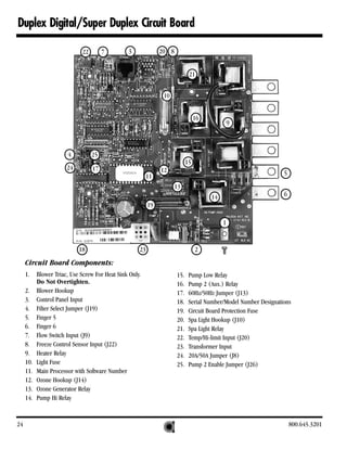
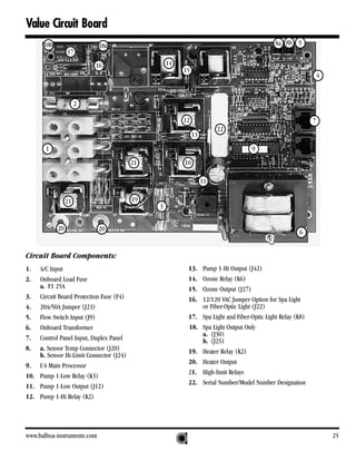
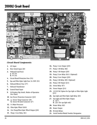


This document is a technical service manual from Balboa Instruments that provides guidance on servicing Balboa control systems for spas. It includes sections on safety, required tools and components, system descriptions, troubleshooting wiring and voltage issues, testing circuit boards, changing circuit boards, filter settings, optional features, and information on specific Balboa circuit board models. The manual aims to help qualified technicians safely service Balboa control systems.