Download to read offline
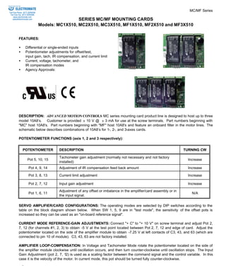


The MC/MF Series mounting cards are designed to host up to three AMC 10A8 servo amplifier modules. The cards provide power and signal connections to the amplifiers and include potentiometers for configuring inputs, outputs, gains and limits. Models beginning with MC host amplifiers only, while MF models also include onboard filters on the motor lines. The document provides details on configuration, tuning and specifications for the mounting card series.