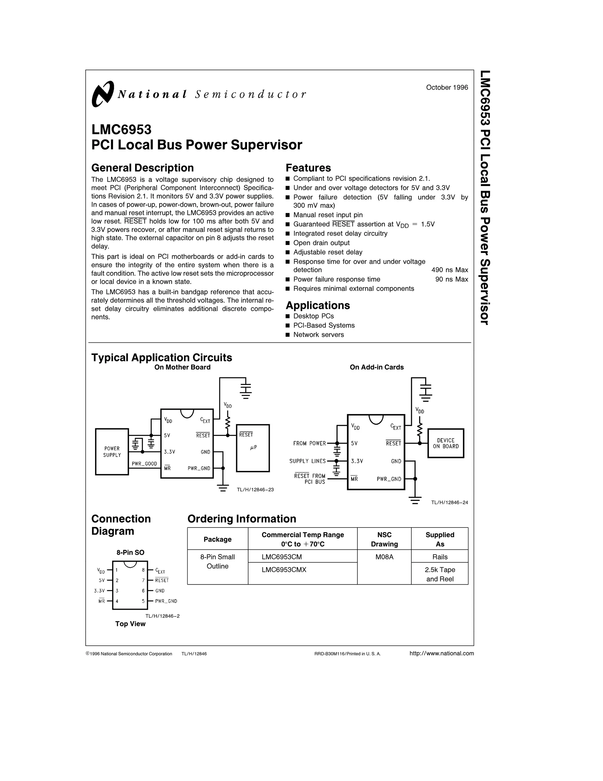
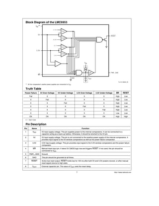
The LMC6953 is a voltage supervisor chip designed to meet PCI specifications. It monitors the 5V and 3.3V power supplies for out of range voltages, power failures, and manual resets. When any fault is detected, it asserts an active low reset (RESET) signal for 100ms to reset associated devices. It has built-in voltage reference and reset delay circuitry requiring minimal external components.
ABB Power Products - Medium & High Voltage Transformers
Cast Resin Transformers
ABB Power Products
ABB TJC is a single phase voltage transformer which is intended to have one end of its primary winding directly earthed. Indoor dry type, cast resin insulated medium voltage transformer for measuring and protection with up to 2 secondary windings. With or without fuses. Most electrical standards available. Reconnectable MV medium voltage versions available.
Cast Resin Transformers are constructed with their HV high voltage windings encapsulated in resin and are an excellent alternative to traditional oil immersed transformers. Cast resin transformers encase the windings in epoxy resin : these HV high voltage cast resin transformers simplify installation since they are dry, without cooling oil, and so require no fire-proof vault for indoor installations. The epoxy resin protects the high voltage transformer windings from dust and corrosive atmospheres.
ABB TJC Single Phase Voltage Transformer
ABB MV Medium Voltage Transformers - Voltage Transformer Features
Indoor dry type, cast resin insulated transformers for medium voltages (MV). ABB transformers are suitable for measuring and protection of MV medium voltages with up to 2 secondary windings. ABB offers a full range of medium voltage (MV) and high voltage (HV) transformer products and solutions for ANSI, IEC and other local standards. ABB is a major transformer manufacturer throughout the world and offers both liquid-filled and dry-type transfomers for medium and high voltage power distribution, measurement and protection.
T&D distribute ABB fuses, vacuum contactors, surge arresters, capacitors, plugs and sockets for LV, MV and HV electrical distribution and cable systems.
final Year Projects, Final Year Projects in Chennai, Software Projects, Embedded Projects, Microcontrollers Projects, DSP Projects, VLSI Projects, Matlab Projects, Java Projects, .NET Projects, IEEE Projects, IEEE 2009 Projects, IEEE 2009 Projects, Software, IEEE 2009 Projects, Embedded, Software IEEE 2009 Projects, Embedded IEEE 2009 Projects, Final Year Project Titles, Final Year Project Reports, Final Year Project Review, Robotics Projects, Mechanical Projects, Electrical Projects, Power Electronics Projects, Power System Projects, Model Projects, Java Projects, J2EE Projects, Engineering Projects, Student Projects, Engineering College Projects, MCA Projects, BE Projects, BTech Projects, ME Projects, MTech Projects, Wireless Networks Projects, Network Security Projects, Networking Projects, final year projects, ieee projects, student projects, college projects, ieee projects in chennai, java projects, software ieee projects, embedded ieee projects, "ieee2009projects", "final year projects", "ieee projects", "Engineering Projects", "Final Year Projects in Chennai", "Final year Projects at Chennai", Java Projects, ASP.NET Projects, VB.NET Projects, C# Projects, Visual C++ Projects, Matlab Projects, NS2 Projects, C Projects, Microcontroller Projects, ATMEL Projects, PIC Projects, ARM Projects, DSP Projects, VLSI Projects, FPGA Projects, CPLD Projects, Power Electronics Projects, Electrical Projects, Robotics Projects, Solor Projects, MEMS Projects, J2EE Projects, J2ME Projects, AJAX Projects, Structs Projects, EJB Projects, Real Time Projects, Live Projects, Student Projects, Engineering Projects, MCA Projects, MBA Projects, College Projects, BE Projects, BTech Projects, ME Projects, MTech Projects, M.Sc Projects, Final Year Java Projects, Final Year ASP.NET Projects, Final Year VB.NET Projects, Final Year C# Projects, Final Year Visual C++ Projects, Final Year Matlab Projects, Final Year NS2 Projects, Final Year C Projects, Final Year Microcontroller Projects, Final Year ATMEL Projects, Final Year PIC Projects, Final Year ARM Projects, Final Year DSP Projects, Final Year VLSI Projects, Final Year FPGA Projects, Final Year CPLD Projects, Final Year Power Electronics Projects, Final Year Electrical Projects, Final Year Robotics Projects, Final Year Solor Projects, Final Year MEMS Projects, Final Year J2EE Projects, Final Year J2ME Projects, Final Year AJAX Projects, Final Year Structs Projects, Final Year EJB Projects, Final Year Real Time Projects, Final Year Live Projects, Final Year Student Projects, Final Year Engineering Projects, Final Year MCA Projects, Final Year MBA Projects, Final Year College Projects, Final Year BE Projects, Final Year BTech Projects, Final Year ME Projects, Final Year MTech Projects, Final Year M.Sc Projects, IEEE Java Projects, ASP.NET Projects, VB.NET Projects, C# Projects, Visual C++ Projects, Matlab Projects, NS2 Projects, C Projects, Microcontroller Projects, ATMEL Projects, PIC Projects, ARM Projects, DSP Projects, VLSI Projects, FPGA Projects, CPLD Projects, Power Electronics Projects, Electrical Projects, Robotics Projects, Solor Projects, MEMS Projects, J2EE Projects, J2ME Projects, AJAX Projects, Structs Projects, EJB Projects, Real Time Projects, Live Projects, Student Projects, Engineering Projects, MCA Projects, MBA Projects, College Projects, BE Projects, BTech Projects, ME Projects, MTech Projects, M.Sc Projects, IEEE 2009 Java Projects, IEEE 2009 ASP.NET Projects, IEEE 2009 VB.NET Projects, IEEE 2009 C# Projects, IEEE 2009 Visual C++ Projects, IEEE 2009 Matlab Projects, IEEE 2009 NS2 Projects, IEEE 2009 C Projects, IEEE 2009 Microcontroller Projects, IEEE 2009 ATMEL Projects, IEEE 2009 PIC Projects, IEEE 2009 ARM Projects, IEEE 2009 DSP Projects, IEEE 2009 VLSI Projects, IEEE 2009 FPGA Projects, IEEE 2009 CPLD Projects, IEEE 2009 Power Electronics Projects, IEEE 2009 Electrical Projects, IEEE 2009 Robotics Projects, IEEE 2009 Solor Projects, IEEE 2009 MEMS Projects, IEEE 2009 J2EE P
NO1 Uk best vashikaran specialist in delhi vashikaran baba near me online vas...Amil Baba Dawood bangali
Contact with Dawood Bhai Just call on +92322-6382012 and we'll help you. We'll solve all your problems within 12 to 24 hours and with 101% guarantee and with astrology systematic. If you want to take any personal or professional advice then also you can call us on +92322-6382012 , ONLINE LOVE PROBLEM & Other all types of Daily Life Problem's.Then CALL or WHATSAPP us on +92322-6382012 and Get all these problems solutions here by Amil Baba DAWOOD BANGALI
#vashikaranspecialist #astrologer #palmistry #amliyaat #taweez #manpasandshadi #horoscope #spiritual #lovelife #lovespell #marriagespell#aamilbabainpakistan #amilbabainkarachi #powerfullblackmagicspell #kalajadumantarspecialist #realamilbaba #AmilbabainPakistan #astrologerincanada #astrologerindubai #lovespellsmaster #kalajaduspecialist #lovespellsthatwork #aamilbabainlahore#blackmagicformarriage #aamilbaba #kalajadu #kalailam #taweez #wazifaexpert #jadumantar #vashikaranspecialist #astrologer #palmistry #amliyaat #taweez #manpasandshadi #horoscope #spiritual #lovelife #lovespell #marriagespell#aamilbabainpakistan #amilbabainkarachi #powerfullblackmagicspell #kalajadumantarspecialist #realamilbaba #AmilbabainPakistan #astrologerincanada #astrologerindubai #lovespellsmaster #kalajaduspecialist #lovespellsthatwork #aamilbabainlahore #blackmagicforlove #blackmagicformarriage #aamilbaba #kalajadu #kalailam #taweez #wazifaexpert #jadumantar #vashikaranspecialist #astrologer #palmistry #amliyaat #taweez #manpasandshadi #horoscope #spiritual #lovelife #lovespell #marriagespell#aamilbabainpakistan #amilbabainkarachi #powerfullblackmagicspell #kalajadumantarspecialist #realamilbaba #AmilbabainPakistan #astrologerincanada #astrologerindubai #lovespellsmaster #kalajaduspecialist #lovespellsthatwork #aamilbabainlahore #Amilbabainuk #amilbabainspain #amilbabaindubai #Amilbabainnorway #amilbabainkrachi #amilbabainlahore #amilbabaingujranwalan #amilbabainislamabad
CFD Simulation of By-pass Flow in a HRSG module by R&R Consult.pptxR&R Consult
CFD analysis is incredibly effective at solving mysteries and improving the performance of complex systems!
Here's a great example: At a large natural gas-fired power plant, where they use waste heat to generate steam and energy, they were puzzled that their boiler wasn't producing as much steam as expected.
R&R and Tetra Engineering Group Inc. were asked to solve the issue with reduced steam production.
An inspection had shown that a significant amount of hot flue gas was bypassing the boiler tubes, where the heat was supposed to be transferred.
R&R Consult conducted a CFD analysis, which revealed that 6.3% of the flue gas was bypassing the boiler tubes without transferring heat. The analysis also showed that the flue gas was instead being directed along the sides of the boiler and between the modules that were supposed to capture the heat. This was the cause of the reduced performance.
Based on our results, Tetra Engineering installed covering plates to reduce the bypass flow. This improved the boiler's performance and increased electricity production.
It is always satisfying when we can help solve complex challenges like this. Do your systems also need a check-up or optimization? Give us a call!
Work done in cooperation with James Malloy and David Moelling from Tetra Engineering.
More examples of our work https://www.r-r-consult.dk/en/cases-en/
Water scarcity is the lack of fresh water resources to meet the standard water demand. There are two type of water scarcity. One is physical. The other is economic water scarcity.
Student information management system project report ii.pdfKamal Acharya
Our project explains about the student management. This project mainly explains the various actions related to student details. This project shows some ease in adding, editing and deleting the student details. It also provides a less time consuming process for viewing, adding, editing and deleting the marks of the students.
Overview of the fundamental roles in Hydropower generation and the components involved in wider Electrical Engineering.
This paper presents the design and construction of hydroelectric dams from the hydrologist’s survey of the valley before construction, all aspects and involved disciplines, fluid dynamics, structural engineering, generation and mains frequency regulation to the very transmission of power through the network in the United Kingdom.
Author: Robbie Edward Sayers
Collaborators and co editors: Charlie Sims and Connor Healey.
(C) 2024 Robbie E. Sayers
Hybrid optimization of pumped hydro system and solar- Engr. Abdul-Azeez.pdffxintegritypublishin
Advancements in technology unveil a myriad of electrical and electronic breakthroughs geared towards efficiently harnessing limited resources to meet human energy demands. The optimization of hybrid solar PV panels and pumped hydro energy supply systems plays a pivotal role in utilizing natural resources effectively. This initiative not only benefits humanity but also fosters environmental sustainability. The study investigated the design optimization of these hybrid systems, focusing on understanding solar radiation patterns, identifying geographical influences on solar radiation, formulating a mathematical model for system optimization, and determining the optimal configuration of PV panels and pumped hydro storage. Through a comparative analysis approach and eight weeks of data collection, the study addressed key research questions related to solar radiation patterns and optimal system design. The findings highlighted regions with heightened solar radiation levels, showcasing substantial potential for power generation and emphasizing the system's efficiency. Optimizing system design significantly boosted power generation, promoted renewable energy utilization, and enhanced energy storage capacity. The study underscored the benefits of optimizing hybrid solar PV panels and pumped hydro energy supply systems for sustainable energy usage. Optimizing the design of solar PV panels and pumped hydro energy supply systems as examined across diverse climatic conditions in a developing country, not only enhances power generation but also improves the integration of renewable energy sources and boosts energy storage capacities, particularly beneficial for less economically prosperous regions. Additionally, the study provides valuable insights for advancing energy research in economically viable areas. Recommendations included conducting site-specific assessments, utilizing advanced modeling tools, implementing regular maintenance protocols, and enhancing communication among system components.
Final project report on grocery store management system..pdfKamal Acharya
In today’s fast-changing business environment, it’s extremely important to be able to respond to client needs in the most effective and timely manner. If your customers wish to see your business online and have instant access to your products or services.
Online Grocery Store is an e-commerce website, which retails various grocery products. This project allows viewing various products available enables registered users to purchase desired products instantly using Paytm, UPI payment processor (Instant Pay) and also can place order by using Cash on Delivery (Pay Later) option. This project provides an easy access to Administrators and Managers to view orders placed using Pay Later and Instant Pay options.
In order to develop an e-commerce website, a number of Technologies must be studied and understood. These include multi-tiered architecture, server and client-side scripting techniques, implementation technologies, programming language (such as PHP, HTML, CSS, JavaScript) and MySQL relational databases. This is a project with the objective to develop a basic website where a consumer is provided with a shopping cart website and also to know about the technologies used to develop such a website.
This document will discuss each of the underlying technologies to create and implement an e- commerce website.
Saudi Arabia stands as a titan in the global energy landscape, renowned for its abundant oil and gas resources. It's the largest exporter of petroleum and holds some of the world's most significant reserves. Let's delve into the top 10 oil and gas projects shaping Saudi Arabia's energy future in 2024.
ML for identifying fraud using open blockchain data.pptx
Ds012846
1. TL H 12846
LMC6953PCILocalBusPowerSupervisor
October 1996
LMC6953
PCI Local Bus Power Supervisor
General Description
The LMC6953 is a voltage supervisory chip designed to
meet PCI (Peripheral Component Interconnect) Specifica-
tions Revision 2 1 It monitors 5V and 3 3V power supplies
In cases of power-up power-down brown-out power failure
and manual reset interrupt the LMC6953 provides an active
low reset RESET holds low for 100 ms after both 5V and
3 3V powers recover or after manual reset signal returns to
high state The external capacitor on pin 8 adjusts the reset
delay
This part is ideal on PCI motherboards or add-in cards to
ensure the integrity of the entire system when there is a
fault condition The active low reset sets the microprocessor
or local device in a known state
The LMC6953 has a built-in bandgap reference that accu-
rately determines all the threshold voltages The internal re-
set delay circuitry eliminates additional discrete compo-
nents
Features
Y Compliant to PCI specifications revision 2 1
Y Under and over voltage detectors for 5V and 3 3V
Y Power failure detection (5V falling under 3 3V by
300 mV max)
Y Manual reset input pin
Y Guaranteed RESET assertion at VDD e 1 5V
Y Integrated reset delay circuitry
Y Open drain output
Y Adjustable reset delay
Y Response time for over and under voltage
detection 490 ns Max
Y Power failure response time 90 ns Max
Y Requires minimal external components
Applications
Y Desktop PCs
Y PCI-Based Systems
Y Network servers
Typical Application Circuits
On Mother Board
TL H 12846–23
On Add-in Cards
TL H 12846–24
Connection
Diagram
8-Pin SO
TL H 12846–2
Top View
Ordering Information
Package
Commercial Temp Range NSC Supplied
0 C to a70 C Drawing As
8-Pin Small LMC6953CM M08A Rails
Outline LMC6953CMX 2 5k Tape
and Reel
C1996 National Semiconductor Corporation RRD-B30M116 Printed in U S A http www national com
2. Absolute Maximum Ratings (Note 1)
If Military Aerospace specified devices are required
please contact the National Semiconductor Sales
Office Distributors for availability and specifications
ESD Tolerance (Note 2)
Human Body Model 2 kV
Machine Model 200V
Voltage at Input Pin 7V
Supply Voltage 7V
Current at Output Pin 15 mA
Current at Power Supply Pin (Note 3) 10 mA
Lead Temp (Soldering 10 sec ) 260 C
Storage Temperature Range b65 C to a150 C
Junction Temperature 150 C
Operating Ratings (Note 1)
Supply Voltage 1 5V to 6V
Junction Temperature Range
LMC6953C 0 C s TJ s 70 C
Thermal Resistance (iJA)
M Package 165 C W
DC Electrical Characteristics
Unless otherwise specified all boldface limits guaranteed for TJ e 0 C to 70 C VDD e 5V RPULL-UP e 4 7 kX and CEXT e
0 01 mF Typical numbers are room temperature (25 C) performance
Symbol Parameter Conditions Min Typ Max Units
VH5 VDD Over-Voltage Threshold (Note 4) 5 45 5 6 5 75 V
VL5 VDD Under-Voltage Threshold (Note 4) 4 25 4 4 4 55 V
VH3 3 3 3V Over-Voltage Threshold (Note 5) 3 8 3 95 4 1 V
VL3 3 3 3V Under-Voltage Threshold (Note 5) 2 5 2 65 2 8 V
VMR Manual RESET Threshold 2 5 2 8 V
VPF Power Failure Differential Voltage (Note 6)
150 300 mV
(3 3V Pin–5V Pin)
RIN Input Resistance at 5V and 3 3V Pins 35 kX
VOL RESET Output Low VDD e 1 5V to 6V 0 05 0 1 V
IS Supply Current (Note 3) 0 8 1 5 mA
AC Electrical Characteristics
Unless otherwise specified all boldface limits guaranteed for TJ e 0 C to 70 C VDD e 5V RPULL-UP e 4 7 kX and CEXT e
0 01 mF Typical numbers are room temperature (25 C) performance
Symbol Parameter Conditions Typ
LMC6953
Units
Limit
tD Over or Under Voltage Response Time (Note 7) 150
490
ns
max
tPF Power Failure Response Time (Note 8) 40
90
ns
max
tRESET Reset Delay CEXT e 0 01 mF 100 ms
Note 1 Absolute Maximum Ratings indicate limits beyond which damage to the device may occur Operating Ratings indicate conditions for which the device is
intended to be functional but specific performance is not guaranteed For guaranteed specifications and the test conditions see the Electrical Characteristics
Note 2 Human body model 1 5 kX in series with 100 pF Machine model 200X in series with 100 pF
Note 3 Supply current measured at pins 1 2 and 3 The 4 7 kX pull-up resistor on pin 7 is not tied to VDD in this measurement
Note 4 PCI Specifications Revision 2 1 Section 4 2 1 1 and Section 4 3 2
Note 5 PCI Specifications Revision 2 1 Section 4 2 2 1 and Section 4 3 2
Note 6 PCI Specifications Revision 2 1 and Section 4 3 2
Note 7 PCI Specifications Revision 2 1 Section 4 3 2 The response time is measured individually with g750 mV of overdrive applied to pin 2 then g600 mV of
overdrive applied to pin 3 and taking the worst number of the four measurements
Note 8 PCI Specifications Revision 2 1 Section 4 3 2 The power failure response time is measured with a signal changing from 5V to 3V applied to pin 2 and a
3 3V DC applied to pin 3
http www national com 2
4. Typical Performance Characteristics Unless otherwise specified TA e 25 C
Supply Current vs Temperature
TL H 12846–4
Output Voltage vs Supply Voltage
TL H 12846–12
Power-Up Supply Voltage
vs Temperature
TL H 12846–9
VH5 vs Temperature
TL H 12846–5
VL5 vs Temperature
TL H 12846–6
VH3 3 vs Temperature
TL H 12846–7
http www national com 4
5. Typical Performance Characteristics Unless otherwise specified TA e 25 C (Continued)
VL3 3 vs Temperature
TL H 12846–8
Over-Voltage Response Time
vs Temperature
TL H 12846–13
Under-Voltage Response Time
vs Temperature
TL H 12846–14
Power Failure Response Time
vs Temperature
TL H 12846–15
VOL vs RPULL-UP
TL H 12846–19
IOL vs RPULL-UP
TL H 12846–20
http www national com5
6. Typical Performance Characteristics Unless otherwise specified TA e 25 C (Continued)
Reset Delay vs CEXT
TL H 12846–10
Reset Delay vs Temperature
with CEXT e 0 01 mF
TL H 12846–11
http www national com 6
7. Block Diagram of the LMC6953
TL H 12846–25
All five comparators’ positive power supplies are connected to VDD
Truth Table
Power Failure 5V Over-Voltage 5V Under-Voltage 3 3V Over-Voltage 3 3V Under-Voltage MR RESET
Fail X X X X High Low
X Fail X X X High Low
X X Fail X X High Low
X X X Fail X High Low
X X X X Fail High Low
X X X X X Low Low
OK OK OK OK OK High High
X e Don’t Care
Pin Description
Pin Name Function
1 VDD 5V input supply voltage This pin supplies power to the internal comparators It can be connected to a
capacitor acting as a back-up battery Otherwise it should be shorted to the 5V pin
2 5V 5V input supply voltage This pin is not connected to the positive power supply of the internal comparators It
provides input signal to the 5V window comparators as well as the power failure comparator
3 3 3V 3 3V input supply voltage This pin provides input signal to the 3 3V window comparators and the power failure
comparator
4 MR Manual reset input pin It takes 5V CMOS logic low and triggers RESET If not used this pin should be
connected to VDD
5 PWR GND Ground
6 GND This pin should be grounded at all times
7 RESET Active low reset output RESET holds low for 100 ms after both 5V and 3 3V powers recover or after manual
reset signal returns to high state
8 CEXT External capacitor pin The value of CEXT sets the reset delay
http www national com7
8. Application Note
HOW THE LMC6953 FUNCTIONS
The LMC6953 is a power supply supervisor with its perform-
ance specifications compliant to PCI Specifications Revi-
sion 2 1 The chip monitors power-up power-down brown-
out power failure and manual reset interrupt situations
During power-up the LMC6953 holds RESET low for 100
ms after both 5V and 3 3V are within specified windows It
asserts reset in 490 ns when a brown-out is detected
Brown-out occurs when 5V supply is above 5 75V over-volt-
age or below 4 25V under-voltage or when 3 3V supply is
above 4 1V over-voltage or 2 5V under-voltage In case of
power failure where the 5V supply falls under 3 3V supply by
300 mV maximum reset is asserted in 90 ns RESET also
can be asserted by sending a 5V CMOS logic low to the
manual reset pin
Each time RESET is asserted it holds low for 100 ms after a
fault condition is recovered The 100 ms reset delay is gen-
erated by the 0 01 mF CEXT capacitor and can be adjusted
by changing the value of CEXT
It is highly recommended to place lands on printed circuit
boards for 120 pF capacitors between pin 2 and ground and
also between pin 3 and ground As power supplies may
change abruptly there can be very high frequency noise
present and the capacitors can minimize the noise
MINIMUM SUPPLY VOLTAGE FOR RESET ASSERTION
The LMC6953 guarantees VDD e 1 5V as the minimum
supply voltage to achieve consistent RESET assertion This
ensures system stability in initialization state
TL H 12846–12
FIGURE 1 Output Voltage vs Supply Voltage
Figure 1 is measured by shorting pins 1 2 and 3 together
when supply voltage is from 0V to 3 3V Then pin 3 is con-
nected with a constant 3 3 VDC and pins 1 and 2 are con-
nected to a separate power supply that continues to vary
from 3 3V to 6V
5V AND VDD PINS
By having the 5V and the VDD pins separately a capacitor
can be used as a back-up power supply in event of a sud-
den power supply failure This circuit is shown in the appli-
cation circuit section titled ‘‘On Motherboard With Capacitor
as a Back-up Power Supply ’’ Under normal condition the
diode is forward-biased and the capacitor is charged up to
VDD b 0 7V If the power supply goes away the diode be-
comes reverse-biased isolating the 5V and the VDD pins
The capacitor provides power to the internal comparators
for a short duration for the LMC6953 to operate
CEXT SETS RESET DELAY IN LINEAR FASHION
The LMC6953 has internal delay circuitry to generate the
reset delay By choosing different values of capacitor CEXT
reset delay can be programmed to the desired length for the
system to stabilize after a fault condition occurs
EVALUATING THE LMC6953
To Measure Over-Voltages and Under-Voltages
Connect a 3 3V DC to the 3 3V pin and a 5V DC to the VDD
and the 5V pins (VDD and 5V pins are shorted) RESET
output is high because voltages are within window These
voltages should be monitored While keeping the 3 3V con-
stant increase the 5V DC signal until a RESET low is de-
tected The point on the 5V DC signal at which RESET
changes from high to low is the 5V over-voltage It is typical-
ly 5 6V To detect 5V under-voltage start the 5V DC signal
from 5V and decrease it until a RESET low is detected The
point on the 5V DC signal at which RESET changes from
high to low is the 5V under-voltage It is typically 4 4V
To find 3 3V over-voltage and under-voltage keep the 5V
DC at 5V and vary the 3 3V DC signal until a RESET low is
detected
To Measure Timing Specifications
For evaluation purposes only the VDD and the 5V pins
should have separate signals It is easier to measure re-
sponse time in this manner The VDD pin is connected to a
steady 5V DC and the 5V pin is connected to a pulse gener-
ator To simulate the power supply voltages going out of
window a pulse generator with disable enable feature and
rise and fall time adjustment is recommended To measure
the RESET signal a oscilloscope is recommended because
of its ability to capture and store a signal
http www national com 8
9. Application Note (Continued)
To measure the 5V under-voltage response time on the
LMC6953 set the pulse generator to trigger mode and pro-
gram the amplitude to have a high value of 5V and a low
value of the 5V under-voltage threshold measured previous-
ly with 50 mV overdrive For example if the measured 5V
under-voltage is 4 4V then a 50 mV overdrive on this signal
is 4 35V The disable feature on the pulse generator should
be on Program the fall time of the pulse to be 30 ns and
program the scope to trigger on the falling edge with trigger
level of 4 5V Set the scope to 200 ns division The probes
should be connected to the 5V pin and the RESET pin Now
enable the 5V signal from the pulse generator and trigger
the signal Be aware that when the signal is enabled there
is high frequency noise present and putting a 120 pF ca-
pacitor between the 5V pin and ground suppresses some of
the noise Response time is measured by taking the 5V
under-voltage threshold on the 5V signal to the point
where RESET goes low Figure 2 shows a scope photo of
5V under-voltage waveforms It is taken with a signal going
from 5V to 4 25V at the 5V pin
To measure the 100 ms RESET delay change the scope to
50 ms division and trigger the 5V signal again RESET
should stay low for 100 ms after the 5V is recovered and
within window
Other over-voltages and under-voltages can be measured
by changing the pulse generator to different voltage steps
Putting a 120 pF capacitor between the 3 3V pin and ground
is recommended in evaluating 3 3V signal
To measure power-failure response time set the pulse gen-
erator from 5V to 3V with fall time of the pulse 3 ns and
connect it to the 5V pin RESET should go low within 90 ns
of power failure Figure 3 shows a scope photo of power
failure waveforms It is taken with a signal going from 5V to
3V at the 5V pin
TL H 12846–21
FIGURE 2 5V Under-Voltage Waveforms
TL H 12846–22
FIGURE 3 Power Failure Waveforms
http www national com9
10. Typical Application Circuits
On Mother Board
TL H 12846–17
On Mother Board with Capacitor as a Back-up Power Supply
TL H 12846–26
On Add-In Cards
TL H 12846–18
http www national com 10
12. LMC6953PCILocalBusPowerSupervisor
Physical Dimensions inches (millimeters) unless otherwise noted
8-Pin Small Outline Package
Order Number LMC6953CM or LMC6953CMX
NS Package Number M08A
LIFE SUPPORT POLICY
NATIONAL’S PRODUCTS ARE NOT AUTHORIZED FOR USE AS CRITICAL COMPONENTS IN LIFE SUPPORT
DEVICES OR SYSTEMS WITHOUT THE EXPRESS WRITTEN APPROVAL OF THE PRESIDENT OF NATIONAL
SEMICONDUCTOR CORPORATION As used herein
1 Life support devices or systems are devices or 2 A critical component is any component of a life
systems which (a) are intended for surgical implant support device or system whose failure to perform can
into the body or (b) support or sustain life and whose be reasonably expected to cause the failure of the life
failure to perform when properly used in accordance support device or system or to affect its safety or
with instructions for use provided in the labeling can effectiveness
be reasonably expected to result in a significant injury
to the user
National Semiconductor National Semiconductor National Semiconductor National Semiconductor
Corporation Europe Hong Kong Ltd Japan Ltd
1111 West Bardin Road Fax a49 (0) 180-530 85 86 13th Floor Straight Block Tel 81-043-299-2308
Arlington TX 76017 Email europe support nsc com Ocean Centre 5 Canton Rd Fax 81-043-299-2408
Tel 1(800) 272-9959 Deutsch Tel a49 (0) 180-530 85 85 Tsimshatsui Kowloon
Fax 1(800) 737-7018 English Tel a49 (0) 180-532 78 32 Hong Kong
Fran ais Tel a49 (0) 180-532 93 58 Tel (852) 2737-1600
http www national com Italiano Tel a49 (0) 180-534 16 80 Fax (852) 2736-9960
National does not assume any responsibility for use of any circuitry described no circuit patent licenses are implied and National reserves the right at any time without notice to change said circuitry and specifications
13. This datasheet has been download from:
www.datasheetcatalog.com
Datasheets for electronics components.