Download to read offline
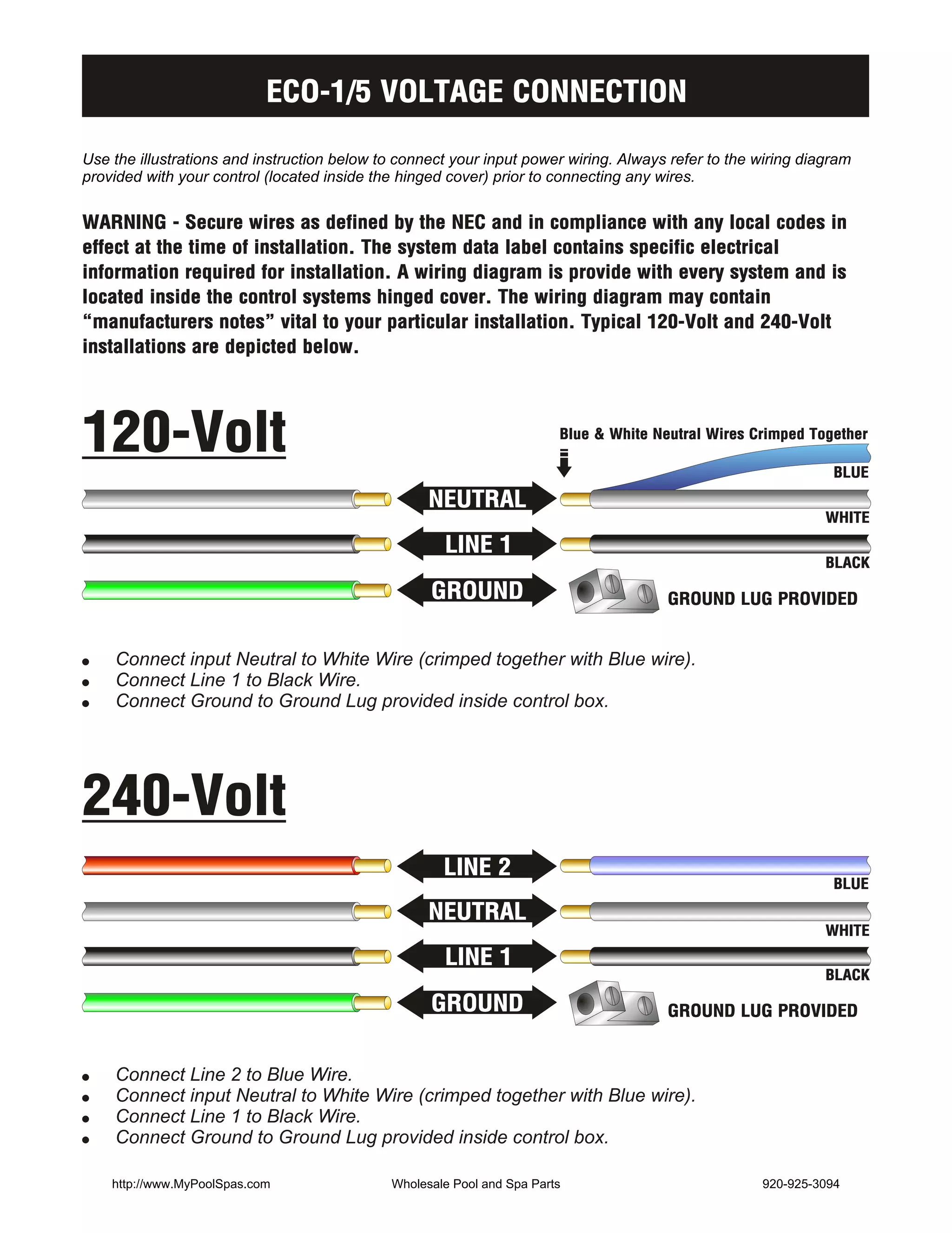

The document provides instructions for connecting the input power wiring for an ECO-1/5 voltage control system. It describes how to connect the neutral, line 1, line 2, and ground wires for both 120V and 240V installations. The document also includes warnings to follow electrical codes and refer to the provided wiring diagram.


