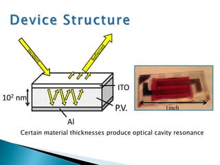
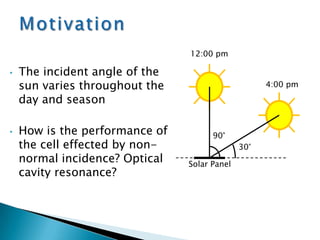
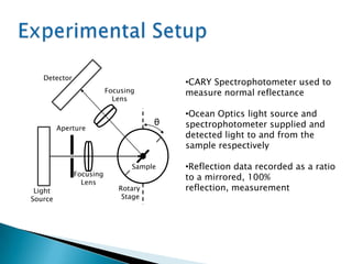
This document discusses how the performance of organic solar cells is affected by the incident angle of sunlight. It presents experimental data showing how reflection spectra change with varying incidence angles, and compares this to simulations. Key findings include:
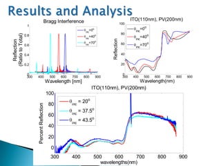
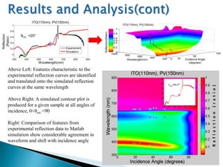
1) Simulation and experiment agree that most spectral features remain largely unchanged across a range of incidence angles, though absorption peaks can shift up to 40nm.
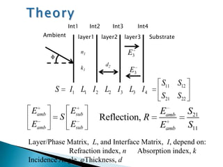
2) A generalized simulation model is developed that can predict reflection spectra for any incident angle, matching experimental observations.
3) While performance varies some with changing sunlight angles through the day and seasons, organic solar cells maintain efficiency relatively well compared to conventional silicon cells.