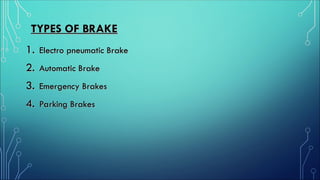
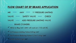
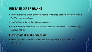
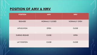
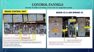
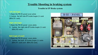
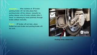
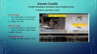
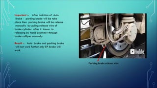
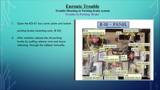
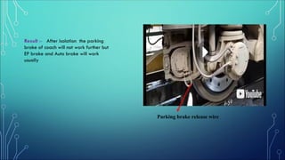
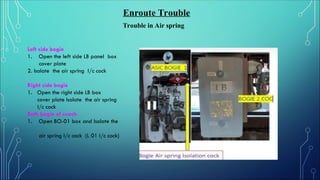
BRAKE SYSTEM
TYPES OF BRAKE
TYPES OF BRAKE
1.
1. Electro pneumatic Brake
Electro pneumatic Brake
2.
2. Automatic Brake
Automatic Brake
3.
3. Emergency Brakes
Emergency Brakes
4.
4. Parking Brakes
Parking Brakes
ELECTRO PNEUMATIC BRAKE
WHY EP BRAKE REQUIRED
• Both Electric & Pneumatic brakes are available and can be used
Both Electric & Pneumatic brakes are available and can be used
independently.
independently.
• Braking more effective. Both application & Release car be
Braking more effective. Both application & Release car be
graduated in steps & can be achieved Application & Release also.
• All the Valves are mounted on a single Bracket
All the Valves are mounted on a single Bracket
• Trouble Shooting & Maintenance is easy
Trouble Shooting & Maintenance is easy
• On application of Electrical Brake, no BP pressure will be dropped
On application of Electrical Brake, no BP pressure will be dropped
hence loading of the Compressor is less.
MAIN COMPONENT OF EP BRAKE
• APPLICATION OF MAGNET VALVE(AMV)
APPLICATION OF MAGNET VALVE(AMV)
• HOLDING MAGNET VALVE(HMV)
HOLDING MAGNET VALVE(HMV)
• SAFETY VALVE
SAFETY VALVE
• TRIPLE VALVE
TRIPLE VALVE
• PRESSURE LIMITING VALVE
PRESSURE LIMITING VALVE
• STABILISING VALVE
STABILISING VALVE
• CHECK VALVE
CHECK VALVE
FUNCTION OF MAIN COMPONENTS
Triple valve (TV)-
•This valve is responsible for Auto brake system
This valve is responsible for Auto brake system
•During Application it supplies compressed air to brake cylinder(BC) by
During Application it supplies compressed air to brake cylinder(BC) by
connecting the auxiliary reservoir to BC line when there is a drop in brake pipe
pressure
pressure
Pressure Limiting valve(PLV)-
•The function of the pressure limiting valve is to limit the air pressure in MR pipe
The function of the pressure limiting valve is to limit the air pressure in MR pipe
line to a specified value(3.8kg/
line to a specified value(3.8kg/cm2
).
).
Application magnet valve(AMV)-
•During EP brake application, this valve connects MR line to BC line and thus
During EP brake application, this valve connects MR line to BC line and thus
supplies compressed air to brake cylinder required for brake application
•During Release, the port of AMV is in Closed position
During Release, the port of AMV is in Closed position
Holding magnet valve(HMV)-
•During EP brake application this valve closes.
During EP brake application this valve closes.
•During Release, HMV open & Air of BC pressure releases to atmosphere.
During Release, HMV open & Air of BC pressure releases to atmosphere.
APPLICATION OF EP BRAKE
 When moves the brake controller handle to EP
position, then both HMV & AMV get energized.
 HMV holds the brake cylinder pressure.
 AMV allows MR pressure to Brake Cylinder through Valves.
 Air Flow
MR Pressure AMV Limiting Valve (PLV)
Safety Valve NRV Additional Limiting Valve (ALV) BC.
FLOW CHART OF EP BRAKE APPLICATION
MR AMV 1
MR AMV 1st
st
PRESSURE LIMITING
PRESSURE LIMITING
VALVE SAFETY VALVE CHECK
VALVE ADD PRESSURE LIMITING VALVE
BRAKE CYLINDER.
BRAKE CYLINDER.
 MR-6 to 8kg/
MR-6 to 8kg/cm2
. AMV will work at -110 volt DC
1st Pressure Limiting Valve-3.8 kg/
1st Pressure Limiting Valve-3.8 kg/cm2
2nd Pressure Reducing Valve-1.2 to 1 6 kg/
2nd Pressure Reducing Valve-1.2 to 1 6 kg/cm2
Safety Valve-4 kg/
Safety Valve-4 kg/cm2
RELEASE OF EP BRAKE
RELEASE OF EP BRAKE
• When moves the brake controller handle to release position, then both HMV &
When moves the brake controller handle to release position, then both HMV &
AMV get de-energized.
• HMV exhausts the brake cylinder pressure
HMV exhausts the brake cylinder pressure
• AMV blocks MR pressure & not to allow pressure into Brake Cylinder through
AMV blocks MR pressure & not to allow pressure into Brake Cylinder through
Various Valves.
Various Valves.
Flow chart of brake releasing
• Brake Cylinder Pressure
Brake Cylinder Pressure ->
-> Additional Limiting Valve(ALV)
Additional Limiting Valve(ALV) ->
-> HMV
HMV ->
->
atmosphere
atmosphere.
.
POSITION OF AMV & HMV
POSITION AMV HMV
RELEASED NORMALLY CLOSED NORMALLY OPEN
APPLICATION OPEN CLOSE
DURING RELEASE CLOSE OPEN
LAP POSITION CLOSE CLOSE
AUTOMATIC BRAKE
SYSTEM
APPLICATION
APPLICATION
•Reduces BP pressure through Exhaust port of Triple
Reduces BP pressure through Exhaust port of Triple
Valve to Atmosphere & Pressure from Auxiliary
Reservoir Triple
Reservoir Triple ->
-> Valve port D to Port C
Valve port D to Port C ->
->
Additional Limiting Valve
Additional Limiting Valve ->
-> Safety Valve
Safety Valve ->
-> Brake
Brake
Cylinder
Cylinder
RELEASE
RELEASE
•When motorman moves the brake controller handle to
When motorman moves the brake controller handle to
release position, upper chamber of valve gets charged
from BP and it's diaphragm moves downward
•This charging in BP pipe is sensed by triple valve which
This charging in BP pipe is sensed by triple valve which
connects B port to C port and exhausts BC to atmosphere
through HMV and safety valve
through HMV and safety valve.
.
AUTOMATIC BRAKE
AUTOMATIC BRAKE
EMERGENCY BRAKE
SYSTEM
Emergency brake
 Equipped with emergency brake loop wire.
 Initiated with the master controller on drivers desk.
 If the emergency brake loop is opened, the emergency brake valves will be de-
energized and make the emergency brake pressure work.
 Redundancy realized for the emergency brake pressure generation via the digital
control valve (DCL) since the BECU receives emergency brake command from
emergency loop as well.
 Is load corrected via the load dependent pressure limiting valve in the BCU.
PARKING BRAKE
SYSTEM
Parking brake control (Panel B01)
Brake Modes IV
System overview
A parking brake application is a brake application
for stopping a
stationary train from rolling under set conditions for
as long as required
until the brake is released.
 The parking brake is release,
when the spring actuators are vented.
 Controlled by the impulse magnet
valve, which needs a short train line
impulse from the driver
The parking brake applies or
Releases
It can be also manually operated
Always applied in the event of
loss of MR- pipe pressure
Parking brake
TROUBLE SHOOTING
TROUBLE SHOOTING
CONTROL PANNELS
Enroute Trouble in braking system and Air suspension system
Trouble Shooting in braking system
Trouble in EP Brake system
Left side bogie
1.Open the PB 02 panel cover plate
2. Isolate the left side EP brake bogie I/c cock
(B04/01 cock).
Right side bogie
1.Open the PB 02 panel cover plate
2. Isolate the right side EP brake bogie I/c cock
(B04/02 cock).
Both bogie of coach
1.Open the PB 02 panel cover plate
2. Isolate the both EP brake bogie I/c cocks
(B04/01 cock) and (B04/02 cock).
Important :- After isolation of EP brake-
parking brake will be take place then
parking brake will be release manually by
puling release wire of brake cylinder after it
insure to releasing by hand positively through
brake calliper manually.
Result :- EP brake will not take place
further but auto brake and parking brake will
be work.
Parking brake release wire
Enroute Trouble
Trouble Shooting in automatic (auto) braking system
Trouble in Auto Brake system
Left side bogie
1. Go to left bogie I/c cock situated
near by LB panel of left bogie
2. Isolate the same.
Right side bogie
1. Go to left bogie I/c cock situated
near by LB panel of right bogie
2.Isolate the same.
Both bogie of coach
1. Isolate the both bogie I/c cocks.
Important :- After isolation of Auto
Brake - parking brake will be take
place then parking brake will be release
manually by puling release wire of
brake cylinder after it insure to
releasing by hand positively through
brake calliper manually.
Result :- Auto brake and parking brake
will not work further only EP brake will
work.
Parking brake release wire
Enroute Trouble
Trouble Shooting in Parking brake system
Trouble in Parking Brake
1. Open the BO-01 box cover plate and Isolate
parking brake insolating cock. (B 05)
2. After isolation release the all parking
brake by pulling release wire and insure
releasing through the calliper manually.
Result :- After isolation the parking
brake of coach will not work further but
EP brake and Auto brake will work
usually
Parking brake release wire
Enroute Trouble
Trouble in Air spring
Left side bogie
1. Open the left side LB panel box
cover plate
2. Isolate the air spring I/c cock
Right side bogie
1. Open the right side LB box
cover plate Isolate the air spring
I/c cock
Both bogie of coach
1. Open BO-01 box and Isolate the
air spring I/c cock (L 01 I/c cock)
Both bogie of coach
1. Open BO-01 box and Isolate the
air spring I/c cock (L 01 I/c cock)
2. Isolate the both EP brake
bogie I/c cocks
Result :- Train will run further
with 60 Kmph speed limit
Parking brake release wire
THANKS
THANKS

VANDE BHARAT BRAKE SYSTEM VERY IMPORTANT

  • 1.
  • 2.
    TYPES OF BRAKE TYPESOF BRAKE 1. 1. Electro pneumatic Brake Electro pneumatic Brake 2. 2. Automatic Brake Automatic Brake 3. 3. Emergency Brakes Emergency Brakes 4. 4. Parking Brakes Parking Brakes
  • 3.
  • 4.
    WHY EP BRAKEREQUIRED WHY EP BRAKE REQUIRED • Both Electric & Pneumatic brakes are available and can be used Both Electric & Pneumatic brakes are available and can be used independently. independently. • Braking more effective. Both application & Release car be Braking more effective. Both application & Release car be graduated in steps & can be achieved Application & Release also. graduated in steps & can be achieved Application & Release also. • All the Valves are mounted on a single Bracket All the Valves are mounted on a single Bracket • Trouble Shooting & Maintenance is easy Trouble Shooting & Maintenance is easy • On application of Electrical Brake, no BP pressure will be dropped On application of Electrical Brake, no BP pressure will be dropped hence loading of the Compressor is less. hence loading of the Compressor is less.
  • 5.
    MAIN COMPONENT OFEP BRAKE MAIN COMPONENT OF EP BRAKE • APPLICATION OF MAGNET VALVE(AMV) APPLICATION OF MAGNET VALVE(AMV) • HOLDING MAGNET VALVE(HMV) HOLDING MAGNET VALVE(HMV) • SAFETY VALVE SAFETY VALVE • TRIPLE VALVE TRIPLE VALVE • PRESSURE LIMITING VALVE PRESSURE LIMITING VALVE • STABILISING VALVE STABILISING VALVE • CHECK VALVE CHECK VALVE
  • 6.
    FUNCTION OF MAINCOMPONENTS FUNCTION OF MAIN COMPONENTS Triple valve (TV)- •This valve is responsible for Auto brake system This valve is responsible for Auto brake system •During Application it supplies compressed air to brake cylinder(BC) by During Application it supplies compressed air to brake cylinder(BC) by connecting the auxiliary reservoir to BC line when there is a drop in brake pipe connecting the auxiliary reservoir to BC line when there is a drop in brake pipe pressure pressure Pressure Limiting valve(PLV)- •The function of the pressure limiting valve is to limit the air pressure in MR pipe The function of the pressure limiting valve is to limit the air pressure in MR pipe line to a specified value(3.8kg/ line to a specified value(3.8kg/cm2 ). ).
  • 7.
    Application magnet valve(AMV)- •DuringEP brake application, this valve connects MR line to BC line and thus During EP brake application, this valve connects MR line to BC line and thus supplies compressed air to brake cylinder required for brake application supplies compressed air to brake cylinder required for brake application •During Release, the port of AMV is in Closed position During Release, the port of AMV is in Closed position Holding magnet valve(HMV)- •During EP brake application this valve closes. During EP brake application this valve closes. •During Release, HMV open & Air of BC pressure releases to atmosphere. During Release, HMV open & Air of BC pressure releases to atmosphere.
  • 8.
    APPLICATION OF EPBRAKE  When moves the brake controller handle to EP position, then both HMV & AMV get energized.  HMV holds the brake cylinder pressure.  AMV allows MR pressure to Brake Cylinder through Valves.  Air Flow MR Pressure AMV Limiting Valve (PLV) Safety Valve NRV Additional Limiting Valve (ALV) BC.
  • 9.
    FLOW CHART OFEP BRAKE APPLICATION FLOW CHART OF EP BRAKE APPLICATION MR AMV 1 MR AMV 1st st PRESSURE LIMITING PRESSURE LIMITING VALVE SAFETY VALVE CHECK VALVE SAFETY VALVE CHECK VALVE ADD PRESSURE LIMITING VALVE VALVE ADD PRESSURE LIMITING VALVE BRAKE CYLINDER. BRAKE CYLINDER.  MR-6 to 8kg/ MR-6 to 8kg/cm2 . AMV will work at -110 volt DC . AMV will work at -110 volt DC 1st Pressure Limiting Valve-3.8 kg/ 1st Pressure Limiting Valve-3.8 kg/cm2 2nd Pressure Reducing Valve-1.2 to 1 6 kg/ 2nd Pressure Reducing Valve-1.2 to 1 6 kg/cm2 Safety Valve-4 kg/ Safety Valve-4 kg/cm2
  • 10.
    RELEASE OF EPBRAKE RELEASE OF EP BRAKE • When moves the brake controller handle to release position, then both HMV & When moves the brake controller handle to release position, then both HMV & AMV get de-energized. AMV get de-energized. • HMV exhausts the brake cylinder pressure HMV exhausts the brake cylinder pressure • AMV blocks MR pressure & not to allow pressure into Brake Cylinder through AMV blocks MR pressure & not to allow pressure into Brake Cylinder through Various Valves. Various Valves. Flow chart of brake releasing Flow chart of brake releasing • Brake Cylinder Pressure Brake Cylinder Pressure -> -> Additional Limiting Valve(ALV) Additional Limiting Valve(ALV) -> -> HMV HMV -> -> atmosphere atmosphere. .
  • 11.
    POSITION OF AMV& HMV POSITION OF AMV & HMV POSITION AMV HMV RELEASED NORMALLY CLOSED NORMALLY OPEN APPLICATION OPEN CLOSE DURING RELEASE CLOSE OPEN LAP POSITION CLOSE CLOSE
  • 12.
  • 13.
    APPLICATION APPLICATION •Reduces BP pressurethrough Exhaust port of Triple Reduces BP pressure through Exhaust port of Triple Valve to Atmosphere & Pressure from Auxiliary Valve to Atmosphere & Pressure from Auxiliary Reservoir Triple Reservoir Triple -> -> Valve port D to Port C Valve port D to Port C -> -> Additional Limiting Valve Additional Limiting Valve -> -> Safety Valve Safety Valve -> -> Brake Brake Cylinder Cylinder
  • 14.
    RELEASE RELEASE •When motorman movesthe brake controller handle to When motorman moves the brake controller handle to release position, upper chamber of valve gets charged release position, upper chamber of valve gets charged from BP and it's diaphragm moves downward from BP and it's diaphragm moves downward •This charging in BP pipe is sensed by triple valve which This charging in BP pipe is sensed by triple valve which connects B port to C port and exhausts BC to atmosphere connects B port to C port and exhausts BC to atmosphere through HMV and safety valve through HMV and safety valve. .
  • 15.
  • 16.
  • 17.
    Emergency brake  Equippedwith emergency brake loop wire.  Initiated with the master controller on drivers desk.  If the emergency brake loop is opened, the emergency brake valves will be de- energized and make the emergency brake pressure work.  Redundancy realized for the emergency brake pressure generation via the digital control valve (DCL) since the BECU receives emergency brake command from emergency loop as well.  Is load corrected via the load dependent pressure limiting valve in the BCU.
  • 18.
  • 19.
    Parking brake control(Panel B01) Brake Modes IV System overview A parking brake application is a brake application for stopping a stationary train from rolling under set conditions for as long as required until the brake is released.  The parking brake is release, when the spring actuators are vented.  Controlled by the impulse magnet valve, which needs a short train line impulse from the driver The parking brake applies or Releases It can be also manually operated Always applied in the event of loss of MR- pipe pressure Parking brake
  • 20.
  • 21.
    CONTROL PANNELS Enroute Troublein braking system and Air suspension system
  • 22.
    Trouble Shooting inbraking system Trouble in EP Brake system Left side bogie 1.Open the PB 02 panel cover plate 2. Isolate the left side EP brake bogie I/c cock (B04/01 cock). Right side bogie 1.Open the PB 02 panel cover plate 2. Isolate the right side EP brake bogie I/c cock (B04/02 cock). Both bogie of coach 1.Open the PB 02 panel cover plate 2. Isolate the both EP brake bogie I/c cocks (B04/01 cock) and (B04/02 cock).
  • 23.
    Important :- Afterisolation of EP brake- parking brake will be take place then parking brake will be release manually by puling release wire of brake cylinder after it insure to releasing by hand positively through brake calliper manually. Result :- EP brake will not take place further but auto brake and parking brake will be work. Parking brake release wire
  • 24.
    Enroute Trouble Trouble Shootingin automatic (auto) braking system Trouble in Auto Brake system Left side bogie 1. Go to left bogie I/c cock situated near by LB panel of left bogie 2. Isolate the same. Right side bogie 1. Go to left bogie I/c cock situated near by LB panel of right bogie 2.Isolate the same. Both bogie of coach 1. Isolate the both bogie I/c cocks.
  • 25.
    Important :- Afterisolation of Auto Brake - parking brake will be take place then parking brake will be release manually by puling release wire of brake cylinder after it insure to releasing by hand positively through brake calliper manually. Result :- Auto brake and parking brake will not work further only EP brake will work. Parking brake release wire
  • 26.
    Enroute Trouble Trouble Shootingin Parking brake system Trouble in Parking Brake 1. Open the BO-01 box cover plate and Isolate parking brake insolating cock. (B 05) 2. After isolation release the all parking brake by pulling release wire and insure releasing through the calliper manually.
  • 27.
    Result :- Afterisolation the parking brake of coach will not work further but EP brake and Auto brake will work usually Parking brake release wire
  • 28.
    Enroute Trouble Trouble inAir spring Left side bogie 1. Open the left side LB panel box cover plate 2. Isolate the air spring I/c cock Right side bogie 1. Open the right side LB box cover plate Isolate the air spring I/c cock Both bogie of coach 1. Open BO-01 box and Isolate the air spring I/c cock (L 01 I/c cock)
  • 29.
    Both bogie ofcoach 1. Open BO-01 box and Isolate the air spring I/c cock (L 01 I/c cock) 2. Isolate the both EP brake bogie I/c cocks
  • 30.
    Result :- Trainwill run further with 60 Kmph speed limit Parking brake release wire
  • 31.