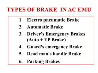
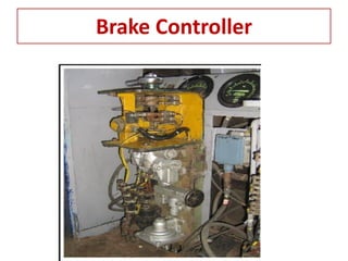
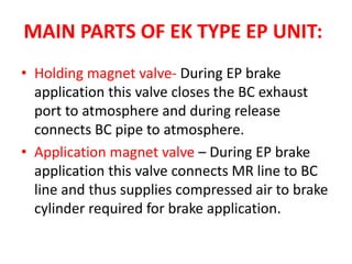
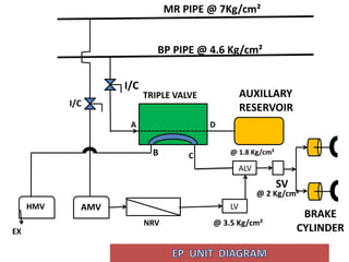
BRAKE SYTEM IN AC EMU
TYPES OF BRAKE IN AC EMU
1. Electro pneumatic Brake
2. Automatic Brake
3. Driver’s Emergency Brakes
(Auto + EP Brake)
4. Guard's emergency Brake
5. Dead man's handle Brake
6. Parking Brakes
Brake Equipments
1. Brake Controller
2. EP Unit
3. Brake Rigging( Brake Block
to brake cylinder parts)
Brake controller
EP LAP
AUTO
EMERGENCY
RELEASE
ICS
5
BRAKE CONTROLLER
Brake Controller
A C
D
B
Ex
ICS
Reducing
valve
BP pipe
EDV
Ex
Ex
UC
LC
Diaphragm
BP PIPE @ 4.6Kg/cm²
MR PIPE @ 7Kg/cm²
Poppet Valves
A B C Ex D Ex
Release Open Open Close Close
Auto Close Close Open Close
LAP Close Close Close Close
EB Close Close Open Open
MAIN PARTS OF EK TYPE EP UNIT:
• Holding magnet valve- During EP brake
application this valve closes the BC exhaust
port to atmosphere and during release
connects BC pipe to atmosphere.
• Application magnet valve – During EP brake
application this valve connects MR line to BC
line and thus supplies compressed air to brake
cylinder required for brake application.
• Triple valve –This valve is responsible for auto
brake application and supplies compressed air
to brake cylinder by connecting the auxiliary
reservoir to BC line when there is a drop in
brake pipe pressure.
• Limiting valve- The function of the pressure
limiting valve is to limit the air pressure in BC
pipe line to a specified value (3.2kg/cm2).
MAIN PARTS OF EK TYPE EP UNIT:
• Safety valve- This valve protects the brake
cylinder line from over-pressure thus
preventing consequent damage on brake-
block and wheel.
• Non-return valve-This valve is used to provide
unidirectional path for air flow.
MAIN PARTS OF EK TYPE EP UNIT:
MR PIPE @ 7Kg/cm²
BP PIPE @ 4.6 Kg/cm²
TRIPLE VALVE AUXILLARY
RESERVOIR
HMV AMV
NRV
LV
ALV
SV
EX
BRAKE
CYLINDER
I/C
I/C
@ 3.5 Kg/cm²
@ 1.8 Kg/cm²
@ 2 Kg/cm²
B C
D
A
• When motorman moves the brake controller
handle to EP position, then both HMV & AMV
get energized.
• HMV holds the brake cylinder pressure.
• AMV allows MR pressure to Brake Cylinder
through Various Valves.
• Air Flow
MR Pressure → AMV → NRV → Limiting Valve
(LV)→ Additional Limiting Valve (ALV)→ Safety
Valve → Brake Cylinder
ELECTRO PNEUMATIC BRAKE
• When motorman moves the brake controller
handle to release position, then both HMV &
AMV get de-energized.
• HMV exhausts the brake cylinder pressure.
• AMV blocks MR pressure to Brake Cylinder
through Various Valves.
• Air Flow
Brake Pressure → Additional Limiting Valve
(ALV)→ HMV→atmosphere
RELEASE OF EP BRAKE
• When motorman moves the brake controller
handle to Auto position, poppet valve A& B
close and poppet Valve C’s exhaust gets open
then upper chamber of EDV valve gets
exhausted and it’s diaphragm moves upward
and it’s exhaust port gets open and BP pressure
starts reducing
• This Reduction in BP pressure is sensed by
tripple valve which connects D port to C port
and allows auxiliary reservoir pressure to brake
cylinder through ALV and safety valve.
APPLICATION AUTOMATIC BRAKE
• Air Flow
Pressure from Auxiliary Reservoir Triple
Valve port D to Port C  Additional Limiting
Valve  Safety Valve  Brake Cylinder
APPLICATION AUTOMATIC BRAKE
• When motorman moves the brake controller
handle to release position, poppet valve A& B
open and poppet Valve C’s exhaust gets closed
then upper chamber of EDV valve gets charged
and it’s diaphragm moves downward and it’s
exhaust port gets closed and BP pressure starts
charging.
• This charging in BP pipe is sensed by tripple
valve which connects B port to C port and
exhausts brake cylinder through ALV and safety
valve.
RELEASE OF AUTOMATIC BRAKE
APPLICATION OF EMERGENCY BRAKE
• During Driver’s emergency brake application
BP pressure is destroyed to actuate Auto brake
application with EP brake simultaneously.
RELEASE EMERGENCY BRAKE
• When motorman moves the brake controller
handle to release position, EP and Auto brake
are released.
PARKING BRAKE
• The parking brake is provided to prevent the
train from inadvertent rolling, if the normal
brake looses its effect by having too less air
pressure in the MR pipe during standstill
condition
• Every axle of the DMC coach has an
additional parking brake.
PARKING BRAKE
• Parking brake is applied using power of a
spring and is released by using power of air.
• The parking brake is activated in standstill
only.
• It is only possible to release the parking brake
when a certain minimum air pressure is
reached in the MR PIPE
Working principle
The parking brakes are electro-pneumatically
operated through the solenoid valve and
separate brake cylinders. The brakes are
applied on the following wheel positions.
Position 1 axle wheel No. 1
Position 2 axle wheel No. 3
Position 3 axle wheel No. 5
Position 4 axle wheel No. 7
Parking brake air circuit
Application of parking brake
1. When Motorman switches on the knob
switch for parking brake, the solenoid valve
gets de-energized which stops the air
pressure supply to parking brake cylinder
and opens the vent for exhaust of the air
pressure from the parking brake cylinder.
2. The cylinder operates (without air) and apply
the parking brake
PARKING BRAKE
• When the air pressure in the parking brake air
pipe is higher than 3 bar the parking brake is
released.
• When the air pressure in the parking brake air
pipe is less than 2 bar the parking brake is
applied
Release of Parking Brake
• As soon as the motorman switches off the
knob for parking brake, the solenoid valve
gets energized allows the MR pressure to the
parking brake cylinder through a reducing
valve and release the brake.
Parking brake electrical circuit
Parking brake air circuit
Application of Parking Brake
• For applying the parking brake, operate
the push button for parking brake
application provided in front of the
Motorman’s desk.
• On pressing the push button, back light
with parking brake applied symbol will
illuminate.
BRAKE SYSTEM(Electric multiple unit).pdf

BRAKE SYSTEM(Electric multiple unit).pdf

  • 1.
  • 2.
    TYPES OF BRAKEIN AC EMU 1. Electro pneumatic Brake 2. Automatic Brake 3. Driver’s Emergency Brakes (Auto + EP Brake) 4. Guard's emergency Brake 5. Dead man's handle Brake 6. Parking Brakes
  • 3.
    Brake Equipments 1. BrakeController 2. EP Unit 3. Brake Rigging( Brake Block to brake cylinder parts)
  • 4.
  • 5.
  • 6.
  • 7.
    A C D B Ex ICS Reducing valve BP pipe EDV Ex Ex UC LC Diaphragm BPPIPE @ 4.6Kg/cm² MR PIPE @ 7Kg/cm² Poppet Valves A B C Ex D Ex Release Open Open Close Close Auto Close Close Open Close LAP Close Close Close Close EB Close Close Open Open
  • 9.
    MAIN PARTS OFEK TYPE EP UNIT: • Holding magnet valve- During EP brake application this valve closes the BC exhaust port to atmosphere and during release connects BC pipe to atmosphere. • Application magnet valve – During EP brake application this valve connects MR line to BC line and thus supplies compressed air to brake cylinder required for brake application.
  • 10.
    • Triple valve–This valve is responsible for auto brake application and supplies compressed air to brake cylinder by connecting the auxiliary reservoir to BC line when there is a drop in brake pipe pressure. • Limiting valve- The function of the pressure limiting valve is to limit the air pressure in BC pipe line to a specified value (3.2kg/cm2). MAIN PARTS OF EK TYPE EP UNIT:
  • 11.
    • Safety valve-This valve protects the brake cylinder line from over-pressure thus preventing consequent damage on brake- block and wheel. • Non-return valve-This valve is used to provide unidirectional path for air flow. MAIN PARTS OF EK TYPE EP UNIT:
  • 12.
    MR PIPE @7Kg/cm² BP PIPE @ 4.6 Kg/cm² TRIPLE VALVE AUXILLARY RESERVOIR HMV AMV NRV LV ALV SV EX BRAKE CYLINDER I/C I/C @ 3.5 Kg/cm² @ 1.8 Kg/cm² @ 2 Kg/cm² B C D A
  • 14.
    • When motormanmoves the brake controller handle to EP position, then both HMV & AMV get energized. • HMV holds the brake cylinder pressure. • AMV allows MR pressure to Brake Cylinder through Various Valves. • Air Flow MR Pressure → AMV → NRV → Limiting Valve (LV)→ Additional Limiting Valve (ALV)→ Safety Valve → Brake Cylinder ELECTRO PNEUMATIC BRAKE
  • 15.
    • When motormanmoves the brake controller handle to release position, then both HMV & AMV get de-energized. • HMV exhausts the brake cylinder pressure. • AMV blocks MR pressure to Brake Cylinder through Various Valves. • Air Flow Brake Pressure → Additional Limiting Valve (ALV)→ HMV→atmosphere RELEASE OF EP BRAKE
  • 16.
    • When motormanmoves the brake controller handle to Auto position, poppet valve A& B close and poppet Valve C’s exhaust gets open then upper chamber of EDV valve gets exhausted and it’s diaphragm moves upward and it’s exhaust port gets open and BP pressure starts reducing • This Reduction in BP pressure is sensed by tripple valve which connects D port to C port and allows auxiliary reservoir pressure to brake cylinder through ALV and safety valve. APPLICATION AUTOMATIC BRAKE
  • 17.
    • Air Flow Pressurefrom Auxiliary Reservoir Triple Valve port D to Port C  Additional Limiting Valve  Safety Valve  Brake Cylinder APPLICATION AUTOMATIC BRAKE
  • 18.
    • When motormanmoves the brake controller handle to release position, poppet valve A& B open and poppet Valve C’s exhaust gets closed then upper chamber of EDV valve gets charged and it’s diaphragm moves downward and it’s exhaust port gets closed and BP pressure starts charging. • This charging in BP pipe is sensed by tripple valve which connects B port to C port and exhausts brake cylinder through ALV and safety valve. RELEASE OF AUTOMATIC BRAKE
  • 19.
    APPLICATION OF EMERGENCYBRAKE • During Driver’s emergency brake application BP pressure is destroyed to actuate Auto brake application with EP brake simultaneously.
  • 20.
    RELEASE EMERGENCY BRAKE •When motorman moves the brake controller handle to release position, EP and Auto brake are released.
  • 22.
    PARKING BRAKE • Theparking brake is provided to prevent the train from inadvertent rolling, if the normal brake looses its effect by having too less air pressure in the MR pipe during standstill condition • Every axle of the DMC coach has an additional parking brake.
  • 23.
    PARKING BRAKE • Parkingbrake is applied using power of a spring and is released by using power of air. • The parking brake is activated in standstill only. • It is only possible to release the parking brake when a certain minimum air pressure is reached in the MR PIPE
  • 24.
    Working principle The parkingbrakes are electro-pneumatically operated through the solenoid valve and separate brake cylinders. The brakes are applied on the following wheel positions. Position 1 axle wheel No. 1 Position 2 axle wheel No. 3 Position 3 axle wheel No. 5 Position 4 axle wheel No. 7
  • 25.
  • 26.
    Application of parkingbrake 1. When Motorman switches on the knob switch for parking brake, the solenoid valve gets de-energized which stops the air pressure supply to parking brake cylinder and opens the vent for exhaust of the air pressure from the parking brake cylinder. 2. The cylinder operates (without air) and apply the parking brake
  • 27.
    PARKING BRAKE • Whenthe air pressure in the parking brake air pipe is higher than 3 bar the parking brake is released. • When the air pressure in the parking brake air pipe is less than 2 bar the parking brake is applied
  • 28.
    Release of ParkingBrake • As soon as the motorman switches off the knob for parking brake, the solenoid valve gets energized allows the MR pressure to the parking brake cylinder through a reducing valve and release the brake.
  • 29.
  • 30.
  • 31.
    Application of ParkingBrake • For applying the parking brake, operate the push button for parking brake application provided in front of the Motorman’s desk. • On pressing the push button, back light with parking brake applied symbol will illuminate.