4
CONCEPT
PRESENT SCENARIO
IR HAVINGSELF PROPELLED TRAIN SETS SUCH AS MRVC , DMU, MEMU,EMU
ETC SPEED POTENTIAL OF THIS TRAIN SETS.
• DEMU/DPC & TC : 95/105 kmph
• Kolkata Metro 55/80 kmph
• AC EMU –MUTP 110 kmph (Bombardier)
• AC/DCEMU-MRVC 100 kmph ( Siemens
Developments in Road sector Golden Quadrilateral and Bharathmala
projects.
The speed potential of high way traffic increased many fold.
Now passenger vehicles runs at 100- 180 Kmph speed at Express High ways.Railways to
increase speed potential to 200Kmph (semi high speed) at first stage and 350+
Kmph (high
speed) at stage -2
• The speed potential of high way traffic increased many fold.
• Now passenger vehicles runs at 100- 180 Kmph speed at Express High ways.
• Railways to increase speed potential to 200Kmph (semi high speed) at first stage and
350+
Kmph (high speed) at stage -2
INDIAN RAILWAY MOVING TOWARDS HIGHER SPEED
• WORK ON FULL SWING FOR MUMBAI-AHMEDHABAD HIGH SPEED
CORRIDOR 350 KMPH
• Speed Trail run with TALGO coaches with articulated Bogie conducted at 200KMPH
• TRAIN 18 IN MAKE IN INDIA 160 KMPH
ACCELERATION AND DECELERATION
PRESENT EMU : 0.54 & 0.84 M/SEC2
FOR TRAIN 18 : 0.8M/Sec2
METRO : 0.85 & 1.5 M/Sec2
5.
5
ALL PROPULSION EQUIPMENTSARE UNDERSLUNG
TRAIN 18
Powered coaches : 50 %
EMU POWERED COACHES : 33%
CONCEPTS :
1. BOGIE
2. SHELL
3. FURNISHING
BOGIE :-
• BOLSTERLESS DESIGN
• FULLY SUSPENDED TRACTION MOTOR
• DISC BRAKE WITH BRAKE DISC ON WHEEL
• AIR SPRING ON SECONDARY SUSPENSION
Body shell conc
CONSULTANT : EC ENGINEERING POLAND
FRP SKIN NOSE CONE
CONSULTANT BFG
6.
6
1. UNDERFRAME
More orless similar to LHB
• Material : up to 10mm thickness IRS M 41
• Material: above 10 mm thickness EN 10025
• SOLE BAR SECTION SAME AS THAT OF LHB(6MM)BODY BOLSTER WITH NON
REMOVABLE SPIGOT FOR AIR SUPPLY TO AIR SPRING
• Head stock with lowered location of semi permanent coupler ( 860 mm from Rail level)
2. SIDE WALL
3. ROOF
4. END WALL
Side wall , Roof and End wall of Stainless steel Specification RDSO CK 201 X2CrNi 12
Thickness 1.6 , 2, 3 & 5 mm.
Furnishing
• World class furnishing , consultancy by Global players
• Entrance door with Retractable foot step and Plug in -plug out door- KNOR
BREMSE
• Continuous Window which seems like a single window from out side –consultancy
YELLOW WINDOW
• Panels and interiors- consultancy BFG
• Fully sealed gangway and exterior shroud – consultant HUBNER
• Vacuum assisted Bio Toilets – consultant - Evac
• Seats - FAINSA
• ELECTRICS BY MEDHA
7.
7
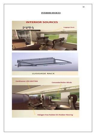
• Indirect LEDlights on Luggage Racks and AC Ducts – BFG
• Special air conditioning duct for silent and equal distribution of conditioned Airb
BFG
• Provision of entertainment and mobile charging at every seat.
• Revolving seats at Executive class
• ON BOARD INFOTAINMENT WIFI
• GPS BASED PASSENGER INFORMATION SYSTEM
• All coaches having ONE onboard PANTRY
SPECIAL PROVISION IN DTC FOR PERSONS WITH DISABILITY
Place for wheel chair and Special lavatory
PLUG DOOR
RETRACTABLE
FOOT STEP
8.
8
RAKE FORMATION
Multiple unitsformed joining Basic units of 4 ca
• 16 CAR DOUBLE HEADED TRAIN SET
• 8 MOTOR CAR,
• 4 TRAILER CAR
• 2 Non DRIVING TRAILER CAR
• 2 DRIVING TRAILER CAR
• ALL COACHES ARE CHAIR CARS
• Out of 16 coaches , 2 coaches are Executive Class
• TRAILER CAR HAVE PANTO above roof and UNDERSUNG TRANSFORMER
to cater 2 MOTOR COACHES.
• AUX CONVERTER ALSO IN TC
• DTC AND NDTC HAVING BATTERY & CHARGER
• MOTOR COACH HAVE TRACTION CONVERTER
• ALL Coaches have Brake Skid( End & Middle) and isolating Transformer for pantry
load
• Under slung Water tank capacity 1200Lts approx
• Pre wired Cables trays on under frame for power and control cables
12
• To ''Makein India'' Best In Class Train sets in the existing facilities of IR at Half the
cost
• The 160 Kmph Trainset with Driving Cab at both Ends - will have all propulsion
equipment under-slung and all coaches inter connected with fully sealed gangways.
End Basic Unit
26
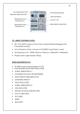
TC - RMPUCONTROL PANEL
· MC, TC & NDTC coaches of Train 18 have one Roof Mounted Packaging Unit's
Control Panel on board.
· 16 Car formation of Train- 18 houses 14 TC-RMPU Control Panels in total.
· The dimensions of TC - RMPU Panel are 750mm (L) x 200mm(W) x 1800mm(H).
· Weight of each is approximately 100 kgs.
ROOF EQUIPMENTS TC
· TC RMPU panel is mounted adjacent to ECC.
· PANTOGRAPH WITH FOOT INSULATOR
· SURGE ARRESTER-CL3
· OUTDOOR VOLTAGE TRANSFORMER
· MAIN CIRCUIT BREAKER (VCB)
· EARTHING SWITCH
· FOOT INSULATOR
· SURGE ARRESTER-CL2
· LINE ISOLATOR
· ROXTEC SEALING (FOR HT LINE)
· HV PT CABLE BOX
· HT CABLE
· RMPU
· BELLOW'S
27.
27
· RMPU CABLEENTRY BOX
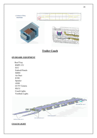
Underframe – Trailer Coach
Trailer Coach consits of the following Units:
l Cable Trays
l Traction Transformer
l Earth Return CT Box
l Auxilary Converter
l Isolation or Pantry Transformer
l Pneumatic Skids (ICF Scope)
l Water Equipment (ICF Scope)
28.
28
Non Driving TrailerCoach
NON DRIVING TRAILER COACH -ELECTRICAL CONTROL CABINET
NDTC ECC- MAJOR EQUIPMENT
29.
29
SHUNTING REMOTE
l DTC-CRWand NDTC-ECC of Train 18 have provision for shunting.
l 16 Car formation of Train- 18 houses 2 Shunting Panels.
l The dimensions of Shunting Panel are 145mm (L) x 100mm(W) x 220mm(H).
l Weight of each is approximately 2 kgs.
DTC,MC &NDTC
Underframe – Non Driving Trailer Coach
Non Drving Trailer Coach consits of the following Units:
l Cable Trays
30.
30
l Isolation orPantry Transformer
l Battery Charger
l Battery Box (ICF Scope)
l Pneumatic Skids (ICF Scope)
l Water Equipment (ICF Scope)
Driving Trailer Coach
NOSE CONE Equipment
Head Light
Front Viewing Camera
Flasher light
Headcode
CCTV camera
Cabin Light
Spot Light
31.
31
Marker Light
Tail Light
CabAC
Side Viewing Camera
Electrical Wiper
LRMS antenna
Wiper Wash Tank
Driver Seat
Driver Desk
DTC
32.
32
ON BO0ARD EQUIPMENT
RoofTray
RMPU CU
CRW
GCRW
Endwall Panels
SDDU
ICDU
Speaker
ANM
CCTV Camera
PECU
Coach Lights
Vestibule Lights
COACH ENDWALL PANELS
DRIVING TRAILER COACH - CAB REAR WALL PANEL
l Each DTC has one Cab Rear Wall panel.
l 16 Car formation of Train- 18 houses 2 CRW panels.
l The dimensions of CRW are 1100 mm (L) x 800 mm(W) x 1755 mm(H).
l Weight of each is approximately 450 kgs.
l CRW is located in the Driver cab
l The switches & MCBs on the CRW are accessed by the driver.
33.
33
GCRW- MAJOR EQUIPMENT
DTC- RMPU CONTROL PANEL
l DTC of Train 18 has one Roof Mounted Packaging Unit's Control Panel on board.
l 16 Car formation of Train- 18 houses 2 DTC-RMPU Control Panels.
l The dimensions of DTC - RMPU Panel are 700mm (L) x 200mm(W) x 1600mm(H).
l Weight of each is approximately 100 kgs.
l DTC RMPU panel is loacted at top right side of the coach when the coach is viewed
from top.
Underframe – Driving Trailer Coach
Driving Trailer Coach consits of the following Units:
l Cable Trays
l Isolation or Pantry Transformer
l Battery Charger
l Battery Box (ICF Scope)
l Pneumatic Skids (ICF Scope)
l Water Equipment (ICF Scope)
37
DESIGN FEATURES OFBOGIE FOR TRAIN 18
FIT FOR 160 KMPH OPERATION FACTORS:
· BOLSTERLESS DESIGN
· EFFECTIVE BRAKING SYSTEM
· SUITABLE SUSPENSION GEAR
· IMPROVED DRIVING GEAR SYSTEM
· OVERALL WEIGHT REDUCTION
· REDUCED UNSPRUNG MASS ANTIROLL BAR ARRANGEMENT
39
PARMARY SUSPENSION ASSEMBLY
WHEELAND AXLE ASSEMBLY
Ø WHEEL PRESS FITTING PRESSURE 79 T to 131 T
Ø DIFFERENCE IN DIA OF WHEELSET IN SAME AXLE MAX 0.5 mm
Ø DIFFERENCE IN DIA OF WHEELSET AXLE TO AXLE MAX 1.0 mm
Ø DIAMETER OF NEW WHEELSET Ø 952 mm
Ø DIAMETER OF CONDEMNED WHEELSET Ø 877 mm
46
Conventional Train
• Trainis hauled by a locomotive attached
at the end of train formatio
• Reversal requirements at terminals .
• Sluggish acceleration and deceleration.
• Inferior utilization of platform lengths as
Locomotive takes up some length.
• Requires higher capacity Mechanical
Coupler resulting in Jerks.
Train set
• Traction units or propulsion systems
are distributed over the train
formation
• No reversal requirement at terminals
• Quick acceleration/deceleration
• Better utilization of platform as
locomotive is not required
• Because of Distributed power Semi-
permanent coupler can be used –
which is jerk free .
47.
47
Types of Trainsets manufactured by ICF
• EMUs – mostly serving Metro cities . Most of them have been manufactured at ICF.
Current popular formation is 12 coaches (4 motor coaches) . Till date ICF has
manufactured 8000+
• MEMUs- 8 coach formation with 2 motor coaches .600+ manufactured till date
• DEMUs- Mostly running in hinterland-current formation is of 10 coaches having 2
power cars of 1600HP each – engines supplied by CUMMINS/CATERPILLAR.1951
manufactured till date.
• Kolkata Metro Train sets. 251 manufactured till date.8 coach formation (4 MOTOR
COACHES)
• SPARTs- accident relief trains with 3 coach formation.(2 power cars). 40+ sets
manufactured till date.
Train 18
• ICF has now embarked into manufacture World Class Train sets in India at half the
cost. ICF started the manufacture of Train set in the current year (2018) and this
project is code named as Train-18.
• Train-18 is a Semi-High Speed (160 Kmph) Multiple Unit Train set with quicker
acceleration and shall have contemporary passenger amenities.
• It will offer both comfort and pace to the passengers and in the long run, will replace
existing intercity express trains
• Initially all coaches will be Chair Car type for day travel.
• The most prominent feature will be that all coaches will be
• Inter-connected by Fully Sealed Gangways so that passengers can move from one
coach to other with ease.
• This is achieved by Shifting all Propulsion equipment from Onboard to Underslung.
• The Train set will be provided with Automatic Plug Type doors with retractable Foot
step which will open and close automatically at the stations.
48.
48
• To makethe travel more a joyful ride, all Coaches of the train will be provided with
On board Wi-fi, infotainment and GPS based Passenger Information System (PIS)
which will keep the passengers informed about the travel status
• The train will have plush interiors and diffused LED lighting. The Toilets of these
coaches will be fitted with Vacuum system, Zero Discharge Bio tanks and touch free
fittings.
• To keep the jerks and vibrations at bay, Train 2018 will be equipped with improved
centre couplers and new generation bogies with Fully suspended traction motors,
Pneumatic secondary suspension and anti-roll bar
• The Brake system will be Electro Pneumatic with brake discs mounted directly on
wheel discs, which will help to reduce the braking distance, so that full speed
potential of the Train Can be harnessed.
• The Train-2018 will have many modern features which will debut for the first time on
Indian Railways. Train 2018 will be a Landmark improvement in Passenger Travel.
• Train18 consists of Four Basic Units of Four Coach each. The configuration of End
Basic unit is as follows –
• DTC+MC+TC+MC
• The Configuration of middle Basic Unit is as follows –
• NDTC+MC+TC+MC
• DTC : Driving Trailer Coach MC : MOTOR COACH
• TC : Trailer Coach NDTC : Non-Driving Trailer Coach
50
• Motor Coachwill be equipped with Four Fully Suspended Traction Motors.
• Train-18 has 50% Powering, i.e. every alternate coach will be powered.
• All Propulsion equipment will be underslung, leaving the
on-board space for passengers.
• All coaches are chair-car type (Executive Class as Well as Second Class)
• All Coaches are Air-Conditioned including Driving Cab.
Features of Car body
• Stainless Steel Car Body
• The Car body will be equipped with Continuous Window Glasses for contemporary
modern look.
• The Driving coach will have Aero-dynamic Nose cone for reduced Air Drag and for
improved aesthetics.
• All coaches will be equipped with Automatic Plug Type Sliding doors with sliding
Foot Step
• All coaches are interconnected by Fully Sealed Gangways with flexible sidewalls.
• Exterior Fairings for the inter coach gangway giving a flushed look for the Train set.
• Side wall is 3 mm AISI – 409M Grade – In house Mfg
51.
51
• Carline ,Frame from Trade - (Suppliers Indra Industries /Pennar Industries )
• End wall from Trade (Suppliers Indra Industries /Pennar Industries )
• Roof 1.25 mm AISI – 304 Grade (Suppliers TI Industries)
• Underframe - bolster less design
• Coupler -Dellner Semi-permanent
• At ends – CBC Coupler
52.
52
The Bogie aredesigned with following Contemporary Features -
• Fit for 160 Kmph Operation.
• Fully Suspended Traction Motors - wherein the Traction Motor weight is not loaded
on to the wheel directly. This reduces the un-sprung mass, resulting in better ride
comfort.
• The bogie is bolster less design with Fabricated Y-type bogie frame. Air Springs in
Secondary suspension and Coil Spring with Control Arm.
• In Primary suspension for better stability. Vertical , lateral and YAW dampers for
improved comfort. Wheel mounted disc brake system for better reliability, space
utilization and less maintenance.
• Stabilizer (Anti -Roll Bar) mechanism for roll control of car body.
• Train 18 is an ambitious project taken up by ICF that will be designed and
manufactured by harnessing in house resources.
• Board has asked ICF to make 6 such train sets, out of which 2 shall be planned with
sleeper class coaches.
54
Wheel set
High Speeddouble Headed Intercity EXPRESS TRAIN MAXIMUM
OPERATING SPEED 160 KMPH
FORMATION :
TRACK GAUGE :
55.
55
High speed trainsdemand stable track structure and track maintenance within tight
tolerances
• Reason: heavy axle load sharing the same track causes faster deterioration of the track
geometry
• Rail wheel interaction generates additional vibrations due to short wave defects
• Use of soft, thick and resilient rubber pad and more resilient elastic fastenings ensure
more stable track geometry subjected to high vibrations caused by speedy
trains/heavy axle loads
High speed train generates vibrating forces at rail wheel contact level much different
than at lower speed.
• At high speed, SHORTER WAVES defects generates high frequency vibrations
which are detrimental for derailment forces
• Longitudinal wave defects cause Low frequency vibrations which are related with
passenger comfort.
• It is necessary to eliminate car motions of low frequencies (under 1 Hz)passengers
have feelings of nausea.
Short wave defects is with 0 – 25m and corresponding frequency is 0.5 to 120Hz. Related
with wheel interaction and managed at bogie level as it effects derailment forces , this can be
eliminated by high speed on track rail grinding( for rail) and through wheel scanning and
profiling(for wheel sets)
• Long wave defects caused due to ballast /formation settlement it is related with
vehicle-track interaction any forcing frequency 0.5 to 10 Hz is considered critical
for rolling stock
• Frequency 0.5 speed 160km/h f=v/d 0.5=(160*1000/3600) m/sec/d
f=44.44/d=88.88m say89m
Acceleration of wheel set ,Bogie and car body are to be ensured as per UIC 518.
56.
56
The stiffness ofthe wheelset is higher when passes over the concrete sleeper. The vibrations
induced by the slipper distance have a frequency of f=v/d v speed of the train, d is the
distance between two sleeper distance
At high speed ,
Equivalent conicity is an important parameter gives appropriate measure overall dynamic
stability of car body.
UIC 518 gives max value of equivalent of conicity 0.4 for 140km/h to 200km/h
Therefore suspension systems and damping parameters are to be enhanced for ensuring
maximum equivalent conicity of 0.4
The traverse bogie accelerations are to be considered below 4m/sec2 and traverse car body
accelerations to be below 1.5m/sec2 The standarddeviation car body acceleration must be
below 0.2m/sec2.
Train speed and power energy
E=mv2 e=powering energy is proportional to mass of the train and square of the train speed.
Ride comfort-
lateral and longitudinal accelerations of the vehicle’s centre of gravity
Stiffness of PRIMARY SUSPENSION and damping of secondary suspension has significant
effect in lateral acceleration
-+Stiffness of secondary suspension has significant effect in vertical acceleration of car
body
Ride comfort are evaluated as per UIC 513R and ISO 10056
The vehicle body acceleration in lateral and longitudinal directions are to be limited within
2.5 m/sec2 The acceptable ride index 2.5lateral and 2.75 vertical.
57.
57
Vehicle side
Ø properprimary and secondary suspension is fundamental
Ø Secondary lateral damping and primary longitudinal stiffness are the two most
sensitive parameters impacting the critical speed compared to other bogie components
Ø Air suspension in secondary suspension with Yaw dampers improves secondary
suspension system
EVOLUTION OF BOGIES IN INDIAN RAILWAYS
58.
58
Speed potential -
Theprocedure for certification of maximum permissible speed of the rolling stock
,either deciding the speed potential of any particular type of rolling stock or for
deciding the maximum permissible speed of a nominated train on a particular Route
has laid down in POLICY Circular No 6, issued under Railway Boards letter no
92/CEDO/SR/4/0 Pt dt 23.12.99
SALIENT DESIGN FEATURES of TRAIN 18 BOGIE
Ø SPEED POTENTIAL 160 KMPH
Ø BOLSTERLESS DESIGN
Ø AIR SPRING IN THE SECONDARY SUSPENSION
Ø COIL SPRING IN THE PRIMARY SUSPENSION
Ø WHEEL MOUNTED DISC BRAKE SYSTEM
Ø FULLY SUSPENDED TRACTION MOTOR SYSTEM
Ø LESS UNSPRUNG MASS – (FULLY SUSPENDED TRACTION MOTOR
SYSTEM )
Ø REGENERATIVE BRAKING SYSTEM
59.
59
VARIOUS PARTS OFTHE BOGIE
Adhesion
Ø Friction
Ø • Available to transfer tangential force
Ø • Between driving wheel and rail.
Ø • Pushes the train forward
Ø • Is called traction
Ø • Limited by coefficient of friction
Ø • If F > limit, wheel slip and rail burn
SLIP & CREEP
Ø Slip and creep are often used interchangeably.
60.
60
Ø Slip isthe additional speed that a wheel may have • Creep is the slip level divided by
the locomotive's speed
Ø For example, if the locomotive is moving at 12 KMPH and the wheel is turning at
13.2 KMPH, then there is 1.2 KMPH slip or 10% creep, therefore: 13.2 -12 = 1.2 slip
level 1.2 X 100 = 10% creep.
Adhesion is the ratio of drawbar force to locomotive weight.
The “dispatchable adhesion” is the overall adhesion rating - a measure of how much a
locomotive can pull. - to determine how many locomotives will be necessary to pull a
specific train over a specific section of railroad.
Adhesion Systems:
• Controlled-Creep – Radar Dependent,
• Back-up Wheel Slip - Non Radar,
• Starting (W/S) - Non Radar,
SLIP & CREEP
Wheel Slip Description Status Display Name Idle Mode This mode is active when the
locomotive is not in a loading Mode, i.e. Idle IDLE System Starting
This mode is active at low speeds, when there is not a reliable output from the radar.
The radar typically active above about 1 MPH. The starting system will normally be active up
to 1.5 MPH, and it may be active up to 3 MPH, under high adhesion conditions
Controlled
This is the creep mode known by most as “Super Series.” This mode is more formally
known as, “Controlled Creep” on AC locomotives.
In this mode the Radar is used as a ground speed reference, and the traction motor
wheel speed reference is controlled to allow the desired level of creep.
The speed reference dN is sent to the traction inverters and the inverters reduce the
torque output of the traction motors if the speed reference is exceeded.
61.
61
Backup System
The tractioninverters monitor the wheel speeds, primarily looking for high
accelerations, and reduce the motor torque accordingly.
The operation in the backup system is most obviously indicated by the, “N + dN”
signals being at 3600 rpm.
CONTROLLED-CREEP SYSTEM
• During Power, Speed-Control, dynamic brake, blended brake, opposite direction brake, and
rollback modes as long as all the proper feedback signals are present.
• involves computing wheel RPM limit (TxN+dN) signals and sending them to the
appropriate inverter controller.
The sign (value) of N+dN is positive when the locomotive is moving in the forward
direction and negative when moving in the reverse direction.
The magnitude of the N+dN should be greater when operating in “Power” and lower when
operating in “Dynamic Brake” (approximately 4% max.).
Dump Valve /Anti skid valve
The dump valve (Solenoid valve) works as an actuator. It is controlled by the
Microprocessor through DV. The valve (with 24 V DC supply) is operated to reduce the BC
pressure or to increase moment by moment in the event of wheel sliding and prevents flat tyre
62.
62
Railway Standard
REFURBISHING OFCTRB BEARING
As per Railway Board’s instruction,
(Railway Board’s letter No. 2004/M(C)/137/08 Dated 27.12.2006) bearings should be
refurbished by OEMs or manufacture after every 3 years or 12 Lakhs Kms of running,
whichever is earlier.
63.
63
If the bearingsare removed from axle prior to the above mentioned period, it should
also be refurbished.
Wheel sets and bogies
• Wheel sets-product requirements as per the EUROPEAN STANDARD
Ø EN 13260:2009+A1:2010(E)
document by technical committee CEN/TC 256 .
Ø EN13261-Railway applications-wheel sets and bogies -Axles-product requirements.
Ø EN13262 - Railway applications-wheel sets and bogies- WHEELS-product
requirements.
Motor coach wheel set for Train 18
Ø WHEEL AND AXLE COMPLETE assembly procedure as per specification
EN13260 ---supplier-BONATRANS.
Ø WHEEL PRESS FITTING PRESSURE:79T to 131T(755KN – 1290KN)
Ø WHEEL AND AXLE COMPLETE assembly procedure as per specification
EN13260 ---supplier-BONATRANS.
Ø WHEEL PRESS FITTING PRESSURE:79T to 131T(755KN – 1290KN)
64.
64
Wheel and axlefitting force
To Transmit forces and torques between the fitted elements, withstanding axial force of F
for 30 seconds without any displacement.
Ø Test shall be carried out at least 48 hours after fitting- for press-fitted wheels.
Ø The value of the force F in MN is F=4.10 dm
when the length of fitting L in mm lies .8dm < L < 1.1dm, dm is mean diameter in mm.
Characteristics of the press-fitting curve
Ø The fitting force shall start to increase before the wheel seat displacement on the
wheel hub reaches 30mm.
Ø The force shall increase continuously without falling outside the limit curve.
Ø A maximum decrease of 0.05MN (5T) over the last 25 mm of displacement.
Ø Range of final fitting force
0.85F < final fitting force < 1.45F fitting force: 79T to 131T( 755KN – 1290 KN)
where F in MN =4.10 dm {WHEEL SEAT- Ø222 V6 (+.31 to .33mm)}
Ø Interference for press fitting 0.0010dm ≤ j ≤ 0.0015dm
66
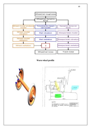
DETAILS OF AXLE& WHEEL OF THE TRAIN 18 WHEEL SET
Wheel set tread diameter variation
TRACK-TRAIN DYNAMICS AND ITS RELATION TO RAIL-WHEEL
INTERACTION.
Ø specific theoretical aspects of interaction between vehicle and track. - Vehicle
oscillations
Ø - Self-excited oscillations effect of wheel conicity, critical speed
Ø - Effect of cyclic track irregularities and resonance.
Ø - Effect of track or vehicle twist on wheel offloading and related factors
Ø - Lateral stability of track
67.
67
Adhesion
Tangential force
• Ifthe tangential stress reaches its maximum value according to
• Tangential stress ᴦmax =µ*σ a relative motion of the contact surface appears
called area of slip.
• µ = co-efficient of friction
• σ = Normal stress
• The tangential stress acts against the slip
Gyroscopic effect due to spinning of wheel set
• Spin is a rotation about vertical axis Z caused by wheel conicity.
• The relative spin Ѱ means angular velocity about z axis divided by speed v
• Ѱ=ώsinά /r ώ= angular velocity of wheel rolling
ά = angle of the contact surfaces
r = wheel radius
• Kalker’s method allows calculation of non linear forces and takes spin into account
68.
68
Factors increasing playbetween wheel rail
Apart from increased lateral oscillations
Ø Slack gauge
Ø Thin flange
Ø Excessive play between bearing and journal
Ø Lateral play between axle box and pedestal/bogie frame and lateral Between bogie
frame and bogie bolster
Ø Nadal’s did not specify the time required for gradual climbing of rail to complete.
Ø Research on the world railways has shown 0.05sec as the time duration
Ø On the Japanese National Railways -- Limiting value for Y/Q ratio are
Ø I) 0.8 –when duration t for which Y/Q ratio acts is 0.05sec or more.
Ø II)0.4/t–when duration t for which Y/Q ratio acts is less than 0.05sec .
Ø 0.05 sec time duration has been adopted by the AMERICAN ASSOCIATION OF
RAILROADS(AAR) for the certification new freight vehicles
Oscillation
70
Wheel and axlefitting force
TO Transmit forces and torques between the fitted
elements, withstanding axial force of F
for 30 seconds without any displacement.
Ø Test shall be carried out at least 48 hours after fitting- for press-fitted wheels.
Ø The value of the force F in MN is
F=4.10 dm
when the length of fitting L in mm lies
0.8dm < L < 1.1dm,
dm is mean diameter in mm
SECONDARY SUSPENSION
71.
71
CONSTRUCTION FEATURES OFAIR SPRING.
Ø Air springs are provided with air bellows made of rubber sufficiently reinforced with
several layers of fabric and provided with steel bead wires at the lips.
Ø The air bellow is fixed between a top plate and a bottom plate either by force fitting
the ends or by the use of screws.
Ø The air supply to the air spring is made through a spigot provided on the top plate. the
spigot fits inside the housing of the bogie bolster and is made air tight by the use of
two rubber `o` rings.
Ø The air spring is provided with an emergency spring to take up the load when the air
spring bellow fails for any reason.
Ø The emergency spring can either be provided within the air bellow or external to it.
Ø The air spring is also provided with an orifice plate at the air entry into the air spring
spigot to give the required damping effect when air flows from the air spring to the
reservoir and back.
WORKING OF AIR SPRING.
Ø Air springs are provided in the secondary suspension.
Ø The load is carried by the air spring bellow which is filled with compressed air.
Ø The air pressure is varied according to the load by a load sensing device called
leveling valve.
Ø The air spring is also provided with an emergency spring.
Ø When the air spring gets defective due to loss of air or any other reason , the
emergency spring will be able to carry the load under controlled vehicle speed.
PNUMATIC CONTROLE SYSTEM
Ø Air supply for the air spring is taken from the main reservoir pipe / feed pipe of the air
brake system.
Ø To cater to the needs of the air springs a 150 liter reservoir is provided which is
connected to the feed pipe through a centrifugal dirt collector, an isolating cock and
a check valve.
Ø Each bogie is provided with two air springs in the secondary suspension which are
connected to the pneumatic supply through a leveling valve.
72.
72
Functioning of airspring.
Ø leveling valve regulates the air pressure inside the Air spring according to the load
Ø The two air springs of a bogie are interconnected through a duplex check valve which
will allow air from one air spring to the other when the pressure difference of air in
the two air springs is equal to or greater than 1.5 bar.
Air spring arrangement with bogie bolster
WORKING OF LEVELLING VALVE
Ø The leveling valve controls the air pressure inside the air spring .
Ø It isolates the air spring from the pneumatic supply when there is no variation in the
payload.
Ø It is fixed to the bogie bolster and its horizontal lever operating the valve is connected
to the bogie frame through the installation lever.
Ø The installation lever is provided with ball and socket joints at both the ends to cater
for the relative movement of the bogie bolster with respect to the bogie frame in both
longitudinal and lateral directions.
Ø As the payload increases the bogie bolster comes down and the horizontal lever is
rotated upwards.
Ø This rotation operates the valve and more air is allowed into the air spring.
Ø The air pressure inside the air spring is increased, raising the bogie bolster till the
lever reaches the horizontal position again.
Ø When the payload decreases the bogie bolster goes up and the lever is rotated
downwards
Ø This rotation again operates the valve and air from the air spring is exhausted to the
atmosphere.
73.
73
Ø The airpressure inside the air spring is reduced, lowering the bogie bolster till the
lever reaches its horizontal position again.
Ø Thus it is seen that the level of the bolster is maintained irrespective of the payload.
Ø A dead band region is provided in the operation of the leveling valve so that it will not
operate during minor oscillation thus reducing the consumption of air.
CAUTION:
If the difference in pressure of the air in the air springs of the same bogie is more than setting
pressure of the duplex check valve, i.e. 1.5 bar, then air will be continuously escaping from
one air spring to the other through the duplex check valve.
Ø Tighten the installation lever lock nuts with the horizontal lever, so that the setting
will not be disturbed.
Ø Repeat the above procedure for the second bogie.
Ø Disconnect the pressure gauges and replace the drain plugs.
TEST FOR LEAKAGE
Ø Close the isolating cock in the pipeline connecting MR pipe with 150 litre reservoir.
Ø Connect the hose pipes on the underframe piping with the levelling valves of the
bogies as shown in the respective drawings.
Ø Connect pressure gauges to the drain plug locations of 20 litre reservoirs in the bogie.
Ø Connect the 150 litre reservoir in the underframe to the compressed air source of
pressure 7 kgf/sq. cm
Ø Provide 40mm packing in the gap between bolster & bogie frame.
Ø Allow air into the air springs to a value of 6 kgf/sq. cm in the pressure gauge by
adjusting the horizontal lever of the levelling valve and keep it in the same position.
Ø Test all pipe joints for leakages.
Ø Check the pressure gauge readings after one hour. the pressure drop should be with in
0.2 kgf/sq. cm.
Ø Release the air completely by dropping the horizontal lever.Remove the packing.
75
Train18 With 3Phase AC Propulsion
w Specification
w Rake Formation
w System layout
w System Details
· Performance Characteristics
· Brief Architecture-TCMS, Line and Traction Converter, Auxiliary converter.
Reference Specification
w RDSO/PE/SPEC/EMU/0096-2008 (Rev 4) along with ICF annexure no
ICF/EMU/0096-01-Rev-2
w MOM dated 3rd
June 2017 for additional requirement of Train18
w For development of Train18, additional performance requirement is improved
compared to normal EMU as % of motoring is increased.
Train18 important specification Details.
Particulars Details
Number of Coaches in Basic Unit 4 car per BU, DTC-MC-TC-MC (End
BU) NDTC-MC-TC-MC (Middle BU)
Train formation 16 coaches- 4 BU per Train
Maximum Service Speed 160 kmph
Average Acceleration from 0-40 kmph 0.8 m/sec2
Jerk Rate 0.7 m/sec3
76.
76
Basic Unit andRake Formation
w Train18 is 16 car train with 4 basic unit i.e. two number of end basic unit (DTC-MTC-
MC) and Two number of middle basic unit (NDTC-MC-TC-MC).
w All power components such as Line & Traction converters, Auxiliary converter, Air
Compressor, Battery box, Battery charger, Brake chopper resister are mounted under
the frame.
w Electronic is distributed across all the coaches.
End Basic Unit
Middle Basic Unit
System Block Diagram & Performance Characteristics
77.
77
Major Function doneby TCMS
w Interface with Driver Desk
· Pantograph Control
· VCB Control
w Traction Control
w Regenerative Brake Control and total brake calculation
w Brake Blending
Interface with RMPU control
Interface with Door control
Interface with Brake control
w Compressor control
w Parking Brake control
w Light Control
w Rollback Detection
w Load weighing calculation
w Air Bellow failure detection
w Vigilance control
w Cruise Control
w Neutral Section Control
w Event Recording
w All train level protection( ex:EOL,EBL,Cab Occupy)
Layout
Description Equipment
DTC Underframe-Compressor, Battery, Battery Charger
MC Underframe-Line and Traction converter, Motor, Brake
chopper resister.
TC Underframe-Transformer, Auxiliary converter
Roof-Pantograph, VCB
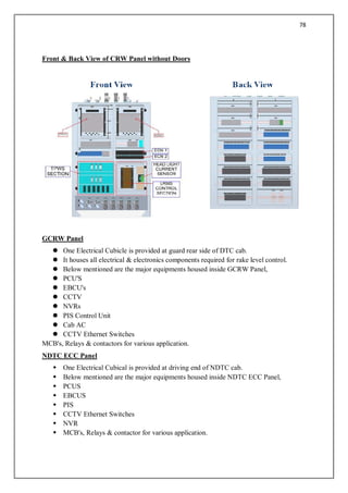
CRW Panel
l One Electrical Cubicle is provided at rear side of driver cab.
l It houses all electrical & electronics components required for rake level control.
l Below mentioned are the major equipments housed inside CRW Panel,
l CCU'S,
l ERMS,
l TPWS,
l ECN Switches,
l MCB's, Relays & contactors for various application.
78.
78
Front & BackView of CRW Panel without Doors
GCRW Panel
l One Electrical Cubicle is provided at guard rear side of DTC cab.
l It houses all electrical & electronics components required for rake level control.
l Below mentioned are the major equipments housed inside GCRW Panel,
l PCU'S
l EBCU's
l CCTV
l NVRs
l PIS Control Unit
l Cab AC
l CCTV Ethernet Switches
MCB's, Relays & contactors for various application.
NDTC ECC Panel
w One Electrical Cubical is provided at driving end of NDTC cab.
w Below mentioned are the major equipments housed inside NDTC ECC Panel,
w PCUS
w EBCUS
w PIS
w CCTV Ethernet Switches
w NVR
w MCB's, Relays & contactor for various application.
79.
79
END WALL Panels
lEnd Wall panels are located at Non Driving End of NDTC,TC,MC & DTC & Driving
End of NDTC,TC,MC.
l There are four types of EWP in each coach. They are EWP1,EWP2,EWP3 & EWP4.
l Below mentioned are the major equipments housed in EWP Panels,
l Terminal Blocks & IV Coupler Plates.
l Change Over Contactors.
l Wifi System, Monoblock Pump Controller (ICF Scope)
l MCB's for Passenger comforts like Charging socket MCB,Toilet MCB's,Pantry
MCB's etc.
View of EWP Panels in different type of Coaches
81
Welding Techniques inconstruction of LHB_Train 18
Session plan:
Shell construction & Features
Major assemblies
Side wall
End wall
Underframe
Roof
Body shell assembly
TRAIN 18 SALIENT FEATURES
— Stainless Steel Car Body
— LHB design as base design
— 16 Coach Chair Car Type Configuration
— 160 kmph speed . Test speed- 180 kmph
— Maximum Axle Load – 18 T
— Starting Acceleration – 0.8 m/sec2
— Deceleration – 1 m/sec2
82.
82
DIMENSIONAL COMPARISON
LHB ICF
LENGTHOVER BODY 23540 21770
LENGTH OVER BUFFER 24700 22280
WIDTH OVER BODY 3240 3245
INNER WIDTH 3120 3065
LONGER COACH - MORE PASSENGERS (LHB Vs CONVENTIONAL)
LHB CONVENTIONAL
ICF
— LENGTH OVER BODY 23.5 METERS 21.3 METERS
— MAX. DISTANCE 12.3 METERS 11.8 METERS
BETWEEN INNER WHEELS
NO OF PASSENGERS
SCZAC 78 67
FACZAC 56 46
FAC 22 24
ACCW 52 48
ACCN 64 72
84
LASER welding
— Laser- Light Amplification by Stimulated Emission of Radiation
— higher energy concentration
— fusion is achieved by directing a highly concentrated beam
— less heat-affected zone
— LASER gas - premixed CO2, CO, O2, He, Xe, N2
— Shielding gas N2
— No backing gas
— Shielding gas N2
— No backing gas
— Parent Material - X2CrNi12 (Both SS 409M)
— Thickness - 3 mm with 3 mm
LASER welding parameters
Parameter Tacking pass Welding Pass
Continuous power 1530 Watts 2290 Watts
Peak Power (Watts) 1530 Watts 2290 Watts
Pulse Energy (J) 0.302 Joules 0.302 Joules
Frequency (Hz) 5000 Hz 5000Hz
Duration (Milli
Seconds)
0.2 ms 0.2 ms
Travel Speed (mm /
min)
6000 mm / min 2500 mm / min
Shielding Gas
Classification &
Type
Liquid Nitrogen Liquid Nitrogen
Flow Rate 2 lpm 2 lpm
Purge Procedure Automatic Automatic
Working Distance 2100 mm 2100 mm
85.
85
Sidewall assembly Jigstage
— Sheet is placed first and Horizontal members & Pillars are placed and clamped
— TIG welding is done with pillars and stiffeners – interlocking joint
— Tack welding is done on sheet
TIG WELDING
TIG welding Parameters at Sidewall Jig
— Electrode : EW Th2 as per AWS 5.12
— Size of electrode : 2.4 mm
— Filler material : ER 308L ; 1.6 mm dia
— Shielding gas : 99.999% Argon
— Current : 80 -120 Amps
— Travel speed : 120 -190 mm/min
— Polarity - DCEN
Sidewall Robotic Spot welding
— Welding of sidewall sheet with pillars and stiffeners
— Pillars 2.5 mm , sheet 3 mm
— Both SS 409M
Parameter Setting
Weld current
(KA)
13.6 (+ / - 5%)
Squeeze time (Milli seconds) 300 (+ / - 5%)
Weld time (Milli seconds) 280 (+ / - 5%)
Hold time (Milli seconds) 300 (+ / - 5%)
86.
86
Electrode Force interms of Pr (Mpa) 0.62 (+ / - 5%)
Cooling water temp (deg C) 25
Cooling water flow rate (lpm) 10 Minimum
Endwall Assembly construction
— Made of SS 409M
— Consists of
— Endwall sheet
— Stiffeners
— Vestibule frame
Roof Assembly Jig
— TIG welding
— Over head
— Tack welding of roof
— Sheet and carline
— Electrode : EW Th2 as per AWS 5.12
— Size of electrode : 2.4 mm
— Filler material : ER 308L ; 1.6 mm dia
— Shielding gas : 99.999% Argon
— Current : 75 - 85 Amps
— Travel speed : 100 – 150 mm/min
— Flow rate : 10 lpm
87.
87
Roof Assembly –Robotic spot welding
Paraer setting
Weld current (KA) 9.8 (+ / - 5%)
Squeeze time (Milli seconds) 300 (+ / - 5%)
Weld time (Milli seconds) 210 (+ / - 5%)
Hold time (Milli seconds) 300 (+ / - 5%)
Electrode Force in terms of Pr (Mpa) 0.42 (+ / - 5%)
Cooling water temp (deg C) 23 – 28
Cooling water flow rate (lpm) 8.5 Minimum
Welding at Body Shell Assembly Jig
— MMAW
— IRS M44 or AWS 309L as AWS 5.4
— Electrode size 2.5
— 70 – 80 Amps
— Sidewall with roof,
Underframe and Endwall
full welded Inside the shell.
Outside tack welded
TIG Welding at Body Shell Assembly Jig
— Electrode : EW Th2 as per AWS 5.12
— Size of electrode : 2.4 mm
— Filler material : ER 309L ; 1.6 mm dia
— Shielding gas : 99.999% Argon
— Current : 75 - 85 Amps
— Travel speed : 100 – 150 mm/min
— Flow rate : 10 lpm