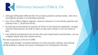
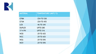
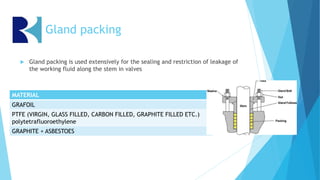
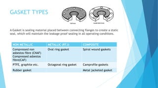
VALVE MATERIAL
OVERVIEW
-PART I
-Athira R Nair
Design Engineer
INTRODUCTION
 A valve is a device that regulates, directs or controls the flow, pressure, temperature
etc. of a fluid (gases, liquids, fluidized solids, or slurries) by opening, closing, or
partially obstructing various passageways.
 Valves construction consists of many distinct components of different materials
which are treated to make them desirable for respective fluid application.
OVERVIEW
 Materials specifications
 Classification of materials
 Material Properties
 Packing material
 Gasket Types
 Surface treatments
MATERIAlS
What are materials ?
 A material is a physical substance used to make things.
 Metals, ceramics, polymers & composites are some of the main
categories for materials.
How to define different materials ?
Classification of metals
Metals
Alloys
Ferrous Alloys
Carbon Steel
Stainless Steel
Non Ferrous
Alloys
Brass, Bronze,
Monel, Al-Br
etc.
Pure Metals
Aluminium,
Copper, Nickel
etc.
Material Properties
 Carbon (C): Iron is alloyed with carbon to make steel. Pure iron cannot be hardened or
strengthened by heat treatment but the addition of carbon enables a wide range of hardness
and strength.
 Manganese (Mn): Manganese is added to steel to improve hot working properties and increase
strength, toughness and hardenability.
 Chromium (Cr): Chromium is added to steel to increase resistance to oxidation. The corrosion
resistance is due to the formation of a self-repairing passive layer of Chromium Oxide on the
surface of the stainless steel.
 Nickel (Ni): Nickel greatly improves resistance to oxidation, carburization, nitriding, thermal
fatigue, corrosion along with increasing toughness, ductile & welding property along with this
it act as stabilizing agent.
 Molybdenum (Mo): Molybdenum, when added to chromium-nickel steels, improves resistance
to pitting and crevice corrosion especially in chlorides and sulphuric, phosphoric, and
hydrochloric acids containing environments.
 Nitrogen (N): Yield strength is greatly improved when nitrogen is added to stainless steels as is
resistance to pitting corrrosion.
 SiIicon (Si): Silicon is used as a deoxidising (killing) agent in the melting of steel and as a
result most steels contain a small percentage of Silicon.
 Low carbon steel
0.04% to 0.30% carbon content.
Properties: less ductile but harder and tougher than iron, grey colour, corrodes easily.
 Medium carbon steel
carbon range of 0.31% to 0.60%, and a manganese content ranging from .060% to 1.65%. This
product is stronger than low carbon steel, and it is more difficult to form, weld and cut.
Medium carbon steels are quite often hardened and tempered using heat treatment.
Properties: Harder and less ductile than mild steel, tough and have a high tensile strength.
 High Carbon steel
Commonly known as “carbon tool steel” it typically has a carbon range between 0.61% and
1.50%.
Properties: Very hard and brittle material.
Carbon steel
Carbon
steel
Elements % COMPOSITION
WCB WCC WC6 WC9
Carbon 0.30 0.25 0.05-0.20 0.05-0.18
Manganese 1.00 1.20 0.50-0.80 0.40-0.70
Phosphorous 0.04 0.04 0.04 0.04
Sulphur 0.045 0.045 0.045 0.045
Silicon 0.60 0.60 0.60 0.60
Nickel 0.50 0.50 0.50 0.50
Chromium 0.50 0.50 1.00-1.50 2.00-2.75
Molybdenum 0.20 0.20 0.45-0.65 0.90-1.20
Iron & other
elements
balance balance balance balance
Properties WCB WCC WC6 WC9
Tensile Strength (MPa) 485-655 485-655 485-655 485-655
Yield strength (MPa) 250 275 275 275
Elongation in 2” (%) 22 22 20 20
Reduction of area (%) 35 35 35 35
Stainless steel
Ferritic
Eg.: T400
series
(409,430)
16 – 18% of
Chromium
and less than
0.12% of
carbon.
Austenitic
Eg.: T300
series, T200
series
18% of
Chromium
and 8% of
nickel and
carbon is at
very low as
possible.
Martensitic
Eg.: T400
series
(410, 416)
12 – 14% of
Chromium
and 0.12 -
0.35% of
carbon.
Duplex
Eg.: T2205
22-25%
chromium
and 5%
nickel with
molybdenum
and
nitrogen.
Precipitation
hardening
Eg.: T17-4
Ferritic SS
 BCC crystal structure
 Magnetic and not heat treatable
 Type 430, 430Ti, 439, 441, 434, 436, 410L etc.
 Hard & less ductile
 Ferrite absorbs such a small amount of carbon
because of its BCC- one iron atom at each corner,
and one in the middle.
 Less widely-used due to their limited corrosion
resistance and average strength and hardness
 Fe-Cr-(Mo)
Austenitic SS
 FCC crystal structure
 Non Magnetic and not heat
treatable
 300 series - nickel based steel
 200 series - low nickel and high
nitrogen
 Soft & ductile
 Fe-Cr-Ni-(Mo)
Elements % COMPOSITION
CF3 CF8 CF3M CF8M 304L 304 316L 316 316Ti 321
Carbon 0.03 0.08 0.03 0.08 0.03 0.07 0.03 0.08 0.08 0.08
Manganese 1.50 1.50 1.50 1.50 2.00 2.00 2.00 2.00 2.00 2.00
Phosphorous 0.040 0.040 0.040 0.040 0.045 0.045 0.045 0.045 0.045 0.045
Sulphur 0.040 0.040 0.040 0.040 0.030 0.030 0.030 0.030 0.030 0.030
Silicon 2.00 2.00 1.50 1.50 0.75 0.75 0.75 0.75 0.75 0.75
Nickel 8.0-
12.0
8.0-
11.0
9.0-
13.0
9.0-
12.0
8.0-
12.0
8.0-
10.5
10.0-
14.0
10.0-
14.0
10.0-14.0 9.0-12.0
Chromium 17.0-
21.0
18.0-
21.0
17.0-
21.0
18.0-
21.0
17.5-
19.5
17.5-
19.5
16.0-
18.0
16.0-
18.0
16.0-18.0 17.0-19.0
Molybdenum 0.50 0.50 2.0-3.0 2.0-3.0 - - 2.0-3.0 2.0-3.0 2.0-3.0 -
Other
Elements
- - - - - - - - Ti 5 3 (C
+ N)
min, 0.70
max
Ti 5 3 (C
+ N)
min, 0.70
max
Iron Balanc
e
Balance Balance Balance Balance Balance Balance Balance Balance Balance
Difference between CF8M & 316
 Although ASTM grade CF8M and AISI 316 are both austenitic stainless steels, AISI 316 is
nonmagnetic because it is essentially austenite.
 Cast 316 or CF8M is slightly magnetic, however, because it is not entirely austenite and
contains from 5 – 20 percent ferrite.
 By reducing or eliminating the quantity of ferrite in the chemical composition, wrought
material manufacturers are able to make an alloy that is easier to roll into sheets or
bars.
 Cast material manufacturers do not have the same requirements and therefore, can use
a slightly harder alloy that contains ferrite.
Pros due to presence of ferrite in CF8M
- Higher yield strength, increased resistance to stress corrosion cracking, and cracking
during welding or casting, Less severe consequences of intergranular corrosion
Martensitic SS
 Body centered tetragonal
 Magnetic and heat treatable
 Type 410, 403, 410S, 431, 501, 502 etc.
 Hard
 Fe-Cr-C-(Ni-Mo) alloys
Duplex SS
 mixture of austenitic and ferritic grains in
their microstructure; hence they have a
“duplex” structure.
 Magnetic, Work hardenable alloy
 Type 2205, UR52N+, GR. 6A, 4A etc.
 They have high resistance to intergranular
corrosion. Even in chloride and sulphide
environments, Duplex stainless steel exhibit
very high resistance to stress corrosion
cracking.
 Fe-Cr-Ni-(Mo)-N
Precipitation hardening
(PH) SS
 Depending on chemical composition their
microstructure after final heat treatment is
austenitic, semi-austenitic or low carbon
martensitic.
 Type 17/4 PH, 17/7 PH, FV 520, etc.
 Heat treatable
 High strength-to-weight ratio.
 The semi austenitic grades are essentially
austenitic in the solution-annealed condition.
 The martensitic types are already martensitic
in the solution annealed condition and only
require precipitation hardening after
fabrication
 Fe-Cr-Ni-(Mo-Al-Cu-Nb)-N
Elements %Composition
410 410S 431 410L 2205 17/4 PH A995 4A A995 5A A995 6A C12A CA15
Carbon 0.08-
0.15
0.08 0.20 0.030 0.030 0.070 0.030 0.030 0.030 0.08-
0.12
0.15
Manganese 1.00 1.00 1.00 1.50 2.00 1.0 1.50 1.50 1.00 0.30-
0.60
1.00
Phosphoro
us
0.040 0.040 0.040 0.040 0.030 0.040 0.040 0.040 0.030 0.30 0.040
Sulphur 0.030 0.030 0.030 0.015 0.020 0.030 0.020 0.040 0.025 0.010 0.040
Silicon 1.00 1.00 1.00 1.00 1.00 1.0 1.00 1.00 1.00 0.20-
0.50
1.50
Nickel 0.75 0.60 1.25-2.50 0.30-
1.00
4.5-6.5 3.0-5.0 4.5-6.5 6.0-8.0 6.5-8.5 0.40 1.00
Chromium 11.5-
13.5
11.5-
13.5
15.0-17.0 10.5-
12.5
22.0-
23.0
15.0-
17.5
21.0-
23.5
24.0-
26.0
24.0-
26.0
8.0-9.5 11.5-
14.0
Molybdenu
m
- - - - 3.0-3.5 - 2.5-3.5 4.0-5.0 3.0-4.0 0.85-
1.05
0.50
Other
Elements
- - - Nitrogen
- 0.030
Nitrogen
– 0.14-
0.20
Copper –
3.0-5.0
Copper-
1.00
Nitrogen
- 0.10-
0.30
Nitrogen
Copper-
0.50-
1.00
- -
Iron Balance Balance Balance Balance Balance Balance Balance balance balance
MATERIAL TEMPERATURE LIMIT(°C)
CF8M -254 TO 538
CF3M -254 TO 455
LCB -46 TO 345
DUPLEX UPTO 280
17-4 PH UPTO 316
WCB -29 TO 425
WCC -29 TO 425
WC6 -29 TO 595
WC9 -29 TO 595
BOLTING AND NUT
MATERIALS
 Bolting material does not come in contact
with fluid, its material compatibility with
fluid is not important.
 The selection of bolt material is determined
based on service conditions and it is
wasteful to specify expensive alloys when
carbon steel material is entirely suitable. It
is important for bolting material to have
good tensile stress, hardness etc.
Elements %Composition
B7 B8 B7M B8M 2H 8 2HM
Carbon 0.37-0.49 0.08 0.37-0.49 0.08 0.40 0.08 0.40
Manganese 0.65-1.10 2.00 0.65-1.10 2.00 1.00 2.00 1.00
Phosphorous 0.035 0.045 0.035 0.045 0.040 0.045 0.040
Sulphur 0.040 0.030 0.040 0.030 0.050 0.030 0.050
Silicon 0.15-0.35 1.00 0.15-0.35 1.00 0.40 1.00 0.40
Nickel - 8.0-11.0 - 10.0-14.0 - 8.00-11.0 -
Chromium 0.75-1.20 18.0-20.0 0.75-1.20 16.0-18.0 - 18.0-20.0 -
Molybdenum 0.15-0.25 - 0.15-0.25 2.00-3.00 - - -
Hardness 321 HB, 35
HRC
223 HB, 96
HRB
235 HB, 99
HRB
223 HB, 96
HRB
248-327 HB,
24-35 HRC
126-300 HB,
32 HRC
159-235 HB,
84-99 HRC
Iron balance balance balance balance balance balance Balance
Gland packing
 Gland packing is used extensively for the sealing and restriction of leakage of
the working fluid along the stem in valves
MATERIAL
GRAFOIL
PTFE (VIRGIN, GLASS FILLED, CARBON FILLED, GRAPHITE FILLED ETC.)
polytetrafluoroethylene
GRAPHITE + ASBESTOES
GRAPHITE RING
GRAPHITE BRAIDED ROPE
PTFE RING PTFE BRAIDED ROPE
GASKET TYPES
A Gasket is sealing material placed between connecting flanges to create a static
seal, which will maintain the leakage proof sealing in all operating conditions.
NON METALLIC METALLIC (RTJ) COMPOSITE
Compressed non
asbestos fibre (CNAF)
Compressed asbestos
fibre(CAF)
Oval ring gasket Spiral wound gaskets
PTFE, graphite etc. Octagonal ring gasket Camprofile gaskets
Rubber gasket Metal jacketed gasket
RTJ gaskets
Spiral wound gaskets
Camprofile gaskets
NON-METALLIC GASKETS
Metal Jacketed gaskets
SURFACE
TREATMENTS
 Hardcoating
Eg.: chrome plating, electroless nickel plating.
 Hardfacing
Hardfacing is the deposition of thick coatings of hard, wear-resistant materials
on a worn or new component surface that is subject to wear in service. Thermal
spraying, spray-fuse and welding processes are generally used to apply the
hardfacing layer.
Eg.: stelliting
CHROME PLATING
 Chrome plating is the process of applying a layer of
chromium to a metal object. The first step in the industrial
chrome plating process is typically degreasing and cleaning
the surface the chromium will be applied to, which is known
as the substrate. This component may also need other types
of pre-treatment depending on its makeup. The plating
professional will then lower it into in an electrochemical
bath until the desired thickness is achieved.
 Hard chrome, often called industrial chrome, differs from
decorative chrome in that it is primarily designed to be
functional rather than aesthetic. Decorative chrome’s main
purpose is to enhance the visual appeal of an object by
applying a thin chrome coating. Hard chrome plating is much
more durable through a wide range of uses and
environments.
 Electroless nickel plating has a hardness of 63 HRC, whereas
hard chrome plating has a hardness between 68 HRC – 72
HRC.
NITRIDING
 Nitriding is a heat-treating process that diffuses nitrogen into the surface of a metal to
create a case-hardened surface. Case hardening, or surface hardening, is the process of
hardening the surface of a metal object while allowing the metal deeper underneath to
remain soft, thus forming a thin layer of harder metal at the surface. It is
predominantly used on steel. (450°C-650°C)
 improves the resistance to wear and the anti-friction qualities by increasing the surface
hardness along the valve stem, while retaining the inherent corrosion resistance of the
material at the valve seat.
 Gas nitriding, plasma nitriding, salt bath nitriding etc.
STELLITING
 Cobalt based alloys
 Wear resistant material
 Weld hard facing is used to deposit very thick (1 to 10mm) dense layers of wear
resistant material with high bond strength. Various welding techniques can be used,
including metal-inert gas (MIG), tungsten-inert gas (TIG), plasma transferred arc
(PTA), submerged arc (SAW) and manual metal arc (MMA). A very broad range of
coating materials can be applied.
 High pressure & high temperature environment
Stellite
Grade 6
Valve internals such as seats and
closure members can be at high risk of
erosion, abrasion, corrosion, galling
and damage from cavitation.
Hardfacing—applying harder material
to vulnerable parts can mitigate such
damage.
THANK
YOU

Valve material overview 1

  • 1.
  • 2.
    INTRODUCTION  A valveis a device that regulates, directs or controls the flow, pressure, temperature etc. of a fluid (gases, liquids, fluidized solids, or slurries) by opening, closing, or partially obstructing various passageways.  Valves construction consists of many distinct components of different materials which are treated to make them desirable for respective fluid application. OVERVIEW  Materials specifications  Classification of materials  Material Properties  Packing material  Gasket Types  Surface treatments
  • 3.
    MATERIAlS What are materials?  A material is a physical substance used to make things.  Metals, ceramics, polymers & composites are some of the main categories for materials. How to define different materials ?
  • 4.
    Classification of metals Metals Alloys FerrousAlloys Carbon Steel Stainless Steel Non Ferrous Alloys Brass, Bronze, Monel, Al-Br etc. Pure Metals Aluminium, Copper, Nickel etc.
  • 5.
    Material Properties  Carbon(C): Iron is alloyed with carbon to make steel. Pure iron cannot be hardened or strengthened by heat treatment but the addition of carbon enables a wide range of hardness and strength.  Manganese (Mn): Manganese is added to steel to improve hot working properties and increase strength, toughness and hardenability.  Chromium (Cr): Chromium is added to steel to increase resistance to oxidation. The corrosion resistance is due to the formation of a self-repairing passive layer of Chromium Oxide on the surface of the stainless steel.  Nickel (Ni): Nickel greatly improves resistance to oxidation, carburization, nitriding, thermal fatigue, corrosion along with increasing toughness, ductile & welding property along with this it act as stabilizing agent.  Molybdenum (Mo): Molybdenum, when added to chromium-nickel steels, improves resistance to pitting and crevice corrosion especially in chlorides and sulphuric, phosphoric, and hydrochloric acids containing environments.  Nitrogen (N): Yield strength is greatly improved when nitrogen is added to stainless steels as is resistance to pitting corrrosion.  SiIicon (Si): Silicon is used as a deoxidising (killing) agent in the melting of steel and as a result most steels contain a small percentage of Silicon.
  • 6.
     Low carbonsteel 0.04% to 0.30% carbon content. Properties: less ductile but harder and tougher than iron, grey colour, corrodes easily.  Medium carbon steel carbon range of 0.31% to 0.60%, and a manganese content ranging from .060% to 1.65%. This product is stronger than low carbon steel, and it is more difficult to form, weld and cut. Medium carbon steels are quite often hardened and tempered using heat treatment. Properties: Harder and less ductile than mild steel, tough and have a high tensile strength.  High Carbon steel Commonly known as “carbon tool steel” it typically has a carbon range between 0.61% and 1.50%. Properties: Very hard and brittle material. Carbon steel
  • 7.
    Carbon steel Elements % COMPOSITION WCBWCC WC6 WC9 Carbon 0.30 0.25 0.05-0.20 0.05-0.18 Manganese 1.00 1.20 0.50-0.80 0.40-0.70 Phosphorous 0.04 0.04 0.04 0.04 Sulphur 0.045 0.045 0.045 0.045 Silicon 0.60 0.60 0.60 0.60 Nickel 0.50 0.50 0.50 0.50 Chromium 0.50 0.50 1.00-1.50 2.00-2.75 Molybdenum 0.20 0.20 0.45-0.65 0.90-1.20 Iron & other elements balance balance balance balance Properties WCB WCC WC6 WC9 Tensile Strength (MPa) 485-655 485-655 485-655 485-655 Yield strength (MPa) 250 275 275 275 Elongation in 2” (%) 22 22 20 20 Reduction of area (%) 35 35 35 35
  • 8.
    Stainless steel Ferritic Eg.: T400 series (409,430) 16– 18% of Chromium and less than 0.12% of carbon. Austenitic Eg.: T300 series, T200 series 18% of Chromium and 8% of nickel and carbon is at very low as possible. Martensitic Eg.: T400 series (410, 416) 12 – 14% of Chromium and 0.12 - 0.35% of carbon. Duplex Eg.: T2205 22-25% chromium and 5% nickel with molybdenum and nitrogen. Precipitation hardening Eg.: T17-4
  • 9.
    Ferritic SS  BCCcrystal structure  Magnetic and not heat treatable  Type 430, 430Ti, 439, 441, 434, 436, 410L etc.  Hard & less ductile  Ferrite absorbs such a small amount of carbon because of its BCC- one iron atom at each corner, and one in the middle.  Less widely-used due to their limited corrosion resistance and average strength and hardness  Fe-Cr-(Mo)
  • 10.
    Austenitic SS  FCCcrystal structure  Non Magnetic and not heat treatable  300 series - nickel based steel  200 series - low nickel and high nitrogen  Soft & ductile  Fe-Cr-Ni-(Mo)
  • 11.
    Elements % COMPOSITION CF3CF8 CF3M CF8M 304L 304 316L 316 316Ti 321 Carbon 0.03 0.08 0.03 0.08 0.03 0.07 0.03 0.08 0.08 0.08 Manganese 1.50 1.50 1.50 1.50 2.00 2.00 2.00 2.00 2.00 2.00 Phosphorous 0.040 0.040 0.040 0.040 0.045 0.045 0.045 0.045 0.045 0.045 Sulphur 0.040 0.040 0.040 0.040 0.030 0.030 0.030 0.030 0.030 0.030 Silicon 2.00 2.00 1.50 1.50 0.75 0.75 0.75 0.75 0.75 0.75 Nickel 8.0- 12.0 8.0- 11.0 9.0- 13.0 9.0- 12.0 8.0- 12.0 8.0- 10.5 10.0- 14.0 10.0- 14.0 10.0-14.0 9.0-12.0 Chromium 17.0- 21.0 18.0- 21.0 17.0- 21.0 18.0- 21.0 17.5- 19.5 17.5- 19.5 16.0- 18.0 16.0- 18.0 16.0-18.0 17.0-19.0 Molybdenum 0.50 0.50 2.0-3.0 2.0-3.0 - - 2.0-3.0 2.0-3.0 2.0-3.0 - Other Elements - - - - - - - - Ti 5 3 (C + N) min, 0.70 max Ti 5 3 (C + N) min, 0.70 max Iron Balanc e Balance Balance Balance Balance Balance Balance Balance Balance Balance
  • 12.
    Difference between CF8M& 316  Although ASTM grade CF8M and AISI 316 are both austenitic stainless steels, AISI 316 is nonmagnetic because it is essentially austenite.  Cast 316 or CF8M is slightly magnetic, however, because it is not entirely austenite and contains from 5 – 20 percent ferrite.  By reducing or eliminating the quantity of ferrite in the chemical composition, wrought material manufacturers are able to make an alloy that is easier to roll into sheets or bars.  Cast material manufacturers do not have the same requirements and therefore, can use a slightly harder alloy that contains ferrite. Pros due to presence of ferrite in CF8M - Higher yield strength, increased resistance to stress corrosion cracking, and cracking during welding or casting, Less severe consequences of intergranular corrosion
  • 13.
    Martensitic SS  Bodycentered tetragonal  Magnetic and heat treatable  Type 410, 403, 410S, 431, 501, 502 etc.  Hard  Fe-Cr-C-(Ni-Mo) alloys
  • 14.
    Duplex SS  mixtureof austenitic and ferritic grains in their microstructure; hence they have a “duplex” structure.  Magnetic, Work hardenable alloy  Type 2205, UR52N+, GR. 6A, 4A etc.  They have high resistance to intergranular corrosion. Even in chloride and sulphide environments, Duplex stainless steel exhibit very high resistance to stress corrosion cracking.  Fe-Cr-Ni-(Mo)-N
  • 15.
    Precipitation hardening (PH) SS Depending on chemical composition their microstructure after final heat treatment is austenitic, semi-austenitic or low carbon martensitic.  Type 17/4 PH, 17/7 PH, FV 520, etc.  Heat treatable  High strength-to-weight ratio.  The semi austenitic grades are essentially austenitic in the solution-annealed condition.  The martensitic types are already martensitic in the solution annealed condition and only require precipitation hardening after fabrication  Fe-Cr-Ni-(Mo-Al-Cu-Nb)-N
  • 16.
    Elements %Composition 410 410S431 410L 2205 17/4 PH A995 4A A995 5A A995 6A C12A CA15 Carbon 0.08- 0.15 0.08 0.20 0.030 0.030 0.070 0.030 0.030 0.030 0.08- 0.12 0.15 Manganese 1.00 1.00 1.00 1.50 2.00 1.0 1.50 1.50 1.00 0.30- 0.60 1.00 Phosphoro us 0.040 0.040 0.040 0.040 0.030 0.040 0.040 0.040 0.030 0.30 0.040 Sulphur 0.030 0.030 0.030 0.015 0.020 0.030 0.020 0.040 0.025 0.010 0.040 Silicon 1.00 1.00 1.00 1.00 1.00 1.0 1.00 1.00 1.00 0.20- 0.50 1.50 Nickel 0.75 0.60 1.25-2.50 0.30- 1.00 4.5-6.5 3.0-5.0 4.5-6.5 6.0-8.0 6.5-8.5 0.40 1.00 Chromium 11.5- 13.5 11.5- 13.5 15.0-17.0 10.5- 12.5 22.0- 23.0 15.0- 17.5 21.0- 23.5 24.0- 26.0 24.0- 26.0 8.0-9.5 11.5- 14.0 Molybdenu m - - - - 3.0-3.5 - 2.5-3.5 4.0-5.0 3.0-4.0 0.85- 1.05 0.50 Other Elements - - - Nitrogen - 0.030 Nitrogen – 0.14- 0.20 Copper – 3.0-5.0 Copper- 1.00 Nitrogen - 0.10- 0.30 Nitrogen Copper- 0.50- 1.00 - - Iron Balance Balance Balance Balance Balance Balance Balance balance balance
  • 17.
    MATERIAL TEMPERATURE LIMIT(°C) CF8M-254 TO 538 CF3M -254 TO 455 LCB -46 TO 345 DUPLEX UPTO 280 17-4 PH UPTO 316 WCB -29 TO 425 WCC -29 TO 425 WC6 -29 TO 595 WC9 -29 TO 595
  • 18.
    BOLTING AND NUT MATERIALS Bolting material does not come in contact with fluid, its material compatibility with fluid is not important.  The selection of bolt material is determined based on service conditions and it is wasteful to specify expensive alloys when carbon steel material is entirely suitable. It is important for bolting material to have good tensile stress, hardness etc.
  • 19.
    Elements %Composition B7 B8B7M B8M 2H 8 2HM Carbon 0.37-0.49 0.08 0.37-0.49 0.08 0.40 0.08 0.40 Manganese 0.65-1.10 2.00 0.65-1.10 2.00 1.00 2.00 1.00 Phosphorous 0.035 0.045 0.035 0.045 0.040 0.045 0.040 Sulphur 0.040 0.030 0.040 0.030 0.050 0.030 0.050 Silicon 0.15-0.35 1.00 0.15-0.35 1.00 0.40 1.00 0.40 Nickel - 8.0-11.0 - 10.0-14.0 - 8.00-11.0 - Chromium 0.75-1.20 18.0-20.0 0.75-1.20 16.0-18.0 - 18.0-20.0 - Molybdenum 0.15-0.25 - 0.15-0.25 2.00-3.00 - - - Hardness 321 HB, 35 HRC 223 HB, 96 HRB 235 HB, 99 HRB 223 HB, 96 HRB 248-327 HB, 24-35 HRC 126-300 HB, 32 HRC 159-235 HB, 84-99 HRC Iron balance balance balance balance balance balance Balance
  • 20.
    Gland packing  Glandpacking is used extensively for the sealing and restriction of leakage of the working fluid along the stem in valves MATERIAL GRAFOIL PTFE (VIRGIN, GLASS FILLED, CARBON FILLED, GRAPHITE FILLED ETC.) polytetrafluoroethylene GRAPHITE + ASBESTOES
  • 21.
    GRAPHITE RING GRAPHITE BRAIDEDROPE PTFE RING PTFE BRAIDED ROPE
  • 22.
    GASKET TYPES A Gasketis sealing material placed between connecting flanges to create a static seal, which will maintain the leakage proof sealing in all operating conditions. NON METALLIC METALLIC (RTJ) COMPOSITE Compressed non asbestos fibre (CNAF) Compressed asbestos fibre(CAF) Oval ring gasket Spiral wound gaskets PTFE, graphite etc. Octagonal ring gasket Camprofile gaskets Rubber gasket Metal jacketed gasket
  • 23.
    RTJ gaskets Spiral woundgaskets Camprofile gaskets NON-METALLIC GASKETS Metal Jacketed gaskets
  • 24.
    SURFACE TREATMENTS  Hardcoating Eg.: chromeplating, electroless nickel plating.  Hardfacing Hardfacing is the deposition of thick coatings of hard, wear-resistant materials on a worn or new component surface that is subject to wear in service. Thermal spraying, spray-fuse and welding processes are generally used to apply the hardfacing layer. Eg.: stelliting
  • 25.
    CHROME PLATING  Chromeplating is the process of applying a layer of chromium to a metal object. The first step in the industrial chrome plating process is typically degreasing and cleaning the surface the chromium will be applied to, which is known as the substrate. This component may also need other types of pre-treatment depending on its makeup. The plating professional will then lower it into in an electrochemical bath until the desired thickness is achieved.  Hard chrome, often called industrial chrome, differs from decorative chrome in that it is primarily designed to be functional rather than aesthetic. Decorative chrome’s main purpose is to enhance the visual appeal of an object by applying a thin chrome coating. Hard chrome plating is much more durable through a wide range of uses and environments.  Electroless nickel plating has a hardness of 63 HRC, whereas hard chrome plating has a hardness between 68 HRC – 72 HRC.
  • 26.
    NITRIDING  Nitriding isa heat-treating process that diffuses nitrogen into the surface of a metal to create a case-hardened surface. Case hardening, or surface hardening, is the process of hardening the surface of a metal object while allowing the metal deeper underneath to remain soft, thus forming a thin layer of harder metal at the surface. It is predominantly used on steel. (450°C-650°C)  improves the resistance to wear and the anti-friction qualities by increasing the surface hardness along the valve stem, while retaining the inherent corrosion resistance of the material at the valve seat.  Gas nitriding, plasma nitriding, salt bath nitriding etc.
  • 27.
    STELLITING  Cobalt basedalloys  Wear resistant material  Weld hard facing is used to deposit very thick (1 to 10mm) dense layers of wear resistant material with high bond strength. Various welding techniques can be used, including metal-inert gas (MIG), tungsten-inert gas (TIG), plasma transferred arc (PTA), submerged arc (SAW) and manual metal arc (MMA). A very broad range of coating materials can be applied.  High pressure & high temperature environment
  • 28.
    Stellite Grade 6 Valve internalssuch as seats and closure members can be at high risk of erosion, abrasion, corrosion, galling and damage from cavitation. Hardfacing—applying harder material to vulnerable parts can mitigate such damage.
  • 29.