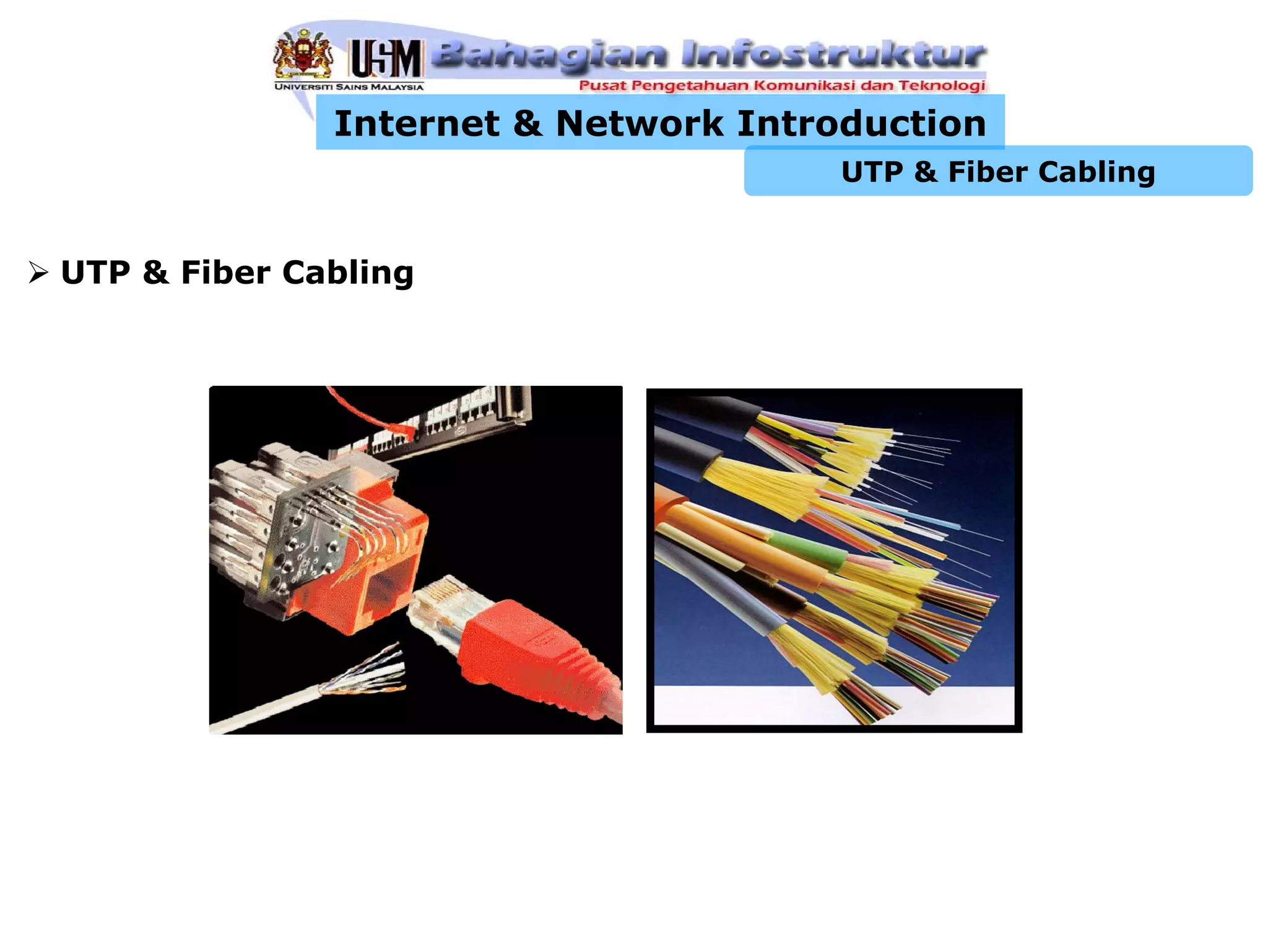
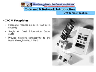
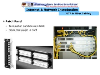
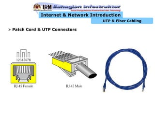
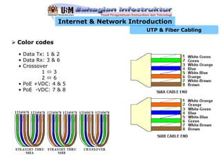
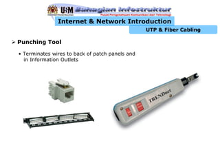
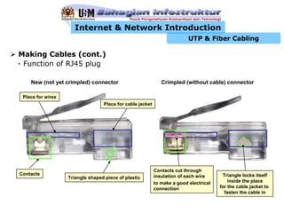
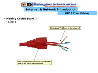
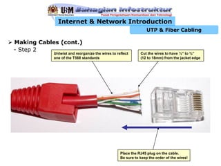
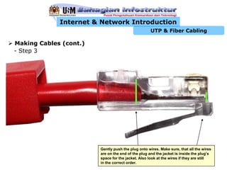
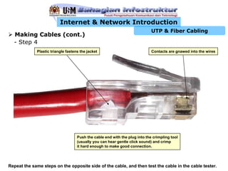
1) Structured cabling uses UTP cable with RJ45 connectors running between faceplates, patch panels, and patch cords to connect devices.
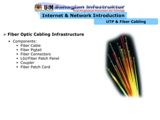
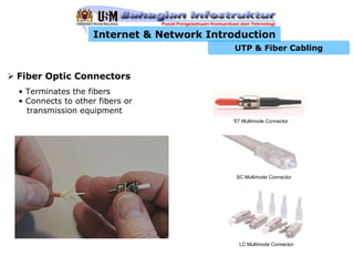
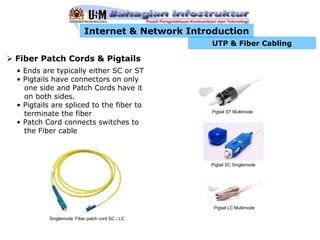
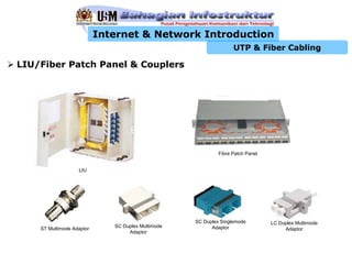
2) Fiber optic cabling uses glass fiber and connectors like SC, ST or LC run between fiber patch panels and fiber patch cords.
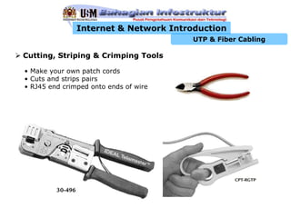
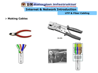
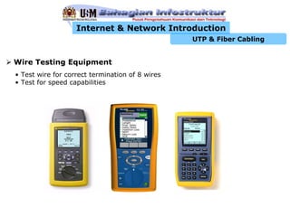
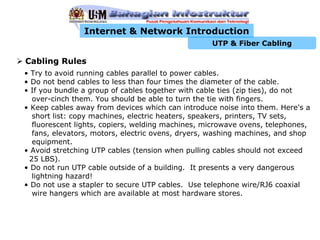
3) Proper cable installation, testing and maintenance following cabling rules ensures a high performance network infrastructure.


![Tweet Book #pisablog12 [si...parte 2]](https://cdn.slidesharecdn.com/ss_thumbnails/tweet-book-pisablog12-2-120630083004-phpapp01-thumbnail.jpg?width=640&height=640&fit=bounds)


