This document discusses general solutions for calculating stresses in beams with arbitrary cross-sections subjected to unsymmetrical bending. It presents equations to determine the neutral axis angle and stresses as a function of the bending moments and cross-sectional properties. As an example, it provides the solution for an L-shaped beam subjected to an inclined force, calculating the centroid and determining the maximum tensile and compressive stresses.
Learn Online Courses of Subject Engineering Mechanics of First Year Engineering. Clear the Concepts of Engineering Mechanics Through Video Lectures and PDF Notes. Visit us: https://ekeeda.com/streamdetails/subject/Engineering-Mechanics
Fem /certified fixed orthodontic courses by Indian dental academy Indian dental academy
The Indian Dental Academy is the Leader in continuing dental education , training dentists in all aspects of dentistry and offering a wide range of dental certified courses in different formats.
Indian dental academy provides dental crown & Bridge,rotary endodontics,fixed orthodontics,
Dental implants courses.for details pls visit www.indiandentalacademy.com ,or call
0091-9248678078
Bending Stresses are important in the design of beams from strength point of view. The present source gives an idea on theory and problems in bending stresses.
Bending Stresses are important in the design of beams from strength point of view. The present source gives an idea on theory and problems in bending stresses.
Welcome to the Program Your Destiny course. In this course, we will be learning the technology of personal transformation, neuroassociative conditioning (NAC) as pioneered by Tony Robbins. NAC is used to deprogram negative neuroassociations that are causing approach avoidance and instead reprogram yourself with positive neuroassociations that lead to being approach automatic. In doing so, you change your destiny, moving towards unlocking the hypersocial self within, the true self free from fear and operating from a place of personal power and love.
Program Your Destiny eBook - Destiny University.pdf
Unsymmetrical bending
1. General Solutions for Unsymmetrical Bending of Beams with Arbitrary Cross Sections
y
M My
y
dA
z
θ
α yθ
z x z
Mz
P
P
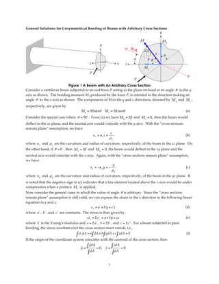
Figure 1 A Beam with An Arbitrary Cross Section
Consider a cantilever beam subjected to an end force P acting in the plane inclined at an angle θ to the y-‐‑
axis as shown. The bending moment M, produced by the force P, is oriented in the direction making an
angle θ to the z-‐‑axis as shown. The components of M in the y and z-‐‑directions, denoted by M y and M z ,
respectively, are given by
My = M sinθ Mz = M cosθ (a)
Consider the special case where θ = 90 . From (a) we have My = M and Mz = 0 , then the beam would
deflect in the xz plane, and the neutral axis would coincide with the y-‐‑aixs. With the “cross sections
remain plane” assumption, we have
z
ε x = κ z z = (b)
ρz
where κ z and ρ z are the curvature and radius of curvature, respectively, of the beam in the xz plane. On
the other hand, if θ = 0 , then Mz = M and My = 0 , the beam would deflect in the xy plane and the
neutral axis would coincide with the z-‐‑aixs. Again, with the “cross sections remain plane” assumption,
we have
y
ε x = −κ y y = − (c)
ρy
where κ y and ρ y are the curvature and radius of curvature, respectively, of the beam in the yz plane. It
is noted that the negative sign in (c) indicates that a line element located above the z-‐‑axis would be under
compression when a positive M z is applied.
Now consider the general cases in which the value of angle θ is arbitrary. Since the “cross sections
remain plane” assumption is still valid, we can express the strain in the x direction in the following linear
equation in y and z:
ε x = aʹ′ + bʹ′y + cʹ′z (d)
where aʹ′ , bʹ′ , and cʹ′ are constants. The stress is then given by
σ x = Eε x = a + by + cz (e)
where E is the Young’s modulus and a = Eaʹ′ , b = Ebʹ′ , and c = Ec ʹ′ . For a beam subjected to pure
bending, the stress resultant over the cross section must vanish, i.e.,
∫ σ x dA = a ∫ dA + b∫ ydA + c ∫ zdA = 0 (f)
If the origin of the coordinate system coincides with the centroid of the cross section, then
y=
∫ ydA = 0, z=
∫ zdA = 0
∫ dA ∫ dA
1
2. Consequently, a = 0 and (e) becomes
σ x = by + cz (g)
The resultant moments on the cross section are given by
M y = ∫ σ x zdA = b ∫ yzdA + c ∫ z 2 dA = bI yz + cI y (h)
M z = − ∫ σ x ydA = −b ∫ y 2 dA − c ∫ yzdA = −bI z − cI yz (i)
where
I y = ∫ z 2 dA , I z = ∫ y 2 dA , I yz = ∫ yzdA
are the moments of inertia of the cross section. Solving (h) and (i) simultaneously yields
M z I y + M y I yz M y I z + M z I yz
b=− 2
, c= 2
(j)
I y I z − I yz I y I z − I yz
Substituting (j) into (g) gives
M z I y + M y I yz M y I z + M z I yz
σx = − 2
y+ 2
z (k)
IyIz − I yz I y I z − I yz
The neutral axis, by definition, is the line along which stress vanishes. Thus, by setting σ x = 0 in (k), we
have
y M y I z + M z I yz I yz + I z tan θ I z + I yz cot θ
tan α = = = = (l)
z M z I y + M y I yz I y + I yz tan θ I yz + I y cot θ
in which α (see Fig. 1) is the angle measured clockwise from the z-‐‑axis to the neutral axis, and
My M
tan θ = , or cotθ = z (m)
Mz My
Combining (k) and (m) and eliminating M y , we obtain the following simplified equation in terms of M z
and angle α for calculating the stresses:
Mz (y − z tanα )
σx = − (n)
I z − I yz tan α
If the y-‐‑ and z-‐‑axes coincide with the principal axes, then I yz = 0 and (l) reduces to
Iz
tan α = tan θ
Iy
which is the same as (6-‐‑19) in the textbook. Furthermore, if θ = 0 (i.e., Mz = M and My = 0 ), then α = 0
and (n) becomes
Mz y
σx = −
Iz
Example:
A 5.0 m long simply-‐‑supported beam is subjected to a force P = 4 kN at a point that is 2.0 m away from
the far end, as shown in the figure. The dimensions of the L-‐‑shaped cross section are shown in the figure.
If the force P is applied in an inclined plane making a 10° angle with the y-‐‑axis, determine the locations
and magnitudes of the maximum tensile and compressive stresses in the beam.
Solution:
(a) Locate the centroid of the cross section (in terms of distances y 0 and z0 measured from point A):
(120 × 10)(60) + (70 × 10)(5 )
y0 = = 39.74 mm
(120 × 10) + (70 × 10)
(120 × 10)(5) + (70 × 10)(45)
z0 = = 19.74 mm
(120 × 10) + (70 × 10)
2
3. P y
10
B
10 mm
2 m P 120 mm
α
z M
10
10 mm
3 m y0
A
z0
80 mm
Figure 2 Umsymmetric Bending of A Simply-Supported Beam
(b) Determine the moments of inertia:
(120)(10)3 (10)(70)3
Iy = + (120)(10)(19.74 − 5)2 + + (10)(70)(45 − 19.74 )2 = 1.003 × 106 mm 4
12 12
(10)(120)3 (70)(10)3
Iz = + (10)(120)(60 − 39.74 )2 + + (70)(10)(39.74 − 5)2 = 2.783 × 106 mm 4
12 12
I yz = (10)(1120)(60 − 39.74 )(19.74 − 5) + (70)(10)(5 − 39.74)(19.74 − 45) = 0.973 × 106 mm 4
(c) Determine the neutral axis:
Since θ = −10 (i.e., positive θ measured clockwise from the z axis), we have, from (l),
I yz + I z tan θ 0.973 × 10 6 + 2.783 × 10 6 × tan − 10( )
tan α = = = 0.580
I y + I yz tan θ 1.003 × 10 6 + 0.973 × 10 6 × tan − 10( )
The neutral axis thus is oriented at the angle
α = tan−1 (0.580) = 0.526 rad = 30.12
(d) Determine the maximum stresses in the beam:
The maximum bending moment along the beam occurs at the point where the load P is applied, i.e.,
Pab (4.0 )(2.0)(3.0)
Mmax = = = 4.8 kN ⋅ m = 4.8 × 10⁶ N ⋅ mm
L 5.0
where L = 5.0 m , a = 2.0 m , and b = 3.0 m . The y and z components of this moment are
My = Mmax sin θ = −0.834 × 10⁶ N ⋅ mm
Mz = Mmax cos θ = 4.727 × 10⁶ N ⋅ mm
From Fig.2 it is easy to see that the two locations denoted by A and B are the farthest from the neutral
axis, hence would experience the highest tensile or compressive stresses. The y and z coordinates of
those two points are A(−39.74 , 19.74 ) and B(80.26 , 9.74 ) , respectively. The maximum tensile stress,
occurs at point A, is given by
3
4. M z (y − z tan α )
σx = −
I z − I yz tan α
=−
(4.727 × 10 )[− 39.74 − (19.74)tan(30.12 )]
6
2.783 × 10 − (0.973 × 10 )tan(30.12 )
6 6
N
= 109.0 × 106
= 109.0 MPa
mm 2
The maximum compressive stress, occurs at point B, is given by
M (y − z tan α )
σx = − z
I z − I yz tan α
=−
(4.727 × 10 )[80.26 − (9.74)tan(30.12 )]
6
2.783 × 10 − (0.973 × 10 )tan(30.12 )
6 6
N
= −159.0 × 106 = −159.0 MPa
mm 2
(e) Solve the same problem by using the method outlined in Section 6-‐‑5 of the textbook:
The principal axes are denoted as Y and Z, respectively, in Fig.3. The directions of the principal axes
and the principal moments of inertia of the cross section can be obtained by using (A-‐‑11) and (A-‐‑12)
in the textbook. Let β be the angle between the principal axis and y-‐‑axis (see Fig.2), then from (A-‐‑11)
2 I yz 2(0.973 × 10⁶ )
tan 2θ p = tan 2 β = − =− = 1.093
Iy − Iz 1.003 × 10 6 − 2.783 × 10 6
and
1
β = tan −1 (1.093) = 23.8
2
The principal moments of inertia can be obtained by substituting the value of β in (A-‐‑10), or using
(A-‐‑12):
P y
Y
10
B
β
π
−β
2
ψ α
z M
10
β
Z
A
Figure 3 Neutral Axis and Principal Axes
4
5. 2
Iy + Iz ⎛ I y − I z ⎞ 2 6 4 6 4
I max,min = ⎜ 2 ⎟ + I yz = 3.212 × 10 mm , 0.574 × 10 mm ,
± ⎜ ⎟
2 ⎝ ⎠
Thus,
IY = 0.574 × 106 mm 4 I Z = 3.212 × 106 mm 4
The components of M in the Y and Z directions, respectively, are now given by
MY = M sin(β − 10 ) = 1.143 × 10⁶ N ⋅ mm
MZ = M cos(β − 10 ) = 4.662 × 10⁶ N ⋅ mm
The angle ψ , which determines the orientation of neutral axis and is measured clockwise from the Z-‐‑
axis as shown in Fig.3, is given by
Y M I I
(
tan ψ = = Y Z = Z tan β − 10 = 1.374
Z MZ I Y I Y
)
from which
ψ = tan −1 (1.374 ) = 53.9
It can be seen from Fig.3 that
α = ψ − β = 30.1
which matches the value obtained previously. With respect to the principal axes, the stresses are
given by
M Z M Y
σ x = Y − Z
IY IZ
At point A, the coordinates are
YA = y A cos β + z A sin β = −28.4 mm
Z A = − y A sin β + z A cos β = 34.1 mm
and the stress is given by
MY Z MZY (1.143 × 10 3 )(34.1) (4.662 × 10 3 )(− 28.4 )
σx = − = − = 109.0 MPa
IY IZ 0.574 × 10⁶ 3.212 × 10⁶
At point B, the coordinates are
YB = y B cos β + zB sin β = 77.4 mm
ZB = − y B sin β + zB cos β = −23.5 mm
and the stress is given by
M Z M Y (1.143 × 10 3 )(− 23.5 ) (4.662 × 10 3 )(77.4 )
σx = Y − Z = − = −159.0 MPa
IY IZ 0.574 × 10⁶ 3.212 × 10⁶
5