Download to read offline
![COMP 557 lecture 4 Sept. 11, 2008
Homogeneous coordinates
Last class we have represented a 3D point (x, y, z) as a point (x, y, z, 1) in ℜ4 . We now generalize
this by representing (x, y, z) as any 4D vector of the form (wx, wy, wz, w) where w = 0. Note that
the set of points
{ (wx, wy, wz, w) : w = 0 }
is a line in ℜ4 which passes through the origin and the point (x, y, z, 1) in ℜ4 . [ASIDE: note we are
associating each point in ℜ3 with a line in ℜ4 , in particular, a line that passes through the origin.]
Is this generalization consistent with the 4 × 4 rotation, translation, and scaling matrices which
we introduced last class. Yes, it does, since for any q = (x, y, z, 1),
w(Mq) ≡ M(wq),
that is, multiplying each component of the vector q by w and transforming by M yields the same
vector as transforming q by M and then muliplying each component of M q by w. But multiplying
each component of a 4D vector by w doesn’t change the 3D point that is represented.
But what do we gain in identifying (x, y, z, 1) with (wx, wy, wz, w) ? Answer: alot. For example,
consider the projection mapping above. We re-write our projected points as follows:
x y
(f , f , f, 1) ≡ (xf, yf, f z, z).
z z
This allows us to represent the projection transformation by a 4 × 4 matrix, i.e. :
fx f 0 0 0 x
fy 0 f 0 0 y
fz = 0 0 f 0 z
z 0 0 1 0 1
Several observations can be made. First, since we are now treating all 4D points (wx, wy, wz, w)
as representing the same 3D point, we can multiply any 4 × 4 transformation matrix by a constant,
without changing the transformation that is carried out by the matrix. The above matrix can be
divided by the constant f and written instead as:
1 0 0 0
0 1 0 0
0 0 1 0
1
0 0 f 0
This matrix, like the one above, projects the 3D scene onto the plane z = f , with center of projection
being the origin (0, 0, 0).
A second observation is that, whereas the 4 × 4 translation, rotation, and scaling matrices were
invertible (and hence of rank 4), the projection matrix is clearly not invertible. It is of rank 3 since
the third and fourth rows are linearly dependent i.e. they differ only by a multiplicative constant.
A third observation is that there is nothing magic about the z = f projection plane. We can
easily define projections onto other planes. For example, the following matrix projects onto the
2](https://image.slidesharecdn.com/cg-110930070607-phpapp02/75/Cg-2-2048.jpg)


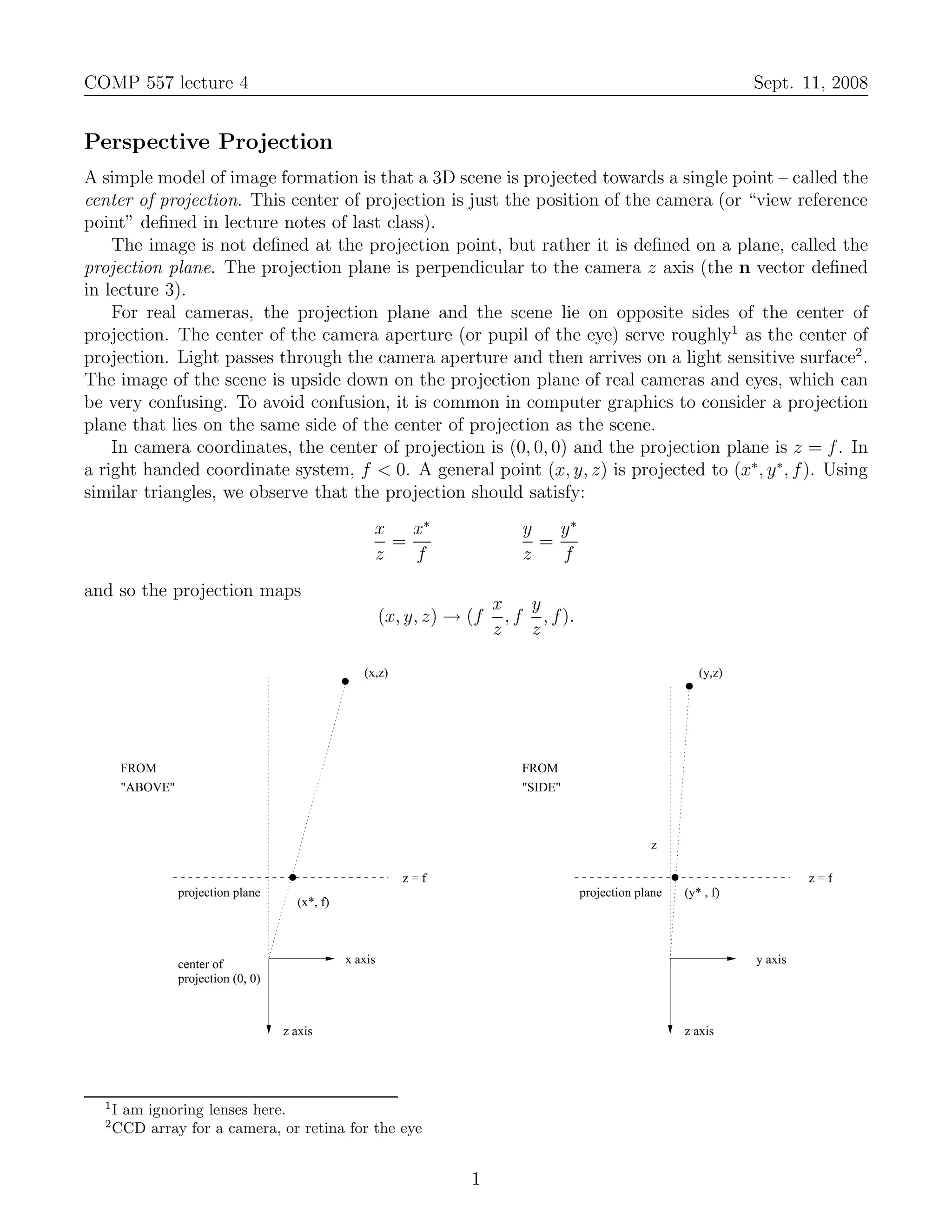
1) The document discusses perspective projection, which models image formation by projecting a 3D scene onto a 2D projection plane from a single center of projection, analogous to a camera. 2) It introduces homogeneous coordinates to represent 3D points as 4D vectors, allowing perspective transformations to be represented by 4x4 matrices. 3) Two examples of perspective projections are shown - onto the plane z=f, and onto z=0 with the center of projection at (0,0,f). 4x4 matrices representing these transformations are derived.


![[shaderx5] 4.2 Multisampling Extension for Gradient Shadow Maps](https://cdn.slidesharecdn.com/ss_thumbnails/shaderx542-100523142440-phpapp02-thumbnail.jpg?width=640&height=640&fit=bounds)


![Chapter4_Initiation_of_Sediment_Motion_v2[1].pptx](https://cdn.slidesharecdn.com/ss_thumbnails/chapter4initiationofsedimentmotionv21-251208223747-f94ef163-thumbnail.jpg?width=640&height=640&fit=bounds)


