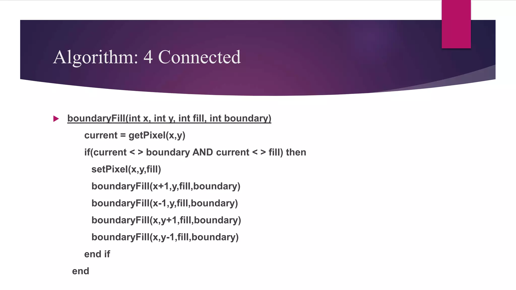
The document discusses different techniques for filling polygons, including boundary fill, flood fill, and scan-line fill methods. It explains that boundary fill and flood fill work by recursively filling neighboring pixels of the same color until reaching the polygon boundary. Scan-line fill works by drawing pixels between edge intersections on each scan line from top to bottom of the polygon. Special cases like handling vertices and updating edge positions are important to the scan-line fill algorithm.
The Lian-Barsky algorithm is a line clipping algorithm. This algorithm is more efficient than Cohen–Sutherland line clipping algorithm and can be extended to 3-Dimensional clipping. This algorithm is considered to be the faster parametric line-clipping algorithm. The following concepts are used in this clipping:
The parametric equation of the line.
The inequalities describing the range of the clipping window which is used to determine the intersections between the line and the clip window.
he capability that show some part of object internal a specify window is called windowing and a rectangular region in a world coordinate system is called window. ... Points and lines which are outside the window are "cut off" from view. This process of "cutting off" parts of the image of the world is called Clipping.
Sutherland hodgman polygon clipping algorithmTawfiq Ahmed
Sutherland Hodgman polygon clipping algorithm is a very simple clipping algorithm to understand. I hope my slide will help you guys.
-Thanks
Tawfiq Ahmed
Final project report on grocery store management system..pdfKamal Acharya
In today’s fast-changing business environment, it’s extremely important to be able to respond to client needs in the most effective and timely manner. If your customers wish to see your business online and have instant access to your products or services.
Online Grocery Store is an e-commerce website, which retails various grocery products. This project allows viewing various products available enables registered users to purchase desired products instantly using Paytm, UPI payment processor (Instant Pay) and also can place order by using Cash on Delivery (Pay Later) option. This project provides an easy access to Administrators and Managers to view orders placed using Pay Later and Instant Pay options.
In order to develop an e-commerce website, a number of Technologies must be studied and understood. These include multi-tiered architecture, server and client-side scripting techniques, implementation technologies, programming language (such as PHP, HTML, CSS, JavaScript) and MySQL relational databases. This is a project with the objective to develop a basic website where a consumer is provided with a shopping cart website and also to know about the technologies used to develop such a website.
This document will discuss each of the underlying technologies to create and implement an e- commerce website.
Explore the innovative world of trenchless pipe repair with our comprehensive guide, "The Benefits and Techniques of Trenchless Pipe Repair." This document delves into the modern methods of repairing underground pipes without the need for extensive excavation, highlighting the numerous advantages and the latest techniques used in the industry.
Learn about the cost savings, reduced environmental impact, and minimal disruption associated with trenchless technology. Discover detailed explanations of popular techniques such as pipe bursting, cured-in-place pipe (CIPP) lining, and directional drilling. Understand how these methods can be applied to various types of infrastructure, from residential plumbing to large-scale municipal systems.
Ideal for homeowners, contractors, engineers, and anyone interested in modern plumbing solutions, this guide provides valuable insights into why trenchless pipe repair is becoming the preferred choice for pipe rehabilitation. Stay informed about the latest advancements and best practices in the field.
NO1 Uk best vashikaran specialist in delhi vashikaran baba near me online vas...Amil Baba Dawood bangali
Contact with Dawood Bhai Just call on +92322-6382012 and we'll help you. We'll solve all your problems within 12 to 24 hours and with 101% guarantee and with astrology systematic. If you want to take any personal or professional advice then also you can call us on +92322-6382012 , ONLINE LOVE PROBLEM & Other all types of Daily Life Problem's.Then CALL or WHATSAPP us on +92322-6382012 and Get all these problems solutions here by Amil Baba DAWOOD BANGALI
#vashikaranspecialist #astrologer #palmistry #amliyaat #taweez #manpasandshadi #horoscope #spiritual #lovelife #lovespell #marriagespell#aamilbabainpakistan #amilbabainkarachi #powerfullblackmagicspell #kalajadumantarspecialist #realamilbaba #AmilbabainPakistan #astrologerincanada #astrologerindubai #lovespellsmaster #kalajaduspecialist #lovespellsthatwork #aamilbabainlahore#blackmagicformarriage #aamilbaba #kalajadu #kalailam #taweez #wazifaexpert #jadumantar #vashikaranspecialist #astrologer #palmistry #amliyaat #taweez #manpasandshadi #horoscope #spiritual #lovelife #lovespell #marriagespell#aamilbabainpakistan #amilbabainkarachi #powerfullblackmagicspell #kalajadumantarspecialist #realamilbaba #AmilbabainPakistan #astrologerincanada #astrologerindubai #lovespellsmaster #kalajaduspecialist #lovespellsthatwork #aamilbabainlahore #blackmagicforlove #blackmagicformarriage #aamilbaba #kalajadu #kalailam #taweez #wazifaexpert #jadumantar #vashikaranspecialist #astrologer #palmistry #amliyaat #taweez #manpasandshadi #horoscope #spiritual #lovelife #lovespell #marriagespell#aamilbabainpakistan #amilbabainkarachi #powerfullblackmagicspell #kalajadumantarspecialist #realamilbaba #AmilbabainPakistan #astrologerincanada #astrologerindubai #lovespellsmaster #kalajaduspecialist #lovespellsthatwork #aamilbabainlahore #Amilbabainuk #amilbabainspain #amilbabaindubai #Amilbabainnorway #amilbabainkrachi #amilbabainlahore #amilbabaingujranwalan #amilbabainislamabad
About
Indigenized remote control interface card suitable for MAFI system CCR equipment. Compatible for IDM8000 CCR. Backplane mounted serial and TCP/Ethernet communication module for CCR remote access. IDM 8000 CCR remote control on serial and TCP protocol.
• Remote control: Parallel or serial interface.
• Compatible with MAFI CCR system.
• Compatible with IDM8000 CCR.
• Compatible with Backplane mount serial communication.
• Compatible with commercial and Defence aviation CCR system.
• Remote control system for accessing CCR and allied system over serial or TCP.
• Indigenized local Support/presence in India.
• Easy in configuration using DIP switches.
Technical Specifications
Indigenized remote control interface card suitable for MAFI system CCR equipment. Compatible for IDM8000 CCR. Backplane mounted serial and TCP/Ethernet communication module for CCR remote access. IDM 8000 CCR remote control on serial and TCP protocol.
Key Features
Indigenized remote control interface card suitable for MAFI system CCR equipment. Compatible for IDM8000 CCR. Backplane mounted serial and TCP/Ethernet communication module for CCR remote access. IDM 8000 CCR remote control on serial and TCP protocol.
• Remote control: Parallel or serial interface
• Compatible with MAFI CCR system
• Copatiable with IDM8000 CCR
• Compatible with Backplane mount serial communication.
• Compatible with commercial and Defence aviation CCR system.
• Remote control system for accessing CCR and allied system over serial or TCP.
• Indigenized local Support/presence in India.
Application
• Remote control: Parallel or serial interface.
• Compatible with MAFI CCR system.
• Compatible with IDM8000 CCR.
• Compatible with Backplane mount serial communication.
• Compatible with commercial and Defence aviation CCR system.
• Remote control system for accessing CCR and allied system over serial or TCP.
• Indigenized local Support/presence in India.
• Easy in configuration using DIP switches.
Sachpazis:Terzaghi Bearing Capacity Estimation in simple terms with Calculati...Dr.Costas Sachpazis
Terzaghi's soil bearing capacity theory, developed by Karl Terzaghi, is a fundamental principle in geotechnical engineering used to determine the bearing capacity of shallow foundations. This theory provides a method to calculate the ultimate bearing capacity of soil, which is the maximum load per unit area that the soil can support without undergoing shear failure. The Calculation HTML Code included.
3. What is a Polygon….?
A closed figure represented by a collection of more than 2 line
segments connected end to end.
The line segments are known as “Edge” of the Polygon and make up
the Polygon boundary.
Endpoints of the edges are known as “Vertex” of the Polygon.
5. Convex
< 180°
Concave
> 180°
CONVEX CONCAVE
All points on the line segment
connecting two points of the Polygon
are also inside the Polygon.
All points on the line segment connecting
two points of the Polygon are not inside
the Polygon.
All interior angles lesser than 180°. At least one interior angle is greater than
180°.
All of its lines curve outside At least one line curve is inside.
One thing you may note about a convex
shape is that, no matter where you draw
a line that passes through the shape, it
will always pass through only two of the
lines or polygons making up the shape
If you try the same thing with a concave
shape it can pass through more than
two of the lines
7. Inside – Outside Test
Even – Odd Test
Winding Number Method
out
out
in
in
8. Even – Odd Test
Also known as “Crossing Number Method”
Construct a line segment which crosses the given Polygon and then count
the number of time a line crosses the Polygon Boundary.
If the crossing number is odd then the line is inside the Polygon, else
outside.
Special case : when point of intersection is the vertex .
out
in
9. Even – Odd Test: Special Case Handling
Two cases:
Case A: edges are monotonically increasing or decreasing
Case B: edges reverse direction at endpoint
In Case A, we should consider this as only ONE edge intersection.
In Case B, we should consider this as TWO edge intersections.
11. Winding Number Method
Instead of just counting the number of intersections, each edge crossed is
given a direction number.
Value of the direction number is :
1, (Ystart < Yend)
-1, (Ystart > Yend)
Point is inside the Polygon if the sum of direction numbers is non-zero, else
outside.
13. Polygon Filling
Filling a Polygon is the process of coloring every pixel that comes inside
the Polygon region.
Techniques:
Boundary Fill Method
Flood Fill Method
Scan – Line Fill Method
14. Boundary Fill Method
Also known as “Seed-Fill Method”
Draw Polygon boundaries
Fill up the seed point
A Seed-Point i.e. an arbitrary interior point is taken as the initial or the
starting point.
Test neighboring pixels to determine whether they correspond to
the boundary pixel
If not, paint them with the fill-color and test their neighboring pixels
(store neighbors in stack)
Continue until all pixels have been tested
15. A considerable stack is used to store pixel information.
Basically, it is of two types :
1. 4-Connected Seed Fill
2. 8-Connected Seed Fill
39. Algorithm: 4 Connected
boundaryFill(int x, int y, int fill, int boundary)
current = getPixel(x,y)
if(current < > boundary AND current < > fill) then
setPixel(x,y,fill)
boundaryFill(x+1,y,fill,boundary)
boundaryFill(x-1,y,fill,boundary)
boundaryFill(x,y+1,fill,boundary)
boundaryFill(x,y-1,fill,boundary)
end if
end
40. Flood Fill Method
Modified form of Boundary Fill Method.
Basic concept is just like Boundary Filling.
Fill polygon starting with a “seed” point known to be inside the polygon &
set the neighboring pixels until we encounter the boundary pixels.
Polygon is filled just like pouring water in an empty bucket.
Common example is the bucket-fill tool of MS-Paint.
Like Boundary Fill Method, it is also used in games.
41. Algorithm:
void floodFill(int x, int y, int fillColor, int interiorColor) {
int color;
getPixel(x,y,color)
if (color==interiorColor) {
setPixel(x,y,fillColor);
floodFill(x+1,y,fillColor,interiorColor);
floodFill(x-1,y,fillColor,interiorColor);
floodFill(x,y+1,fillColor,interiorColor);
floodFill(x,y-1,fillColor,interiorColor);
}
}
43. Filling Irregular Boundaries
Boundary fill: expand and fill region until you reach
boundary color
Flood fill: expand and fill region while you find interior color
Boundary
Fill
Interior Fill
44. In brief:
• Flood Fill and Boundary Fill are algorithms used for colouring a given figure
with a chosen colour
• Flood Fill is one in which all connected pixels of a selected colour get
replaced by a fill colour.
• Boundary Fill is very similar with the difference being the program stopping
when a given colour boundary is found.
45. Scan - Line Fill Method
Used in Raster Scan Devices.
The scan-line algorithm works as follows:
i. Find intersections of the scan-line with all edges
ii. Sort intersections in increasing x
iii. Fill all the pixels between pairs of intersections
Special Cases to handle:
i. Exclude horizontal edges
ii. For vertices lying on scan-line
Count twice
57. Example
Initially, each vertices of the polygon is given in the form of (x,y) and is in an
ordered array as such:
Unfilled, the polygon would look like this to the human eye:
58. Steps
1.In order to fill a polygon, we do not want to have to determine the type of
polygon that we are filling.
2. The basic concept of the scan-line algorithm is to draw points from edges
of odd parity to even parity on each scan-line.
3.scan-line: A scan-line is a line of constant y value.
59. Algorithm
1.Initializing All of the Edges: all_edges table:
The first thing that needs to be done is determine how the polygon's
vertices are related. The all_edges table will hold this information.
1. The minimum y value of the two vertices.
2. The maximum y value of the two vertices.
3. The x value associated with the minimum y value.
4. The slope of the edge.
The formula for the slope is as follows:
m = (y0 - y1) / (x0 - x1).
60. 2. Global Edge Table: GET
The global edge table will be used to keep track of the edges that are still
needed to complete the polygon.
Edges with the same minimum y values are sorted on minimum x values as
follows:
1. Place the first edge with a slope that is not equal to zero in the global
edge table.
2. If the slope of the edge is zero, do not add that edge to the global edge
table.
61.
62. 3.Initializing Parity
Parity is initially set to even. Yet now no edges has crossed.
4.Initializing the Scan-Line
• we can safely choose lowest y value in the global edge table as our initial
scan-line.
• In our example it is 10.
63. 5. Initializing the Active Edge Table
The active edge table will be used to keep track of the edges that are
intersected by the current scan-line. This should also contain ordered
edges.
This is initially set up as follows:
1. The global edge table is ordered on minimum y and x values, search
through the global edge table and, for each edge found having a minimum
y value equal to the current scan-line.
2. Append the edge information in the AET for the
a. Maximum y value
b. X value
c. 1/m
64. 3.Do this until an edge is found with a minimum y value greater than the scan
line value.
The active edge table will now contain ordered edges of those edges that
are being filled as such:
65. Filling the Polygon
Filling the polygon involves deciding whether or not to draw pixels, adding
to and removing edges from the active edge table, and updating x values for
the next scan-line.
Starting with the initial scan-line, until the active edge table is empty, do the
following:
a. Draw all pixels from the x value of odd to the x value of even parity edge
pairs.
b. Increase the scan-line by 1.
c. Remove any edges from the active edge table for which the maximum y
value is equal to the scan_line.
66. a. Update the x value for each edge in the active edge table using the
formula x1 = x0 + 1/m. (This is based on the line formula and the fact
that the next scan-line equals the old scan-line plus one.)
b. Remove any edges from the global edge table for which the minimum
y value is equal to the scan-line and place them in the active edge
table.
c. Reorder the edges in the active edge table according to increasing x
value. This is done in case edges have crossed.
74. Scan Line 16
i. Next scan Line value is 16.
ii. This is equal to maximum value of y in AET. So we will remove these edges
whose maximum y value is 16 from AET.
75. We then need to update the x values for all remaining edges.
76. Now we can add the last edge from the global edge table to the active edge
table since its minimum y value is equal to the next scan-line. The active
edge table now look as follows (the global edge table is now empty):
77.
78.
79. Now that we have filled the polygon, let's see what it looks like to the naked eye:
80. Scan - Line Alogorithm
1. Set y to the smallest y coordinate that has an entry in the ET; i.e, y for the
first nonempty bucket.
2. Initialize the AET to be empty.
3. Repeat until the AET and ET are empty:
3.1 Move from ET bucket y to the AET those edges whose y_min = y
(entering edges).
3.2 Remove from the AET those entries for which y = y_max (edges
not involved in the next scanline), the sort the AET on x (made easier
because ET is presorted).
3.3 Fill in desired pixel values on scanline y by using pairs of x
coordinates from AET.
3.4 Increment y by 1 (to the coordinate of the next scanline).
3.5 For each nonvertical edge remaining in the AET, update x for the new
y.
81. References
Book Reference
Computer Graphics –Neetu Agarwal
Graphics Programming in C – Roger Stevens
Web Reference
www.wikipedia.org
www.tutorialspoint.com