Download to read offline


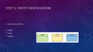


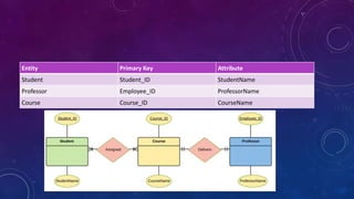
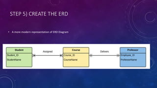


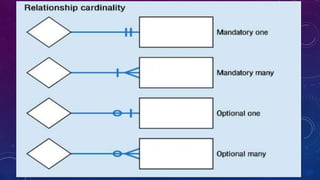


The document discusses entity relationship (ER) models and describes the key concepts including entities, attributes, relationships, keys, ER diagrams, weak entities, and mapping constraints. It provides examples of an ER model for a university database that includes the entities of students, courses, and professors. The model shows the relationships between these entities, their attributes, cardinalities, and a sample ER diagram. Overall, the document provides an overview of ER models and demonstrates how to design an ER schema for a database using a university example.