![Lectures on [V]HDL and HDL
Programming on Xilinx
for
Open Educational Resource
on
Logic Development and Programming (EC221)
by
Dr. Piyush Charan
Assistant Professor
Department of Electronics and Communication Engg.
Integral University, Lucknow](https://image.slidesharecdn.com/unit4hardwarelanguages-201116105814/85/Unit-4-Hardware-Description-Languages-1-320.jpg)
![What is VHDL??
• [V] HDL
[VHSIC] HDL
[Very High Speed Integrated Circuit]
Hardware Description Language
11/2/2020 Dr. Piyush Charan, Dept. of ECE, Integral University, Lucknow 2](https://image.slidesharecdn.com/unit4hardwarelanguages-201116105814/85/Unit-4-Hardware-Description-Languages-2-320.jpg)
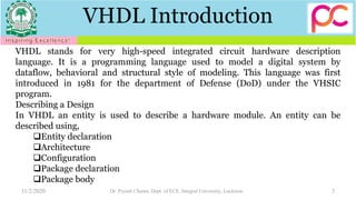
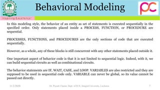
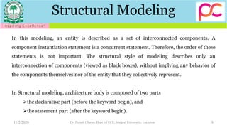
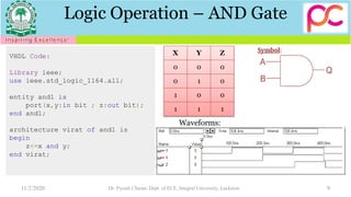
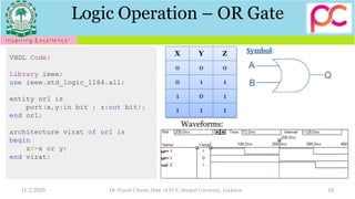
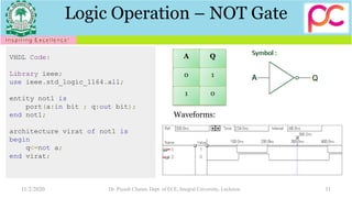
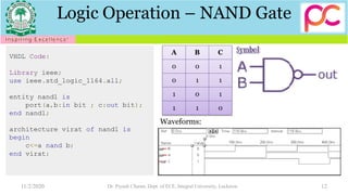
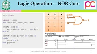
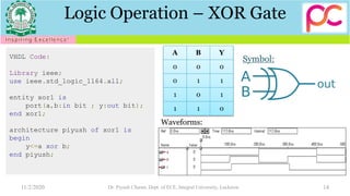
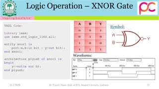

This document contains a summary of a lecture on VHDL and HDL programming on Xilinx. It begins with an introduction to VHDL, explaining that VHDL stands for Very High Speed Integrated Circuit Hardware Description Language. It then discusses different ways of describing hardware designs in VHDL, including entity declarations, architectures, and modeling styles like dataflow, behavioral, and structural. The remainder of the document provides code examples and truth tables for common logic gates like AND, OR, NOT, NAND, NOR, XOR, and XNOR gates.


![Ece iv-fundamentals of hdl [10 ec45]-notes](https://cdn.slidesharecdn.com/ss_thumbnails/ece-iv-fundamentalsofhdl10ec45-notes-150103114952-conversion-gate02-thumbnail.jpg?width=640&height=640&fit=bounds)