Unit 3.
a) RailwayStations and Yards
Introduction
A railway station is that place on a railway line where traffic is booked and dealt
with and where trains are given the authority to proceed forward. Sometimes only one
of these functions is carried out at a station and accordingly it is classified as a flag
station or a block station. In the case of a flag station, there are arrangements for dealing
with traffic but none for controlling the movement of the trains. In the case of a block
station, a train cannot proceed further without obtaining permission from the next
station and traffic may or may not be dealt with. However, most railway stations
perform both the functions indicated above.
Purpose of a Railway Station
A railway station is provided for one or more of the following purposes.
To entrain or detrain passengers
To load or unload goods or parcels
To control the movement of trains
To enable trains to cross each other in the case of a single-line section
To enable faster trains to overtake slower ones
To enable locomotives to refuel, whether it is diesel, water, or coal
To attach or detach coaches or wagons to trains
To collect food and water for passengers
To provide facilities for change of engines and crew/staff
To enable sorting out of wagons and bogies to form new trains
To provide facilities and give shelter to passengers in the case of emergencies
such as floods and accidents, which disrupt traffic.
Selection of Site for a Railway Station
The following factors are considered when selecting a site for a railway station.
Adequate land
There should be adequate land available for the station building, not only for the
proposed line but also for any future expansion. The proposed area should also be
without any religious buildings.
Level area with good drainage
The proposed site should preferably be on a fairly level ground with good
drainage arrangements. It should be possible to provide the maximum permissible
gradient in the yard. In India, the maximum permissible gradient adopted is 1 in 400,
but a gradient of 1 in 1000 is desirable.
Alignment
2.
The station siteshould preferably have a straight alignment so that the various
signals are clearly visible. The proximity of the station site to a curve presents a number
of operational problems.
Easy accessibility
The station site should be easily accessible. The site should be near villages and
towns. Nearby villages should be connected to the station by means of approach roads
for the convenience of passengers.
Water supply arrangement
When selecting the site, it should be verified that adequate water supply is
available for passengers and operational needs.
Facilities Required at Railway Stations
The passenger station is the gateway through which people find their way into a
town or community. A first impression is a lasting one and, hence, a well-designed
station building with well-maintained surroundings is important. Whilst service is the
main consideration, the type and finish of a station building should be, as far as
practicable, in keeping with the best standards of civic amenities available in that area.
A large passenger station should provide for facilities corresponding to the
anticipated demands of at least the first 20 years of its life, with provisions for future
expansion. The facilities required at stations are broadly classified into the following
main groups.
Passenger requirements
This includes waiting rooms and retiring rooms, refreshment rooms and tea stalls,
enquiry and reservation offices, bathrooms and toilets, drinking water supply, platform
and platform sheds, and approach roads.
Traffic requirements
This includes goods sheds and platforms, station buildings, station master‘s
office and other offices, signal and signal cabins, reception and departure lines and
sidings, arrangements for dealing with broken down trains, and station equipment.
Locomotive, carriage, and wagon requirements
This includes the locomotive shed, watering or fuelling facilities, turntable,
inspection pits, ash pits, ashtrays, etc.
Staff requirements
This includes rest houses for officers and staff, running rooms for guards and
drivers, staff canteens, etc.
Requirements of a Passenger Station Yard
The main requirements of a passenger yard are the following.
It should be possible to lower the signals for the reception of trains from different
directions at the same time. This facility is particularly necessary at junction
3.
stations so thatall the trains what are to be connected with each other may be
received at the same time.
Unless all trains are booked to stop at the station, it should be possible to run a
train through the station at a prescribed speed.
In the case of an engine changing station, an engine coming from or going to a
shed should cause minimum interference in the arrival and departure of trains.
An adequate number of platforms should be provided so that all trains can be
dealt with at the same time.
There should be convenient sidings where extra carriages can be stabled after
having been detached from trains or before their attachment to trains.
There should be provision of facilities for dealing with special traffic such as
pilgrim and tourist traffic, parcels in wagon loads, livestock, and motor cars.
Stabling lines, washing lines, sick lines, etc., should be provided as per
requirement.
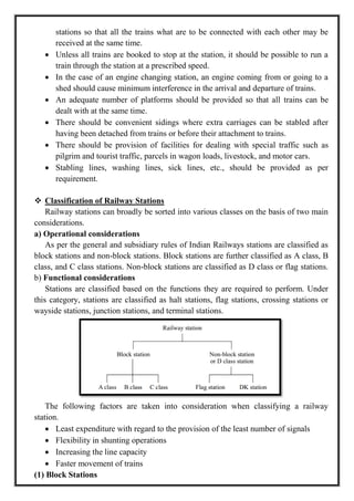
Classification of Railway Stations
Railway stations can broadly be sorted into various classes on the basis of two main
considerations.
a) Operational considerations
As per the general and subsidiary rules of Indian Railways stations are classified as
block stations and non-block stations. Block stations are further classified as A class, B
class, and C class stations. Non-block stations are classified as D class or flag stations.
b) Functional considerations
Stations are classified based on the functions they are required to perform. Under
this category, stations are classified as halt stations, flag stations, crossing stations or
wayside stations, junction stations, and terminal stations.
The following factors are taken into consideration when classifying a railway
station.
Least expenditure with regard to the provision of the least number of signals
Flexibility in shunting operations
Increasing the line capacity
Faster movement of trains
(1) Block Stations
4.
A block stationis a station at which the driver has to obtain an ‗authority to proceed‘
in order to enter the next block section. In a railway system that is inclusive of block
stations, the entire railway line is divided into convenient block sections of 5 to 10 km
and a block station is provided at the end of each block. This system ensures that a
suitable ‗space interval‘ is provided between running trains so that there are no
collisions and accidents.
There are three types of block stations.
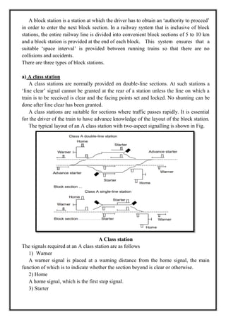
a) A class station
A class stations are normally provided on double-line sections. At such stations a
‗line clear‘ signal cannot be granted at the rear of a station unless the line on which a
train is to be received is clear and the facing points set and locked. No shunting can be
done after line clear has been granted.
A class stations are suitable for sections where traffic passes rapidly. It is essential
for the driver of the train to have advance knowledge of the layout of the block station.
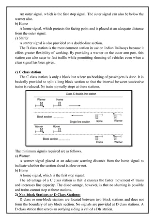
The typical layout of an A class station with two-aspect signalling is shown in Fig.
A Class station
The signals required at an A class station are as follows
1) Warner
A warner signal is placed at a warning distance from the home signal, the main
function of which is to indicate whether the section beyond is clear or otherwise.
2) Home
A home signal, which is the first stop signal.
3) Starter
5.
A starter signalis placed at an adequate distance from the home signal and marks the
point up to which the line should be clear so that the train can be given permission to
approach.
4) Advance starter
This signal is optional and is provided to allow the drivers to further increase the
speed of the trains.
Advantages
(a) More economical vis-à-vis B class stations because of the use of fewer signals.
(b) Ensures the safety of the train because of the provision a warner signal ahead of a
home signal.
(c) Trains normally stop within the station limits.
Disadvantages
(a) No shunting is possible once line clear has been granted.
(b) Another clear disadvantage of A class stations, is that a line at the station has to be
kept clear up to the starter signal once the line clear signal has been given, and as such
the flexibility of working and shunting is restricted.
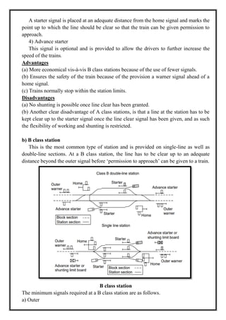
b) B class station
This is the most common type of station and is provided on single-line as well as
double-line sections. At a B class station, the line has to be clear up to an adequate
distance beyond the outer signal before ‗permission to approach‘ can be given to a train.
B class station
The minimum signals required at a B class station are as follows.
a) Outer
6.
An outer signal,which is the first stop signal. The outer signal can also be below the
warner also.
b) Home
A home signal, which protects the facing point and is placed at an adequate distance
from the outer signal.
c) Starter
A starter signal is also provided on a double-line section.
The B class station is the most common station in use on Indian Railways because it
offers greater flexibility of working. By providing a warner on the outer arm post, this
station can also cater to fast traffic while permitting shunting of vehicles even when a
clear signal has been given.
c) C class station
The C class station is only a block hut where no booking of passengers is done. It is
basically provided to split a long block section so that the interval between successive
trains is reduced. No train normally stops at these stations.
The minimum signals required are as follows.
a) Warner
A warner signal placed at an adequate warning distance from the home signal to
indicate whether the section ahead is clear or not.
b) Home
A home signal, which is the first stop signal.
The advantage of a C class station is that it ensures the faster movement of trains
and increases line capacity. The disadvantage, however, is that no shunting is possible
and trains cannot stop at these stations.
2) Non-block Stations or D Class Stations:
D class or non-block stations are located between two block stations and does not
form the boundary of any block section. No signals are provided at D class stations. A
D class station that serves an outlying siding is called a DK station.
7.
At such astation, the siding takes off through a crossover, which can be operated
only with the help of a key, which in turn is released with the help of a ball token. A
―D‖ class station that serves no siding is called a flag station.
3) Functional Classification of Stations
The layout of stations varies in size and importance according to the type and
volume of traffic handled and according to their locations with respect to cities or
industrial areas. Broadly speaking, the layouts required for passenger stations and their
yards can be divided into the following categories for the purpose of study.
(a) Halts
(b) Flag stations
(c) Roadside or crossing stations
(d) Junction stations
(e) Terminal stations
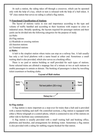
a) Halts:
A halt is the simplest station where trains can stop on a railway line. A halt usually
has only a rail level platform with a name board at either end. Sometimes a small
waiting shed is also provided, which also serves as a booking office.
There is no yard or station building or staff provided for such types of stations.
Some selected trains are allotted a stoppage line of a minute or two at such stations to
enable passengers to entrain or detrain. The booking of passengers is done by travelling
ticket examiners or booking clerks.
Layout of Halt station
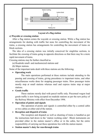
b) Flag station
A flag station is more important as a stop-over for trains than a halt and is provided
with a station building and staff. On controlled sections, a flag station is equipped with
either a Morse telegraph or a control phone, which is connected to one of the stations on
either side to facilitate easy communication.
A flag station is usually provided with a small waiting hall and booking office,
platforms and benches, and arrangements for drinking water. Sometimes a flag station
is also provided with a siding for stabling wagons booked for that station.
8.
Layout of aflag station
c) Wayside or crossing station
After a flag station comes the wayside or crossing station. While a flag station has
arrangements for dealing with traffic but none for controlling the movement of the
trains, a crossing station has arrangements for controlling the movement of trains on
block sections.
The idea of a crossing station was initially conceived for singleline sections, to
facilitate the crossing of trains going in opposite directions so that there may be a more
rapid movement of trains.
Crossing stations may be further classified as
(a) Roadside small- and mediumsized stations and
(b) Major stations.
Some of the important tasks dealt with these stations are the following.
Operating work
The main operations performed at these stations include attending to the
passing and crossing of trains, giving precedence to important trains, and other
miscellaneous works done for stopping passenger trains. Slow passenger trains
mostly stop at small stations whereas mail and express trains stop at major
stations.
Goods traffic
These stations mostly deal with parcel traffic only. Piecemeal wagon load
goods traffic is now being accepted on roadside stations as per the new policy of
the Railway Ministry with effect from December 1994.
Operation of points and signals
The operation of points and signals is controlled either by a central cabin
or two cabins at either end of the station.
Reception and dispatch of trains
The reception and dispatch as well as shunting of trains is handled as per
the instructions laid down in the ‗station working order‘. Block instruments are
provided either in the station master‘s office or in the cabin, but the entire
responsibility of carrying out these operations lies with the station master.
Station master’s duty for run-through trains
9.
When a trainruns through the station, the station master should stand
opposite his office in proper uniform and exchange ‗all right‘ signals with the
driver and guard of the train. He should watch the running train carefully and if
there are any unusual occurrences such as the incidence of a hot box, he should
instruct the station officials in advance to stop and examine the train.
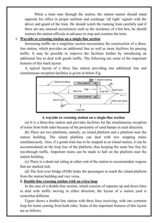
1. Wayside or crossing station on a single-line section
Increasing traffic on a singleline section necessitates the construction of a three-
line station, which provides an additional line as well as more facilities for passing
traffic. It may be possible to improve the facilities further by introducing an
additional line to deal with goods traffic. The following are some of the important
features of this track layout.
A typical layout of a three line station providing one additional line and
simultaneous reception facilities is given in below Fig.
A wayside or crossing station on a single-line section
(a) It is a three-line station and provides facilities for the simultaneous reception
of trains from both sides because of the proximity of sand humps in each direction.
(b) There are two platforms, namely, an island platform and a platform near the
station building. The island platform can deal with two stopping trains
simultaneously. Also, if a goods train has to be stopped at an island station, it can be
accommodated on the loop line of the platform, thus keeping the main line free for
run-through traffic. Important trains can be made to halt on the platform near the
station building.
(c) There is a dead end siding at either end of the station to accommodate wagons
that are marked sick.
(d) The foot over bridge (FOB) helps the passengers to reach the island platform
from the station building and vice versa.
2. Double-line crossing station with an extra loop
In the case of a double-line section, which consists of separate up and down lines
to deal with traffic moving in either direction, the layout of a station yard is
somewhat different.
Figure shows a double-line station with three lines receiving, with one common
loop for trains coming from both sides. Some of the important features of this layout
are as follows.
10.
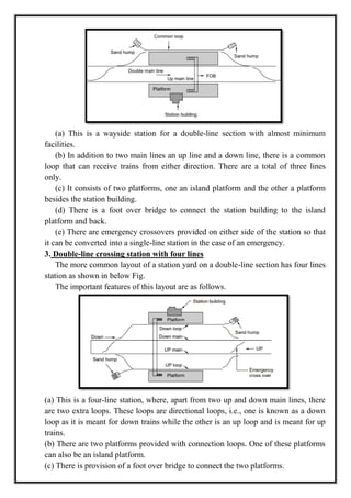
(a) This isa wayside station for a double-line section with almost minimum
facilities.
(b) In addition to two main lines an up line and a down line, there is a common
loop that can receive trains from either direction. There are a total of three lines
only.
(c) It consists of two platforms, one an island platform and the other a platform
besides the station building.
(d) There is a foot over bridge to connect the station building to the island
platform and back.
(e) There are emergency crossovers provided on either side of the station so that
it can be converted into a single-line station in the case of an emergency.
3. Double-line crossing station with four lines
The more common layout of a station yard on a double-line section has four lines
station as shown in below Fig.
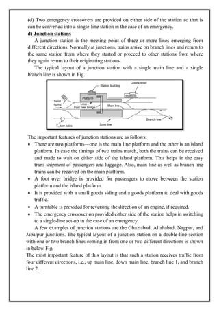
The important features of this layout are as follows.
(a) This is a four-line station, where, apart from two up and down main lines, there
are two extra loops. These loops are directional loops, i.e., one is known as a down
loop as it is meant for down trains while the other is an up loop and is meant for up
trains.
(b) There are two platforms provided with connection loops. One of these platforms
can also be an island platform.
(c) There is provision of a foot over bridge to connect the two platforms.
11.
(d) Two emergencycrossovers are provided on either side of the station so that is
can be converted into a single-line station in the case of an emergency.
d) Junction stations
A junction station is the meeting point of three or more lines emerging from
different directions. Normally at junctions, trains arrive on branch lines and return to
the same station from where they started or proceed to other stations from where
they again return to their originating stations.
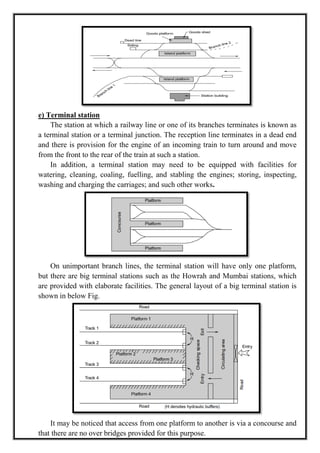
The typical layout of a junction station with a single main line and a single
branch line is shown in Fig.
The important features of junction stations are as follows:
There are two platforms—one is the main line platform and the other is an island
platform. In case the timings of two trains match, both the trains can be received
and made to wait on either side of the island platform. This helps in the easy
trans-shipment of passengers and luggage. Also, main line as well as branch line
trains can be received on the main platform.
A foot over bridge is provided for passengers to move between the station
platform and the island platform.
It is provided with a small goods siding and a goods platform to deal with goods
traffic.
A turntable is provided for reversing the direction of an engine, if required.
The emergency crossover on provided either side of the station helps in switching
to a single-line set-up in the case of an emergency.
A few examples of junction stations are the Ghaziabad, Allahabad, Nagpur, and
Jabalpur junctions. The typical layout of a junction station on a double-line section
with one or two branch lines coming in from one or two different directions is shown
in below Fig.
The most important feature of this layout is that such a station receives traffic from
four different directions, i.e., up main line, down main line, branch line 1, and branch
line 2.
12.
e) Terminal station
Thestation at which a railway line or one of its branches terminates is known as
a terminal station or a terminal junction. The reception line terminates in a dead end
and there is provision for the engine of an incoming train to turn around and move
from the front to the rear of the train at such a station.
In addition, a terminal station may need to be equipped with facilities for
watering, cleaning, coaling, fuelling, and stabling the engines; storing, inspecting,
washing and charging the carriages; and such other works.
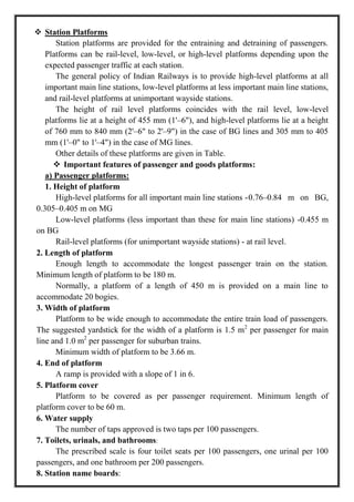
On unimportant branch lines, the terminal station will have only one platform,
but there are big terminal stations such as the Howrah and Mumbai stations, which
are provided with elaborate facilities. The general layout of a big terminal station is
shown in below Fig.
It may be noticed that access from one platform to another is via a concourse and
that there are no over bridges provided for this purpose.
13.
Station Platforms
Stationplatforms are provided for the entraining and detraining of passengers.
Platforms can be rail-level, low-level, or high-level platforms depending upon the
expected passenger traffic at each station.
The general policy of Indian Railways is to provide high-level platforms at all
important main line stations, low-level platforms at less important main line stations,
and rail-level platforms at unimportant wayside stations.
The height of rail level platforms coincides with the rail level, low-level
platforms lie at a height of 455 mm (1'–6"), and high-level platforms lie at a height
of 760 mm to 840 mm (2'–6" to 2'–9") in the case of BG lines and 305 mm to 405
mm (1'–0" to 1'–4") in the case of MG lines.
Other details of these platforms are given in Table.
Important features of passenger and goods platforms:
a) Passenger platforms:
1. Height of platform
High-level platforms for all important main line stations -0.76–0.84 m on BG,
0.305–0.405 m on MG
Low-level platforms (less important than these for main line stations) -0.455 m
on BG
Rail-level platforms (for unimportant wayside stations) - at rail level.
2. Length of platform
Enough length to accommodate the longest passenger train on the station.
Minimum length of platform to be 180 m.
Normally, a platform of a length of 450 m is provided on a main line to
accommodate 20 bogies.
3. Width of platform
Platform to be wide enough to accommodate the entire train load of passengers.
The suggested yardstick for the width of a platform is 1.5 m2
per passenger for main
line and 1.0 m2
per passenger for suburban trains.
Minimum width of platform to be 3.66 m.
4. End of platform
A ramp is provided with a slope of 1 in 6.
5. Platform cover
Platform to be covered as per passenger requirement. Minimum length of
platform cover to be 60 m.
6. Water supply
The number of taps approved is two taps per 100 passengers.
7. Toilets, urinals, and bathrooms:
The prescribed scale is four toilet seats per 100 passengers, one urinal per 100
passengers, and one bathroom per 200 passengers.
8. Station name boards:
14.
Two station nameboards to be placed, one on each side of the platform,
perpendicular to the track.
Name of the station to be written in Hindi, English, and the regional language.
Height of underside of boards to be 1.8 m.
b) Goods platforms
1. Height of platform
BG 1.07 m, MG 0.69 m, and NG 0.61 m
2. Length of platform
Adequate enough to deal with goods received or dispatched; normally not less
than 60 m.
3. Width of platform
Depends upon volume of traffic, minimum width specified is 3.1 m.
4. Other facilities
Weighing facilities, direct access road, paved platform, etc.
Types of Yards
A yard is a system of tracks laid out to deal with the passenger as well as goods
traffic being handled by the railways. This includes receipt and dispatch of trains apart
from stabling, sorting, marshalling, and other such functions.
Yards are normally classified into the following categories.
(a)Coaching yard
The main function of a coaching yard is to deal with the reception and dispatch of
passenger trains. Depending upon the volume of traffic, this yard provides facilities
such as watering and fuelling of engines, washing of rakes, examination of coaches,
charging of batteries, and trans-shipment of passengers.
(b)Goods yard
A goods yard provides facilities for the reception, stabling, loading, unloading,
and dispatch of goods wagons. Most goods yards deal with a full train load of
wagons. No sorting, marshalling, and reforming is done at goods yards except in the
case of ‗sick‘ wagons or a few wagons booked for that particular station. Separate
goods sidings are provided with the platforms for the loading and unloading of the
goods being handled at that station.
(c) Marshalling yard
A goods yard which deals with the sorting of goods wagons to form new goods
trains is called a marshalling yard. The marshalling yard is a yard where goods trains
are received and sorted out, and new trains are formed and finally dispatched to
various destinations.
This yard receives loaded as well as empty goods wagons from different stations
for further booking to different destinations. These wagons are separated, sorted out,
15.
properly marshalled, andfinally dispatched bearing full trainloads to various
destinations. The marshalling of trains is so done that the wagons can be
conveniently detached without much shunting en route at wayside stations.
(d)Locomotive yard
This is the yard which houses the locomotive. Facilities for watering, fuelling,
examining locomotives, repairing, etc., are provided in this yard. The yard layout is
designed depending upon the number of locomotives required to be housed in the
locomotive shed. The facilities are so arranged that a requisite number of
locomotives are serviced simultaneously and are readily available for hauling the
trains. Such yards should have adequate space for storing fuel. The water supply
should be adequate for washing the locomotives and servicing them.
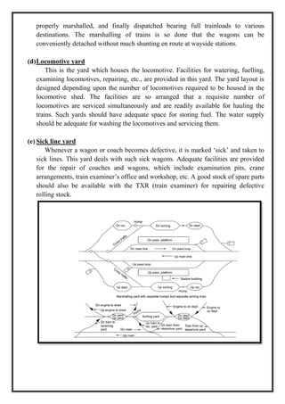
(e) Sick line yard
Whenever a wagon or coach becomes defective, it is marked ‗sick‘ and taken to
sick lines. This yard deals with such sick wagons. Adequate facilities are provided
for the repair of coaches and wagons, which include examination pits, crane
arrangements, train examiner‘s office and workshop, etc. A good stock of spare parts
should also be available with the TXR (train examiner) for repairing defective
rolling stock.
16.
B) Signalling andInterlocking
Introduction
The purpose of signalling and interlocking is primarily to control and regulate the
movement of trains safely and efficiently. Signalling includes the use and working
of signals, points, block instruments, and other allied equipment in a predetermined
manner for the safe and efficient running of trains.
Signalling enables the movement of trains to be controlled in such a way that the
existing tracks are utilized to the maximum. In fact in railway terminology signalling
is a medium of communication between the station master or the controller sitting in
a remote place in the office and the driver of the train.
The history of signalling goes back to the olden days when two policemen on
horseback were sent ahead of the train to ensure that the tracks were clear and to
regulate the movement of the trains.
In later years, policemen in uniform were placed at regular intervals to regulate
the movement of trains. Railway signalling in its present form was introduced for
the first time in England in 1842, whereas interlocking was developed subsequently
in 1867.
Objectives of Signalling :
The objectives of signalling are as follows.
(a) To regulate the movement of trains so that they run safely at maximum
permissible speeds.
(b) To maintain a safe distance between trains that was running on the same line in
the same direction.
(c) To ensure the safety of two or more trains those have to cross or approach each
other.
(d) To provide facilities for safe and efficient shunting.
(e) To regulate the arrival and departure of trains from the station yard.
(f) To guide the trains to run at restricted speeds during the maintenance and repair
of tracks.
(g) To ensure the safety of the train when it comes in contact with road traffic at
level crossings.
Classification of Signals
Based on different characteristics
17.
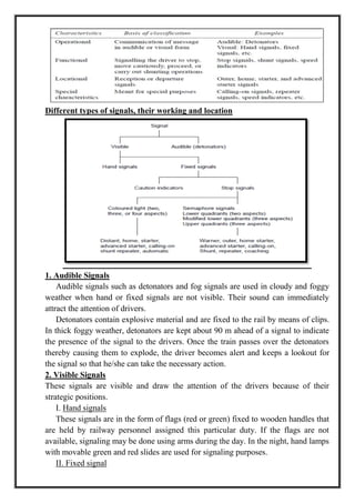
Different types ofsignals, their working and location
1. Audible Signals
Audible signals such as detonators and fog signals are used in cloudy and foggy
weather when hand or fixed signals are not visible. Their sound can immediately
attract the attention of drivers.
Detonators contain explosive material and are fixed to the rail by means of clips.
In thick foggy weather, detonators are kept about 90 m ahead of a signal to indicate
the presence of the signal to the drivers. Once the train passes over the detonators
thereby causing them to explode, the driver becomes alert and keeps a lookout for
the signal so that he/she can take the necessary action.
2. Visible Signals
These signals are visible and draw the attention of the drivers because of their
strategic positions.
I. Hand signals
These signals are in the form of flags (red or green) fixed to wooden handles that
are held by railway personnel assigned this particular duty. If the flags are not
available, signaling may be done using arms during the day. In the night, hand lamps
with movable green and red slides are used for signaling purposes.
II. Fixed signal
18.
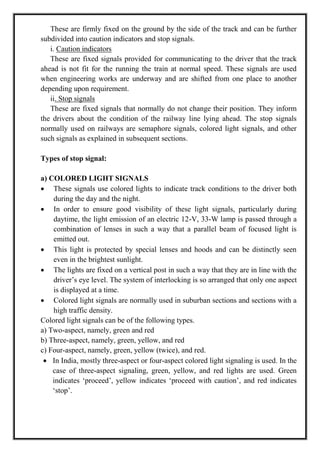
These are firmlyfixed on the ground by the side of the track and can be further
subdivided into caution indicators and stop signals.
i. Caution indicators
These are fixed signals provided for communicating to the driver that the track
ahead is not fit for the running the train at normal speed. These signals are used
when engineering works are underway and are shifted from one place to another
depending upon requirement.
ii. Stop signals
These are fixed signals that normally do not change their position. They inform
the drivers about the condition of the railway line lying ahead. The stop signals
normally used on railways are semaphore signals, colored light signals, and other
such signals as explained in subsequent sections.
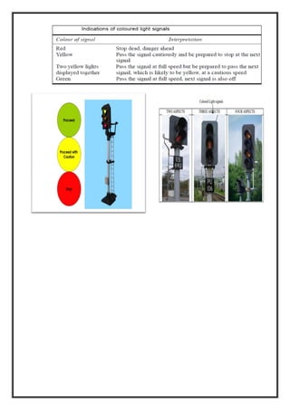
Types of stop signal:
a) COLORED LIGHT SIGNALS
These signals use colored lights to indicate track conditions to the driver both
during the day and the night.
In order to ensure good visibility of these light signals, particularly during
daytime, the light emission of an electric 12-V, 33-W lamp is passed through a
combination of lenses in such a way that a parallel beam of focused light is
emitted out.
This light is protected by special lenses and hoods and can be distinctly seen
even in the brightest sunlight.
The lights are fixed on a vertical post in such a way that they are in line with the
driver‘s eye level. The system of interlocking is so arranged that only one aspect
is displayed at a time.
Colored light signals are normally used in suburban sections and sections with a
high traffic density.
Colored light signals can be of the following types.
a) Two-aspect, namely, green and red
b) Three-aspect, namely, green, yellow, and red
c) Four-aspect, namely, green, yellow (twice), and red.
In India, mostly three-aspect or four-aspect colored light signaling is used. In the
case of three-aspect signaling, green, yellow, and red lights are used. Green
indicates ‗proceed‘, yellow indicates ‗proceed with caution‘, and red indicates
‗stop‘.
20.
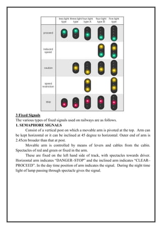
3 Fixed Signals
Thevarious types of fixed signals used on railways are as follows.
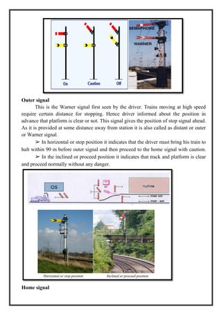
1. SEMAPHORE SIGNALS
Consist of a vertical post on which a movable arm is pivoted at the top. Arm can
be kept horizontal or it can be inclined at 45 degree to horizontal. Outer end of arm is
2.45cm broader than that at post.
Movable arm is controlled by means of levers and cables from the cabin.
Spectacles of red and green or fixed in the arm.
These are fixed on the left hand side of track, with spectacles towards driver.
Horizontal arm indicates ―DANGER–STOP‖ and the inclined arm indicates ―CLEAR–
PROCEED‖. In the day time position of arm indicates the signal. During the night time
light of lamp passing through spectacle gives the signal.
21.
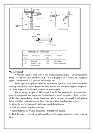
Warner signal
A Warnersignal is used only in two-aspect signaling (2LQ – Lower Quadrant,
MLQ - Modified Lower Quadrant, 2CL – Color Light). This is similar to semaphore
signal. The difference is it contains a fish tailed arm.
These signals are placed ahead the semaphore signals to warn the driver before
entering the railway station. Sometimes both Warner and semaphore signals are placed
on the same pole at 2m distance between each on the pole.
Warner signals are placed 540m away from the first stop signal. Its purpose is to
warn of an approach to a stop signal further ahead, or to advise a driver of the condition
of the block section being entered. Sometimes Warner signals are provided with yellow
lights instead of red to distinguish them from semaphore signals during nights.
➢ When the arm is horizontal – indicates signal ahead is stop
➢ Both horizontal – stop line not clear
➢ Semaphore lower, Warner horizontal – proceed with caution
➢ Both lowered – proceed on with confidence (this section and next section both are
clear)
22.
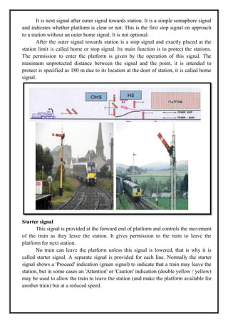
Outer signal
This isthe Warner signal first seen by the driver. Trains moving at high speed
require certain distance for stopping. Hence driver informed about the position in
advance that platform is clear or not. This signal gives the position of stop signal ahead.
As it is provided at some distance away from station it is also called as distant or outer
or Warner signal.
➢ In horizontal or stop position it indicates that the driver must bring his train to
halt within 90 m before outer signal and then proceed to the home signal with caution.
➢ In the inclined or proceed position it indicates that track and platform is clear
and proceed normally without any danger.
Home signal
23.
It is nextsignal after outer signal towards station. It is a simple semaphore signal
and indicates whether platform is clear or not. This is the first stop signal on approach
to a station without an outer home signal. It is not optional.
After the outer signal towards station is a stop signal and exactly placed at the
station limit is called home or stop signal. Its main function is to protect the stations.
The permission to enter the platform is given by the operation of this signal. The
maximum unprotected distance between the signal and the point, it is intended to
protect is specified as 180 m due to its location at the door of station, it is called home
signal.
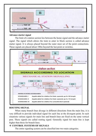
Starter signal
This signal is provided at the forward end of platform and controls the movement
of the train as they leave the station. It gives permission to the train to leave the
platform for next station.
No train can leave the platform unless this signal is lowered, that is why it is
called starter signal. A separate signal is provided for each line. Normally the starter
signal shows a 'Proceed' indication (green signal) to indicate that a train may leave the
station, but in some cases an 'Attention' or 'Caution' indication (double yellow / yellow)
may be used to allow the train to leave the station (and make the platform available for
another train) but at a reduced speed.
24.
Advance starter signal
Thelimit of a station section lies between the home signal and the advance starter
signal. The signal which allows the train to enter in block section is called advance
starter signal. It is always placed beyond the outer most set of the point connections.
These signals are placed about 180m beyond the last point or switches.
ROUTING SIGNAL
When many branch lines diverge in different directions from the main line, it is
very difficult to provide individual signal for each line at the divergent point. In such
situations various signals for main line and branch lines are fixed on the same vertical
post. These signals are called routing signal. Generally signal for main line is kept
higher than those for branch lines.
CONTROL SYSTEMS OF SIGNALS
The entire signaling system can be classified into two main categories.
25.
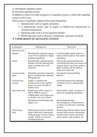
A. Mechanical signalingsystem
B. Electrical signaling system
In addition to these two main categories of signaling systems, a solid-state signaling
system is also in use.
Each system of signaling comprises four main components.
1. Operated units such as signals and points
2. A transmission system such as single- or double-wire transmission or
electrical transmission
3. Operating units such as levers and press buttons
4. Monitoring units such as detectors, treadle bars, and track circuiting
COMPARISON OF SIGNALING SYSTEM
26.
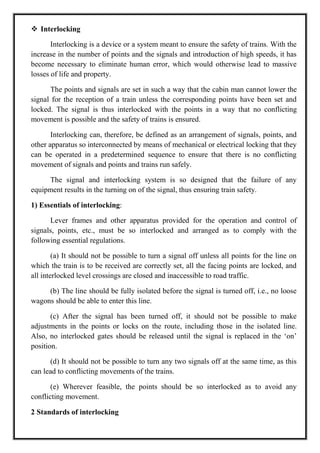
Interlocking
Interlocking isa device or a system meant to ensure the safety of trains. With the
increase in the number of points and the signals and introduction of high speeds, it has
become necessary to eliminate human error, which would otherwise lead to massive
losses of life and property.
The points and signals are set in such a way that the cabin man cannot lower the
signal for the reception of a train unless the corresponding points have been set and
locked. The signal is thus interlocked with the points in a way that no conflicting
movement is possible and the safety of trains is ensured.
Interlocking can, therefore, be defined as an arrangement of signals, points, and
other apparatus so interconnected by means of mechanical or electrical locking that they
can be operated in a predetermined sequence to ensure that there is no conflicting
movement of signals and points and trains run safely.
The signal and interlocking system is so designed that the failure of any
equipment results in the turning on of the signal, thus ensuring train safety.
1) Essentials of interlocking:
Lever frames and other apparatus provided for the operation and control of
signals, points, etc., must be so interlocked and arranged as to comply with the
following essential regulations.
(a) It should not be possible to turn a signal off unless all points for the line on
which the train is to be received are correctly set, all the facing points are locked, and
all interlocked level crossings are closed and inaccessible to road traffic.
(b) The line should be fully isolated before the signal is turned off, i.e., no loose
wagons should be able to enter this line.
(c) After the signal has been turned off, it should not be possible to make
adjustments in the points or locks on the route, including those in the isolated line.
Also, no interlocked gates should be released until the signal is replaced in the ‗on‘
position.
(d) It should not be possible to turn any two signals off at the same time, as this
can lead to conflicting movements of the trains.
(e) Wherever feasible, the points should be so interlocked as to avoid any
conflicting movement.
2 Standards of interlocking
27.
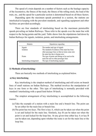
The speed ofa train depends on a number of factors such as the haulage capacity
of the locomotive, the fitness of the track, the fitness of the rolling stock, the load of the
train, etc., and the speed for a particular section is determined based on all these factors.
Depending upon the maximum speeds permitted in a section, the stations are
interlocked in keeping with the prevalent standards, and signalling equipment and other
facilities are provided accordingly.
There are four standards of interlocking based on the maximum permissible
speeds prevailing on Indian Railways. These refer to the speeds over the main line with
respect to the facing points and the yard. Table shows lists the stipulations laid down by
Indian Railways for signals, isolation, points, and interlocking arrangements.
3) Methods of interlocking:
There are basically two methods of interlocking as explained below.
a) Key interlocking
Key interlocking is the simplest method of interlocking and still exists on branch
lines of small stations on Indian Railways. The method involves the manipulation of
keys in one form or the other. This type of interlocking is normally provided with
standard I interlocking with a speed limit below 50 km/h.
The simplest arrangement of key interlocking is accomplished in the following
manner.
(a) Take the example of a station with a main line and a branch line. The point can
be set either for the main line or branch line.
(b)The point has two keys. The first is key A, which can be taken out when the point
is set and locked for the main line. Similarly, key B can be taken out when the
point is set and locked for the loop line. At any given time either key A or key B
can be taken out, depending upon whether the route is set for the main line or the
loop line.
28.
(c) The leverframe operating the signals is provided with two levers. The lever
concerning the main line signal can be operated only by key A and similarly the
branch line signal lever can be operated only by key B.
(d)If the train is to be received on the main line, the points are set and locked for the
main line and key A is released. This key is used for unlocking the main line
signal lever, thus lowering the signal for the main line. Since key A cannot be
used for interlocking and lowering the branch line signal, only the appropriate
signal can be turned off. This type of interlocking is called indirect locking.
In case more than one point is to be operated, the key released at the first point is
used to unlock and operate the second point and so on. The key released at the last point
can then be used for unlocking the lever operating the appropriate signal.
This type of interlocking is also known as succession locking and is also used for
checking conflicting movements in shunting operations. There are other methods of
interlocking with the help of keys, but all of them involve considerably lengthy trips
from the point to the signal levers and from point to point, thereby leading to delays.
Such arrangements are, therefore, satisfactory only for stations that handle very light
traffic.
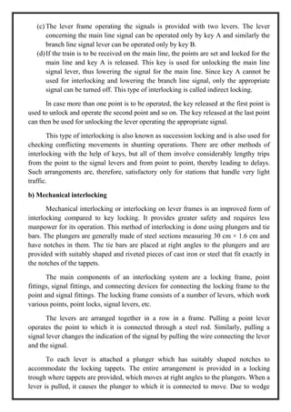
b) Mechanical interlocking
Mechanical interlocking or interlocking on lever frames is an improved form of
interlocking compared to key locking. It provides greater safety and requires less
manpower for its operation. This method of interlocking is done using plungers and tie
bars. The plungers are generally made of steel sections measuring 30 cm × 1.6 cm and
have notches in them. The tie bars are placed at right angles to the plungers and are
provided with suitably shaped and riveted pieces of cast iron or steel that fit exactly in
the notches of the tappets.
The main components of an interlocking system are a locking frame, point
fittings, signal fittings, and connecting devices for connecting the locking frame to the
point and signal fittings. The locking frame consists of a number of levers, which work
various points, point locks, signal levers, etc.
The levers are arranged together in a row in a frame. Pulling a point lever
operates the point to which it is connected through a steel rod. Similarly, pulling a
signal lever changes the indication of the signal by pulling the wire connecting the lever
and the signal.
To each lever is attached a plunger which has suitably shaped notches to
accommodate the locking tappets. The entire arrangement is provided in a locking
trough where tappets are provided, which moves at right angles to the plungers. When a
lever is pulled, it causes the plunger to which it is connected to move. Due to wedge
29.
action, the tappetaccommodated in the notch of the plunger is pushed out at right
angles to the movement of the plunger.
The motion is transmitted to all other tappets that are connected to this tappet
through a tie bar. As a result of this motion, the other tappets either get pushed into or
out of the respective notches of the other plunger depending upon the type of
interlocking provided.
In case the other tappet is free but slips inside the notch of the other plunger, it
locks the lever connected to this plunger. In consequence, the other lever gets locked in
that position and cannot be operated. However, if the tappet was earlier positioned in
the notch of the plunger, thereby locking the lever, and is now out of the notch, the
other lever becomes free to be operated.
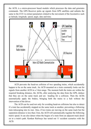
ANTI-COLLISION DEVICE (ACD):
The ACD Network is a Train Collision prevention system designed, developed
and patented by Konkan Railway Corporation Limited (A Public Sector Undertaking of
Ministry of Railways, Government of India).
Its concept was first proposed by the former chairman of Konkan railways Mr. B
raja ram in the 90s.Its patent was filed in the sept 1999 and the patent was granted in the
year 2005. It is a self-acting microprocessor-based data communication device which
when installed on locomotives (along with an auto-braking unit - ABU), guard vans,
stations and level-crossing gates (both manned and unmanned), prevents high-speed
collisions in mid-sections, station areas and at level-crossing gates.
The ACD uses both radio frequency and Global Positioning System (GPS)
through satellites, whereby a train is automatically brought to a halt if the track ahead is
not clear. The train starts braking 3 kms ahead of a blockade.
The Anti-Collision Device (ACD), also called `Raksha Kavach,' imagines setting
up a network of "self-acting" micro-processor based communication devices which
automatically apply brakes on trains that are unknowingly getting into a "collision-like
situation," including before stations and at mid-sections. "At the mid-sections, where
neither the protection of signals nor guidance is available to the driver, the ACD makes
the loco intelligent and extends its capability to detect any collision-like situations in a
range of 3 km, which the driver cannot detect on his own. Situations like collision
between two approaching trains or between a derailed train on one track and an
approaching train on the adjacent tract can thus be prevented, according to the KRCL
official.
The "silent" network of ACD systems can be installed on the locomotives, guard
vans and at stations, which could ensure that trains do not collide at while travelling at
high speeds. Further, if the ACD systems are provided at the level crossing gates (both
manned as well as un-manned), the project could provide protection to the lives of road
users also. "We have tested the commercial prototypes of ACD system, which has been
developed indigenously for the first time in the world. It has been technically proven
30.
during joint fieldtrials with Research Design and Standards Organization, nominated
by the Railways," the official said.
The ACDs are capable of multi functions. For example, while approaching a
station, the Loco ACD gives the "station approach" warning to the driver about 2 km in
rear of the first STOP signal of the station and in case the driver ignores the warning it
will automatically regulate the train speed.
The pilot project implementation of ACD was successfully commissioned on the
North-East Frontier Railway this year. Survey for expanding the system to another
10,000 km falling on the critical and busy sections of the network is almost complete. 2
The installation of this device will go a long way in preventing collision
accidents. The application of this device has been refined to not only prevent mid-
section collisions but also to pre-empt their occurrence in station yards.
The newly engineered solution is integrated with the signaling systems and
interlocking to react appropriately in case collision-like conditions are perceived at the
time of reception and dispatch of trains from a station. The design of crash-worthy
coaches and tight lock couplers with anti climbing features has been finalized and all
future coaches are being made as per the new design.
TECHNOLOGY USED
The heart of the ACD is an Intel 80386 processor that uses the DM&P M617
Intel chipset. It [ACD] has an integrated digital radio modem and works on the
VxWorks Real Time Operating System (RTOS).
Raja ram adds, ―VxWorks, as a platform, is most suitable for real-time
applications. The main modules of the ACD includes a GPS (Global Positioning
System), which picks up signals from the constellation of GPS satellites that are being
exclusively used for this purpose.
The GPS submits the data to the Command and Control Unit (CCU) to extract
the parameters related to the movement of locomotive like latitude, longitude, speed,
angle, date and time.
The antenna of the GPS receiver is fitted outside on the roof of the locomotive.
The user-friendly device helps the driver to know the various positions in the form of
audiovisual indications, like Station Approach, SOS (for head-on, rear-end and side
collision situations) and Gate Open. Another module is the radio trans-receiver, which
transmits the information and commands generated by the CCU and receives the
information being sent by other ACDs when the two systems are within the radio-range
of 3 km.
The final module in the system is the braking mechanism, which envisages the
CCU to take a decision for applying either the normal brake or the emergency brake on
the locomotive as the situation required.
ACD is an intelligent friend to the engine driver, which can act on its own
without any human intervention. It comprises a Command and Control Unit (CCU), a
GPS Receiver, Radio Transmitter and Crew Interface. The CCU, which is the heart of
31.
the ACD, isa micro-processor based module which processes the data and generates
commands. The GPS Receiver picks up signals from GPS satellites and submits the
same to the CCU to extract parameters related to the movement of the locomotive such
as latitude, longitude, speed, angle, date and time.
ACD prevents the head-on collision of two speeding trains, which accidentally
happen to be on the same track. An ACD mounted on a train constantly looks out for
signals from another ACD in a 3-km range. The moment both the trains are within the
required breaking distance, the ACDs, after analyzing the data from the GPS, deduce
that they are on the same track and are heading for a collision. Then the ACDs
automatically apply the brakes, bringing both the trains to a halt without the
intervention of the driver.
The ACD can be used not only for avoiding head-on collisions but also to detect
if a train has accidentally stopped on the same track as another, preventing a following
train telescoping into its rear. Also, if two trains are moving on the same track but the
separation distance is less than 2 km, the ACD will automatically regulate the following
train's speed. It can also detect when the bogies of a train from an adjacent track derail
on to a train's path. Konkan Railways has tested out 11 accident scenarios with the
ACD.
32.
The ACD canbe mounted not only on trains but also be installed at railway
stations, level crossing gates (both manned and unmanned), and on guard vans. If a
station is equipped with an ACD, the driver will receive the ``station approach'' warning
as the train approaches the station. Also, the ACD can sense whether a level crossing
gate is open or damaged and warn the driver, besides regulating the train's speed.
FUNCTIONS OF ACD:-
Continues communication: -
All ACDs within a radius of three kilometers continuously communicate among
themselves giving their ID, status, location, speed, etc. v Detection and Prevention
of Head-on, Rear-end and Side Collisions: –It is the only system in the world to
provide these UNIQUE features even when a train is not protected by a signal, as in
a block section.
Detection of fouling and prevention of collision due to fouling:-
When a Train on main line overshoots the ‗Fouling Mark‘, this system activates and
prevents collision due to fouling.
Detection & generation of Train parting / Jumbling: -
Consequently bringing any approaching train on the adjoining line to a dead stop.
Station Approach Warning to Drivers: -
Can result in saving of Manpower for deployment of detonators during foggy
weather, provided 100% coverage of ACD fitted trains is available on the concerned
ACD route.
Speed limit imposition:-
It limits the train speed to 30 kmph near stations and unmanned level crossing if the
gate is detected as open. Mostly the speed limit is based on ‗preset‘ conditions in
FRS of ACD.
‘Train Approach’ Warning for road users :-
It provides warning at both manned and unmanned level crossings. In addition , at
manned non-interlocked level crossings, reducing the train speed to 30 Kmph in case
the gate is detected in ‗open‘ condition through Gate ACD.
Manual SOS functionality available for Drivers, Guards and Station Masters: -
To bring all trains to a halt within a radial distance of 3 Kms, in emergencies.
Auto Brake Test:-
Generating braking characteristics for a Train ‗without manual feeding‘ of data of
coaches / load - A UNIQUE feature as train characteristics are required to be fed
‗manually‘ in all other systems in the world.
FEATURES OF ACD
(a) Very economical and cost effective.
(b)Easily adaptable and expandable.
(c) Acts automatically to prevent collisions if an eventuality arises.
(d)Does not degrade the existing safety level.
33.
(e) Employs state-of-arthardware and software technology.
(f) No way had side equipment required, hence no requirement of Power.
(g)No cabling on the track required (which is more expensive and
cumbersome).
(h)Less susceptible to Vandalism.
(i) It does not require any inputs to be fed by the crew at the start of journey,
thus human error is eliminated.
APPLICATIONS:-
(a) ACDs can be implemented in railways to prevent collisions and to increase
the tolerance between two consecutive trains running one after another.
(b)Development of high speed trains with high safety measures.
(c) It can be used in heavy vehicles like cranes, earthmovers etc to prevent
accidents and for their safe working in public places.
(d)With few developments can also be used in automobiles for prevention of
road accidents.
(e) ACDs can be used as a tracking device.


![during joint field trials with Research Design and Standards Organization, nominated
by the Railways," the official said.
The ACDs are capable of multi functions. For example, while approaching a
station, the Loco ACD gives the "station approach" warning to the driver about 2 km in
rear of the first STOP signal of the station and in case the driver ignores the warning it
will automatically regulate the train speed.
The pilot project implementation of ACD was successfully commissioned on the
North-East Frontier Railway this year. Survey for expanding the system to another
10,000 km falling on the critical and busy sections of the network is almost complete. 2
The installation of this device will go a long way in preventing collision
accidents. The application of this device has been refined to not only prevent mid-
section collisions but also to pre-empt their occurrence in station yards.
The newly engineered solution is integrated with the signaling systems and
interlocking to react appropriately in case collision-like conditions are perceived at the
time of reception and dispatch of trains from a station. The design of crash-worthy
coaches and tight lock couplers with anti climbing features has been finalized and all
future coaches are being made as per the new design.
TECHNOLOGY USED
The heart of the ACD is an Intel 80386 processor that uses the DM&P M617
Intel chipset. It [ACD] has an integrated digital radio modem and works on the
VxWorks Real Time Operating System (RTOS).
Raja ram adds, ―VxWorks, as a platform, is most suitable for real-time
applications. The main modules of the ACD includes a GPS (Global Positioning
System), which picks up signals from the constellation of GPS satellites that are being
exclusively used for this purpose.
The GPS submits the data to the Command and Control Unit (CCU) to extract
the parameters related to the movement of locomotive like latitude, longitude, speed,
angle, date and time.
The antenna of the GPS receiver is fitted outside on the roof of the locomotive.
The user-friendly device helps the driver to know the various positions in the form of
audiovisual indications, like Station Approach, SOS (for head-on, rear-end and side
collision situations) and Gate Open. Another module is the radio trans-receiver, which
transmits the information and commands generated by the CCU and receives the
information being sent by other ACDs when the two systems are within the radio-range
of 3 km.
The final module in the system is the braking mechanism, which envisages the
CCU to take a decision for applying either the normal brake or the emergency brake on
the locomotive as the situation required.
ACD is an intelligent friend to the engine driver, which can act on its own
without any human intervention. It comprises a Command and Control Unit (CCU), a
GPS Receiver, Radio Transmitter and Crew Interface. The CCU, which is the heart of](https://image.slidesharecdn.com/unit3railwaystationsandyards-250801101429-2794fe55/85/Unit-3-Railway-Stations-and-Yards-pdf-30-320.jpg)