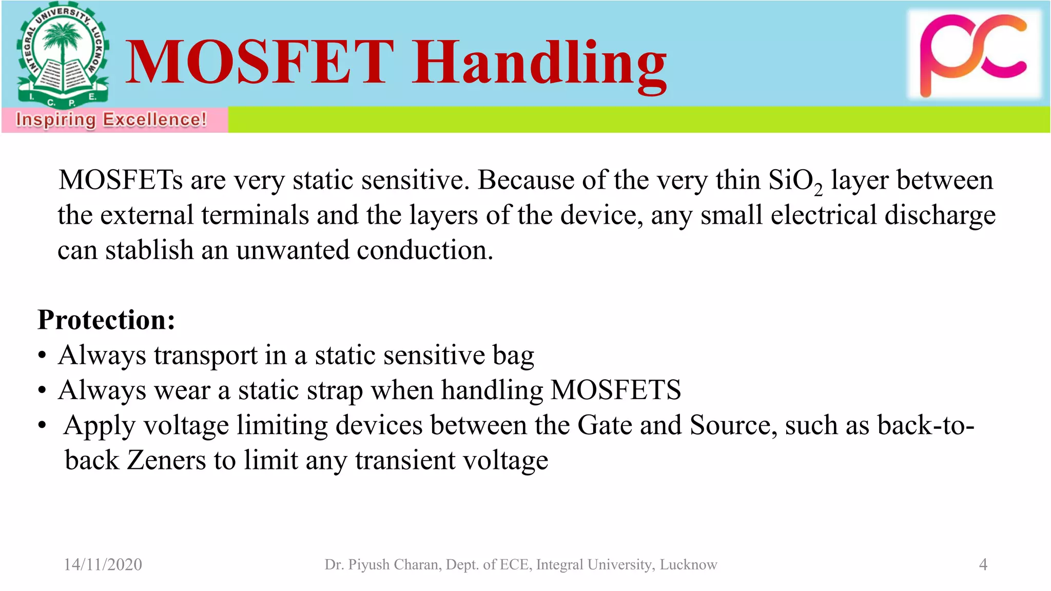
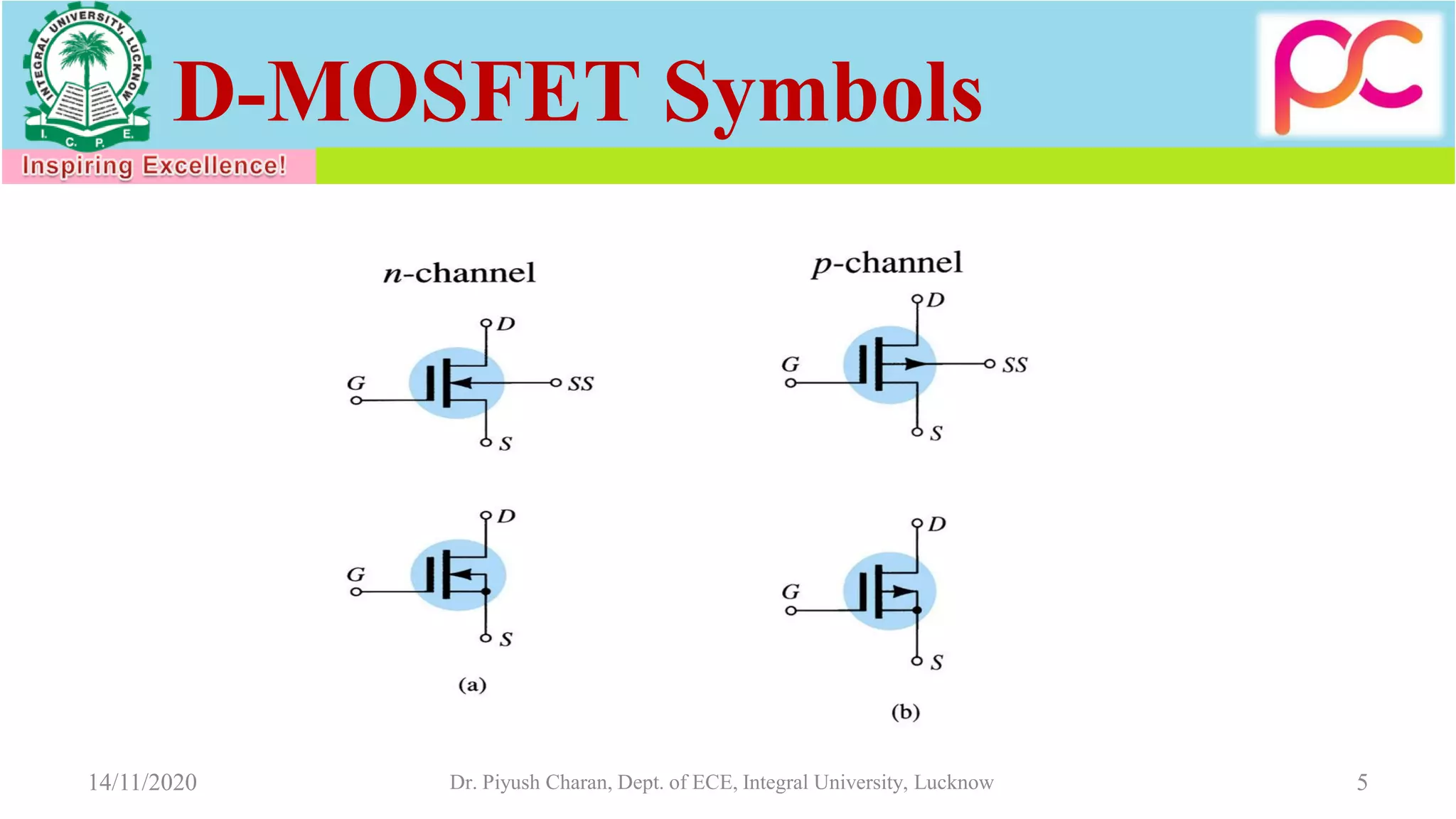
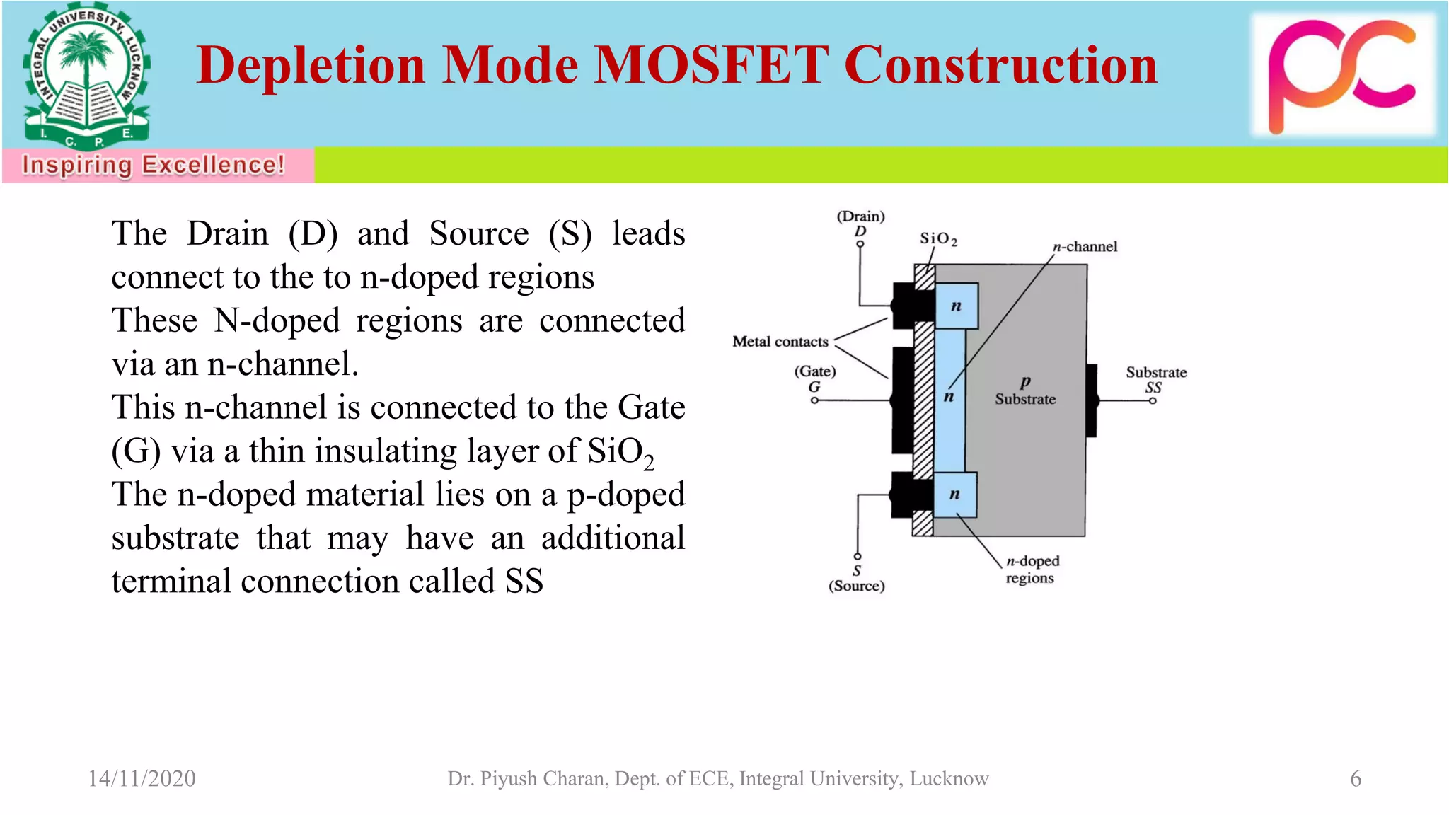
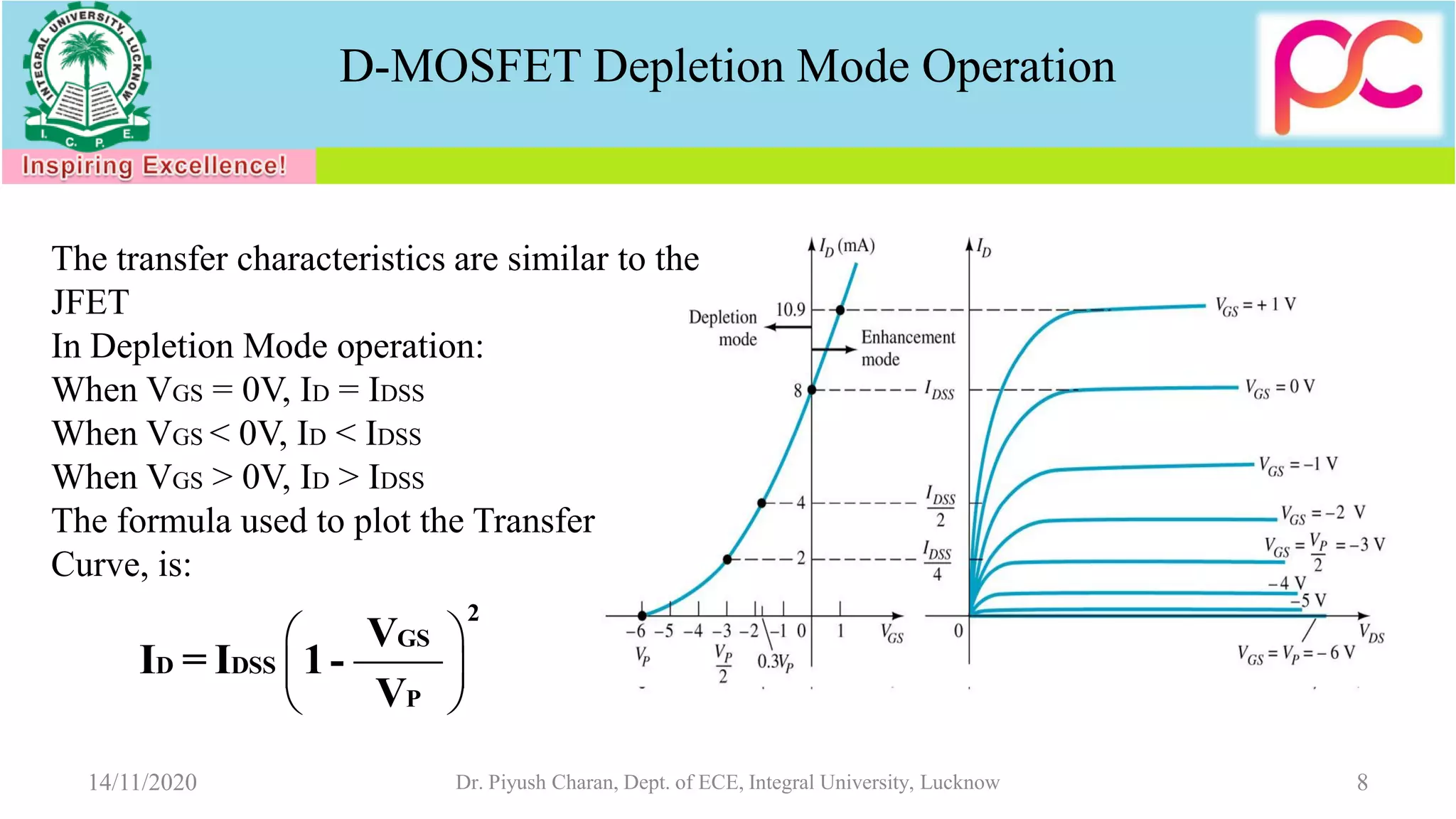
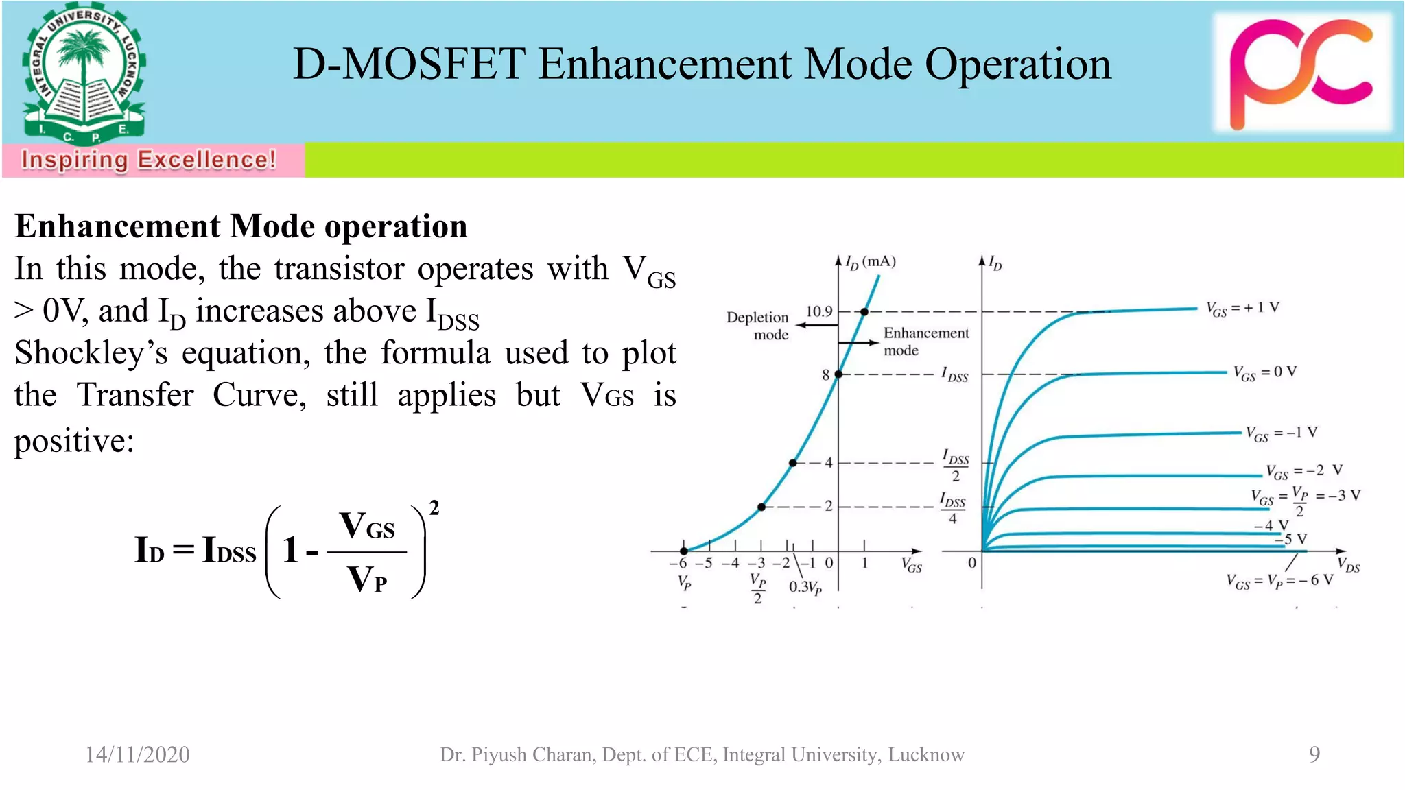
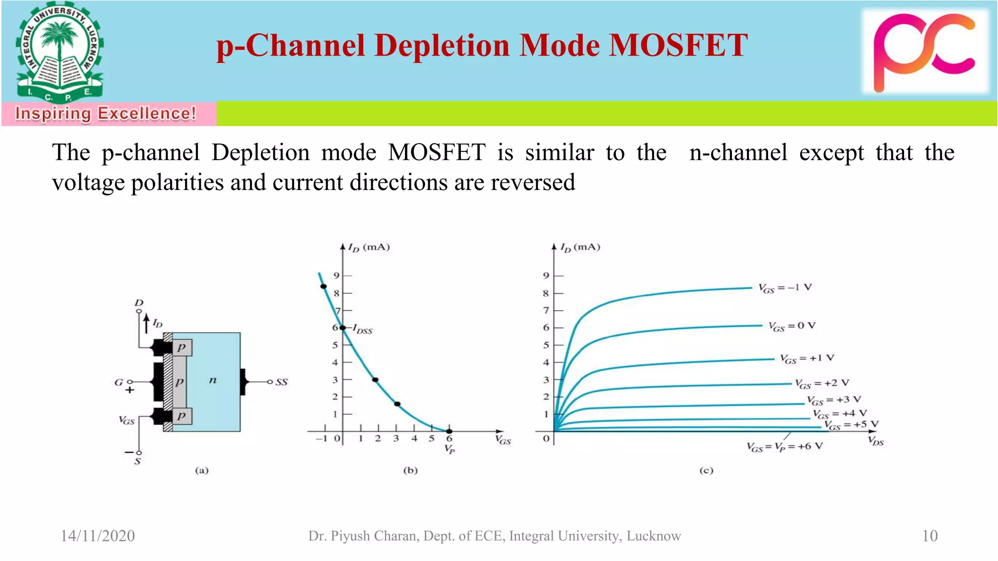
Lectures on Introduction to MOSFETs
for
Open Educational Resource
on
Electronic Devices and Circuits(EC201)
by
Dr. Piyush Charan
Assistant Professor
Department of Electronics and Communication Engg.
Integral University, Lucknow
Current Controlled vs Voltage Controlled Devices
14/11/2020 Dr. Piyush Charan, Dept. of ECE, Integral University, Lucknow 2
MOSFETs
3
• MOSFETs have characteristics similar to JFETs and additional
characteristics that make them very useful.
There are 2 types of MOSFETs:
• Depletion mode MOSFET (D-MOSFET)
• Operates in Depletion mode the same way as a JFET when VGS  0
• Operates in Enhancement mode like E-MOSFET when VGS > 0
• Enhancement Mode MOSFET (E-MOSFET)
• Operates in Enhancement mode
• IDSS = 0 until VGS > VT (threshold voltage)
14/11/2020 Dr. Piyush Charan, Dept. of ECE, Integral University, Lucknow
MOSFET Handling
4
MOSFETs are very static sensitive. Because of the very thin SiO2 layer between
the external terminals and the layers of the device, any small electrical discharge
can stablish an unwanted conduction.
Protection:
• Always transport in a static sensitive bag
• Always wear a static strap when handling MOSFETS
• Apply voltage limiting devices between the Gate and Source, such as back-to-
back Zeners to limit any transient voltage
14/11/2020 Dr. Piyush Charan, Dept. of ECE, Integral University, Lucknow
D-MOSFET Symbols
514/11/2020 Dr. Piyush Charan, Dept. of ECE, Integral University, Lucknow
Depletion Mode MOSFET Construction
6
The Drain (D) and Source (S) leads
connect to the to n-doped regions
These N-doped regions are connected
via an n-channel.
This n-channel is connected to the Gate
(G) via a thin insulating layer of SiO2
The n-doped material lies on a p-doped
substrate that may have an additional
terminal connection called SS
14/11/2020 Dr. Piyush Charan, Dept. of ECE, Integral University, Lucknow
Basic Operation
7
A D-MOSFET may be biased to operate in two modes:
the Depletion mode or the Enhancement mode
14/11/2020 Dr. Piyush Charan, Dept. of ECE, Integral University, Lucknow
D-MOSFET Depletion Mode Operation
 
 
 
2
GS
D DSS
P
V
I = I 1-
V
8
The transfer characteristics are similar to the
JFET
In Depletion Mode operation:
When VGS = 0V, ID = IDSS
When VGS < 0V, ID < IDSS
When VGS > 0V, ID > IDSS
The formula used to plot the Transfer
Curve, is:
14/11/2020 Dr. Piyush Charan, Dept. of ECE, Integral University, Lucknow
D-MOSFET Enhancement Mode Operation
 
 
 
2
GS
D DSS
P
V
I = I 1-
V
9
Enhancement Mode operation
In this mode, the transistor operates with VGS
> 0V, and ID increases above IDSS
Shockley’s equation, the formula used to plot
the Transfer Curve, still applies but VGS is
positive:
14/11/2020 Dr. Piyush Charan, Dept. of ECE, Integral University, Lucknow
10
p-Channel Depletion Mode MOSFET
The p-channel Depletion mode MOSFET is similar to the n-channel except that the
voltage polarities and current directions are reversed
14/11/2020 Dr. Piyush Charan, Dept. of ECE, Integral University, Lucknow
Enhancement Mode
MOSFET’s
Enhancement Mode MOSFET
Construction
12
The Drain (D) and Source (S) connect to the to n-
doped regions
These n-doped regions are not connected via an n-
channel without an external voltage
The Gate (G) connects to the p-doped substrate via
a thin insulating layer of SiO2
The n-doped material lies on a p-doped substrate
that may have an additional terminal connection
called SS
14/11/2020 Dr. Piyush Charan, Dept. of ECE, Integral University, Lucknow
E-MOSFET Symbols
1314/11/2020 Dr. Piyush Charan, Dept. of ECE, Integral University, Lucknow
Basic Operation
14
The Enhancement mode MOSFET
only operates in the enhancement
mode.
VGS is always positive
IDSS = 0 when VGS < VT
As VGS increases above VT, ID
increases
If VGS is kept constant and VDS is
increased, then ID saturates (IDSS)
The saturation level, VDSsat is reached.
14/11/2020 Dr. Piyush Charan, Dept. of ECE, Integral University, Lucknow
Transfer Curve
15
To determine ID given VGS:
where VT = threshold voltage or voltage at which the MOSFET turns on.
k = constant found in the specification sheet
2
D GS TI =k (V - V )
D(on)
2
GS(ON) T
I
k =
(V - V )
14/11/2020 Dr. Piyush Charan, Dept. of ECE, Integral University, Lucknow
p-Channel Enhancement Mode
MOSFETs
16
The p-channel Enhancement mode MOSFET is similar to the n-channel except that the
voltage polarities and current directions are reversed.
14/11/2020 Dr. Piyush Charan, Dept. of ECE, Integral University, Lucknow
17
Summary Table
JFET D-MOSFET E-MOSFET
14/11/2020 Dr. Piyush Charan, Dept. of ECE, Integral University, Lucknow

Unit 3 MOSFET

  • 1.
    Lectures on Introductionto MOSFETs for Open Educational Resource on Electronic Devices and Circuits(EC201) by Dr. Piyush Charan Assistant Professor Department of Electronics and Communication Engg. Integral University, Lucknow
  • 2.
    Current Controlled vsVoltage Controlled Devices 14/11/2020 Dr. Piyush Charan, Dept. of ECE, Integral University, Lucknow 2
  • 3.
    MOSFETs 3 • MOSFETs havecharacteristics similar to JFETs and additional characteristics that make them very useful. There are 2 types of MOSFETs: • Depletion mode MOSFET (D-MOSFET) • Operates in Depletion mode the same way as a JFET when VGS  0 • Operates in Enhancement mode like E-MOSFET when VGS > 0 • Enhancement Mode MOSFET (E-MOSFET) • Operates in Enhancement mode • IDSS = 0 until VGS > VT (threshold voltage) 14/11/2020 Dr. Piyush Charan, Dept. of ECE, Integral University, Lucknow
  • 4.
    MOSFET Handling 4 MOSFETs arevery static sensitive. Because of the very thin SiO2 layer between the external terminals and the layers of the device, any small electrical discharge can stablish an unwanted conduction. Protection: • Always transport in a static sensitive bag • Always wear a static strap when handling MOSFETS • Apply voltage limiting devices between the Gate and Source, such as back-to- back Zeners to limit any transient voltage 14/11/2020 Dr. Piyush Charan, Dept. of ECE, Integral University, Lucknow
  • 5.
    D-MOSFET Symbols 514/11/2020 Dr.Piyush Charan, Dept. of ECE, Integral University, Lucknow
  • 6.
    Depletion Mode MOSFETConstruction 6 The Drain (D) and Source (S) leads connect to the to n-doped regions These N-doped regions are connected via an n-channel. This n-channel is connected to the Gate (G) via a thin insulating layer of SiO2 The n-doped material lies on a p-doped substrate that may have an additional terminal connection called SS 14/11/2020 Dr. Piyush Charan, Dept. of ECE, Integral University, Lucknow
  • 7.
    Basic Operation 7 A D-MOSFETmay be biased to operate in two modes: the Depletion mode or the Enhancement mode 14/11/2020 Dr. Piyush Charan, Dept. of ECE, Integral University, Lucknow
  • 8.
    D-MOSFET Depletion ModeOperation       2 GS D DSS P V I = I 1- V 8 The transfer characteristics are similar to the JFET In Depletion Mode operation: When VGS = 0V, ID = IDSS When VGS < 0V, ID < IDSS When VGS > 0V, ID > IDSS The formula used to plot the Transfer Curve, is: 14/11/2020 Dr. Piyush Charan, Dept. of ECE, Integral University, Lucknow
  • 9.
    D-MOSFET Enhancement ModeOperation       2 GS D DSS P V I = I 1- V 9 Enhancement Mode operation In this mode, the transistor operates with VGS > 0V, and ID increases above IDSS Shockley’s equation, the formula used to plot the Transfer Curve, still applies but VGS is positive: 14/11/2020 Dr. Piyush Charan, Dept. of ECE, Integral University, Lucknow
  • 10.
    10 p-Channel Depletion ModeMOSFET The p-channel Depletion mode MOSFET is similar to the n-channel except that the voltage polarities and current directions are reversed 14/11/2020 Dr. Piyush Charan, Dept. of ECE, Integral University, Lucknow
  • 11.
  • 12.
    Enhancement Mode MOSFET Construction 12 TheDrain (D) and Source (S) connect to the to n- doped regions These n-doped regions are not connected via an n- channel without an external voltage The Gate (G) connects to the p-doped substrate via a thin insulating layer of SiO2 The n-doped material lies on a p-doped substrate that may have an additional terminal connection called SS 14/11/2020 Dr. Piyush Charan, Dept. of ECE, Integral University, Lucknow
  • 13.
    E-MOSFET Symbols 1314/11/2020 Dr.Piyush Charan, Dept. of ECE, Integral University, Lucknow
  • 14.
    Basic Operation 14 The Enhancementmode MOSFET only operates in the enhancement mode. VGS is always positive IDSS = 0 when VGS < VT As VGS increases above VT, ID increases If VGS is kept constant and VDS is increased, then ID saturates (IDSS) The saturation level, VDSsat is reached. 14/11/2020 Dr. Piyush Charan, Dept. of ECE, Integral University, Lucknow
  • 15.
    Transfer Curve 15 To determineID given VGS: where VT = threshold voltage or voltage at which the MOSFET turns on. k = constant found in the specification sheet 2 D GS TI =k (V - V ) D(on) 2 GS(ON) T I k = (V - V ) 14/11/2020 Dr. Piyush Charan, Dept. of ECE, Integral University, Lucknow
  • 16.
    p-Channel Enhancement Mode MOSFETs 16 Thep-channel Enhancement mode MOSFET is similar to the n-channel except that the voltage polarities and current directions are reversed. 14/11/2020 Dr. Piyush Charan, Dept. of ECE, Integral University, Lucknow
  • 17.
    17 Summary Table JFET D-MOSFETE-MOSFET 14/11/2020 Dr. Piyush Charan, Dept. of ECE, Integral University, Lucknow