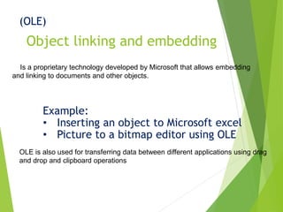
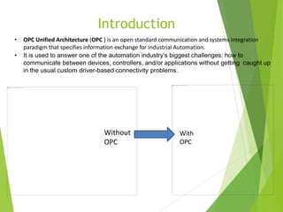
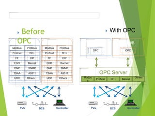
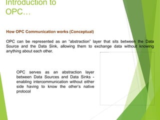
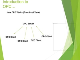
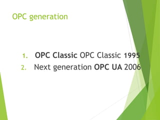
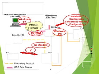
OPC
OLE for Process Control (OPC)
Object linking and embedding
(OLE)
Is a proprietary technology developed by Microsoft that allows embedding
and linking to documents and other objects.
Example:
• Inserting an object to Microsoft excel
• Picture to a bitmap editor using OLE
OLE is also used for transferring data between different applications using drag
and drop and clipboard operations
Introduction
• OPC Unified Architecture (OPC ) is an open standard communication and systems integration
paradigm that specifies information exchange for industrial Automation.
• It is used to answer one of the automation industry’s biggest challenges: how to
communicate between devices, controllers, and/or applications without getting caught up
in the usual custom driver-based connectivity problems.
Without
OPC
With
OPC
Modbus Profibus
Profinet DH+
FF CIP
EGD Bacnet
DNP SNMP
TSAA AS511
UDC Others…
HMI #A HMI #B
Modbus Profibus
Profinet DH+
FF CIP
EGD Bacnet
DNP SNMP
TSAA AS511
UDC Others…
 With OPC Before
OPC
DCS ControllerPLC
HMI #A
OPC
HMI #B
OPC
DCS ControllerPLC
Modbu
s
OPC Server
Profinet DH+ Bacnet
Others
…
Introduction to
OPC…
How OPC Communication works (Conceptual)
OPC can be represented as an “abstraction” layer that sits between the Data
Source and the Data Sink, allowing them to exchange data without knowing
anything about each other.
OPC serves as an abstraction layer
between Data Sources and Data Sinks -
enabling intercommunication without either
side having to know the other’s native
protocol
Introduction to
OPC…
How OPC Works (Functional View)
OPC Client
OPC Server
OPC Client OPC Client
OPC Client
History
• 1990 Microsoft’s Microsoft’s COM and DCOM
• 1995 Automation vendors form a task force to develop a standard for
data access based on COM and DCOM, and call it OPC(Microsoft Object
Linking & Embedding) for Process Control.
• 2001 OPC Historical Data Access (OPC HDA).
• 2006 OPC UA version came into Picture.
OPC UA version came into Picture.
OPC classic.
OPC generation
1. OPC Classic OPC Classic 1995
2. Next generation OPC UA 2006
PLC
HMI Application
(OPC Client)
OPC Server
Proprietary Protocol
OPC Data Access
Embedded HMI
No Standard
PLC
?
DCOM
Installation
Configuration
Consistence with PLC
Configuration
PLC
MES and/or HMI Application
(OPC Client)
Windows
PC
Windows
PC
9
Internet
Firewalls
OPC Classic
(Object Linking & Embedding for Process Control)
OPC
ServerWhat is an OPC Server?
An OPC Server is a software application, a “standardized” driver, specifically written
to comply with one or more OPC specifications. The word “server” in “OPC Server”
does not refer to the type of computer being used but instead reflects its
relationship with its OPC counterpart, the OPC Client.
The OPC server is a software program that converts the hardware communication
protocol used by a PLC into the OPC protocol. The OPC client software is any
program that needs to connect to the hardware, such as an HMI . The OPC client
uses the OPC server to get data from or send commands to the hardware.
OPC
Server…
What Do OPC Servers Do?
OPC Servers are connectors that may be thought of as translators between the
OPC world and a Data Source’s native communication protocol or interface. Since
OPC is bi-directional, this means OPC Servers can both read-from and write-to a
Data Source. The OPC Client/OPC Server relationship is a Master/Slave one
which means one OPC Server will only transfer data to/from a Data Source if an
OPC Client commands it to.
OPC
Clients
What is an OPC Client?
An OPC client is software written to communicate with OPC connectors. It uses
messaging defined by a specific OPC Foundation specification.
Benefits of OPC
Custom Drivers: Every end-to-end connection required a custom driver to
facilitate communications between specific endpoints. For example, if an HMI
needed to communicate with a PLC, it required a custom HMI driver written for the
specific protocol used by the PLC. If this PLC data was to be histories, the
historian required its own driver because the HMI’s custom driver could only be
used to communicate with the HMI, not the historian. If a custom driver for the
specific endpoints was not available, data communications were difficult and
expensive to establish.
OPC eliminates the need for custom drivers between each new application and
Data Source.
Complex Integration: The use of custom drivers between every endpoint meant
that even a small number of devices and applications quickly involved the use of
many drivers. The same HMI running on multiple computers, all communicating
with the same device, required multiple installations and configurations of the same
driver on each computer. If the HMIs communicated with additional devices, each
HMI required its own set of custom drivers for each of the devices. This created a
version maintenance nightmare.
Using OPC greatly simplifies integration because once an OPC Connector for a
particular Data Source is configured, all OPC-enabled applications can start sharing
data with that Data Source with no concern for additional custom drivers.
Benefits of OPC
Device and Controller Loading: Each driver establishes its own connection to the
device or controller that it is designed to communicate with. Given the large number of
custom drivers being used in a typical installation, the controller was often bombarded
by many requests for the same information from every application that it needed to
communicate with. In addition, many devices could only accept a limited number of
simultaneous connections. If the number of drivers trying to connect to a device
exceeded the number of connections it had, further workarounds were needed.
Using OPC Traffic, and hence device loading, is greatly reduced by using OPC
Connectors because a single Device-specific OPC connector requires only a single
connection to the Data Source while simultaneously communicating with many
applications
Benefits of OPC
Obsolescence of Legacy Infrastructure: As vendors release new products they
eventually stop supporting older ones. When a new version of an HMI comes out, it
may require its own set of device drivers that sometimes may no longer support
communications with a device the previous version of the HMI supported.
OPC extends the useful life of legacy systems because once an OPC connector for
a legacy system is configured, it allows any OPC-enabled application (most are) to
communicate with the legacy system regardless of whether the application natively
supports communication with the legacy system or not. Thus, OPC allows the
newest applications to continue communicating with the oldest systems.
Benefits of OPC
Principle of OPC UA
• Unified Access
• Access via Firewalls and across the Internet
• Reliability
• Platform Independence
Facts
• OPC UA is NOT A PROTOCOL
• OPC UA is not Replacement of SCADA system
• OPC UA is a CLIENT SERVER architecture
Architecture
The fundamental components of OPC Unified Architecture are transport mechanisms and data modeling.
The transport defines different mechanisms optimized for different use cases. The first version of OPC UA is defining an optimized binary
TCP protocol for high performance intranet communication as well as a mapping to accepted internet standards like Web Services, XML, and
HTTP for firewall-friendly internet communication. Both transports are using the same message-based security model known from Web
Services. The abstract communication model does not depend on a specific protocol mapping and allows adding new protocols in the future.
The data modeling defines the rules and base building blocks necessary to expose an information model with OPC UA. It defines also the
entry points into the address space and base types used to build a type hierarchy. This base can be extended by information models building
on top of the abstract modeling concepts. In addition, it defines some enhanced concepts like describing state machines used in different
information models.
The UA Services are the interface between servers as supplier of an information model and clients as consumers of that information model.
The Services are defined in an abstract manner. They are using the transport mechanisms to exchange the data between client and server.
This basic concept of OPC UA enables an OPC UA client to access the smallest pieces of data without the need to understand the whole
model exposed by complex systems. OPC UA clients also understanding specific models can use more enhanced features defined for
special domains and use cases. The following figure shows the different layers of information models defined by OPC, by other
organizations, or by vendors.
To cover all successful features known from Classic OPC, information models for the domain of process information are
defined by OPC UA on top of the base specifications. DA defines automation-data-specific extensions such as the modeling of
analog or discrete data and how to expose quality of service. All other DA features are already covered by the base. Alarm &
Conditions (AC) specifies an advanced model for process alarm management and condition monitoring. Historical Access
(HA) defines the mechanisms to access historical data and historical events. Programs (Prog) specifies a mechanism to start,
manipulate, and monitor the execution of programs.
Other organizations can built their models on top of the UA base or on top of the OPC information model, exposing their
specific information via OPC UA. Examples for standards already working on mappings to OPC UA are Field Device
Integration (FDI) combining Electronic Device Description Language (EDDL), and Field Device Tool (FDT) both used to
describe, to configure, and to monitor devices and PLCopen, a standard for PLC programming languages.
Additional vendor-specific information models will be defined using directly the UA base, the OPC models, or other OPC-UA-
based information models.
To continue the OPC introduction you can read OPC UA Specifications.
Information model
Services
Object Model
Mainframe
Portables
Server
Desktop
PC
Server
Cluster
Embedded
Systems
Controllers
Standard
internet
protocols allow
cross-platform
communication
Multiple UAAPIs
• C/C++
• JAVA
• Microsoft .NET
Yokogawa Users Conference 2013
Asia Pacific . KLCC . Malaysia Let’s build a sustai
OPC
Client
OPC
Server
OPC
Client
OPC
Server
OPC
Server
OPC
Client
Office Network
Milliseconds
Plant Information Network
Control Network
Time Frame
Hours
OPC
Client
Internet
Requirement Gap
S.Security
D Data size
T.Time frame
P Platform
Eliminate boundaries for single solution from Embedded to
Enterprise
Bytes
Data Size
K Bytes
Classic
OPC
Yokogawa Users Conference 2013
Asia Pacific . KLCC . Malaysia Let’s build a sustai
Plant
Servers
Other
Computing
Devices
Network
Gateway
Other Data
HiwayBoxes
Multifunction
Controller
Extended
Controller
Basic
Controller
Advanced
Multifunction
Controller
LocalProcessors
Transmitters
CONTROL NETWORK
Application
Module
History
Module
PLANT INFORMATION NETWORK - Ethernet
Personal Computer
NetworkManager
ControlStations
Archive
Replay Module
PLC
Gateway
Other
Subsystems
PLC
Subnetwork
Subnetwork Gateway Network
Interface
Module
LogicManager
Process
Manager
Advanced
Process
Manager
Additional
CN ModulesFiberOptics
ControlNetwork
Extenders
Area Servers Plant
Network
Modules
Network
Gateway
The factory floor is no longer an island
OFFICE NETWORK - Ethernet
ERP
Systems
MES
Systems
Managers
PC Home PC
InternetConnection
with FirewallVPN
Connection
Remote Offices
Firewall
Microchip
Desktop PC
Smartphone
PLC/Controller
Laptop
Enterprise Servers
Tablet
CE

OPC OLE for Process Control (OPC)

  • 1.
    OPC OLE for ProcessControl (OPC)
  • 2.
    Object linking andembedding (OLE) Is a proprietary technology developed by Microsoft that allows embedding and linking to documents and other objects. Example: • Inserting an object to Microsoft excel • Picture to a bitmap editor using OLE OLE is also used for transferring data between different applications using drag and drop and clipboard operations
  • 3.
    Introduction • OPC UnifiedArchitecture (OPC ) is an open standard communication and systems integration paradigm that specifies information exchange for industrial Automation. • It is used to answer one of the automation industry’s biggest challenges: how to communicate between devices, controllers, and/or applications without getting caught up in the usual custom driver-based connectivity problems. Without OPC With OPC
  • 4.
    Modbus Profibus Profinet DH+ FFCIP EGD Bacnet DNP SNMP TSAA AS511 UDC Others… HMI #A HMI #B Modbus Profibus Profinet DH+ FF CIP EGD Bacnet DNP SNMP TSAA AS511 UDC Others…  With OPC Before OPC DCS ControllerPLC HMI #A OPC HMI #B OPC DCS ControllerPLC Modbu s OPC Server Profinet DH+ Bacnet Others …
  • 5.
    Introduction to OPC… How OPCCommunication works (Conceptual) OPC can be represented as an “abstraction” layer that sits between the Data Source and the Data Sink, allowing them to exchange data without knowing anything about each other. OPC serves as an abstraction layer between Data Sources and Data Sinks - enabling intercommunication without either side having to know the other’s native protocol
  • 6.
    Introduction to OPC… How OPCWorks (Functional View) OPC Client OPC Server OPC Client OPC Client OPC Client
  • 8.
    History • 1990 Microsoft’sMicrosoft’s COM and DCOM • 1995 Automation vendors form a task force to develop a standard for data access based on COM and DCOM, and call it OPC(Microsoft Object Linking & Embedding) for Process Control. • 2001 OPC Historical Data Access (OPC HDA). • 2006 OPC UA version came into Picture. OPC UA version came into Picture. OPC classic.
  • 9.
    OPC generation 1. OPCClassic OPC Classic 1995 2. Next generation OPC UA 2006
  • 13.
    PLC HMI Application (OPC Client) OPCServer Proprietary Protocol OPC Data Access Embedded HMI No Standard PLC ? DCOM Installation Configuration Consistence with PLC Configuration PLC MES and/or HMI Application (OPC Client) Windows PC Windows PC 9 Internet Firewalls
  • 14.
    OPC Classic (Object Linking& Embedding for Process Control)
  • 15.
    OPC ServerWhat is anOPC Server? An OPC Server is a software application, a “standardized” driver, specifically written to comply with one or more OPC specifications. The word “server” in “OPC Server” does not refer to the type of computer being used but instead reflects its relationship with its OPC counterpart, the OPC Client. The OPC server is a software program that converts the hardware communication protocol used by a PLC into the OPC protocol. The OPC client software is any program that needs to connect to the hardware, such as an HMI . The OPC client uses the OPC server to get data from or send commands to the hardware.
  • 16.
    OPC Server… What Do OPCServers Do? OPC Servers are connectors that may be thought of as translators between the OPC world and a Data Source’s native communication protocol or interface. Since OPC is bi-directional, this means OPC Servers can both read-from and write-to a Data Source. The OPC Client/OPC Server relationship is a Master/Slave one which means one OPC Server will only transfer data to/from a Data Source if an OPC Client commands it to.
  • 17.
    OPC Clients What is anOPC Client? An OPC client is software written to communicate with OPC connectors. It uses messaging defined by a specific OPC Foundation specification.
  • 18.
    Benefits of OPC CustomDrivers: Every end-to-end connection required a custom driver to facilitate communications between specific endpoints. For example, if an HMI needed to communicate with a PLC, it required a custom HMI driver written for the specific protocol used by the PLC. If this PLC data was to be histories, the historian required its own driver because the HMI’s custom driver could only be used to communicate with the HMI, not the historian. If a custom driver for the specific endpoints was not available, data communications were difficult and expensive to establish. OPC eliminates the need for custom drivers between each new application and Data Source.
  • 19.
    Complex Integration: Theuse of custom drivers between every endpoint meant that even a small number of devices and applications quickly involved the use of many drivers. The same HMI running on multiple computers, all communicating with the same device, required multiple installations and configurations of the same driver on each computer. If the HMIs communicated with additional devices, each HMI required its own set of custom drivers for each of the devices. This created a version maintenance nightmare. Using OPC greatly simplifies integration because once an OPC Connector for a particular Data Source is configured, all OPC-enabled applications can start sharing data with that Data Source with no concern for additional custom drivers. Benefits of OPC
  • 20.
    Device and ControllerLoading: Each driver establishes its own connection to the device or controller that it is designed to communicate with. Given the large number of custom drivers being used in a typical installation, the controller was often bombarded by many requests for the same information from every application that it needed to communicate with. In addition, many devices could only accept a limited number of simultaneous connections. If the number of drivers trying to connect to a device exceeded the number of connections it had, further workarounds were needed. Using OPC Traffic, and hence device loading, is greatly reduced by using OPC Connectors because a single Device-specific OPC connector requires only a single connection to the Data Source while simultaneously communicating with many applications Benefits of OPC
  • 21.
    Obsolescence of LegacyInfrastructure: As vendors release new products they eventually stop supporting older ones. When a new version of an HMI comes out, it may require its own set of device drivers that sometimes may no longer support communications with a device the previous version of the HMI supported. OPC extends the useful life of legacy systems because once an OPC connector for a legacy system is configured, it allows any OPC-enabled application (most are) to communicate with the legacy system regardless of whether the application natively supports communication with the legacy system or not. Thus, OPC allows the newest applications to continue communicating with the oldest systems. Benefits of OPC
  • 22.
    Principle of OPCUA • Unified Access • Access via Firewalls and across the Internet • Reliability • Platform Independence
  • 23.
    Facts • OPC UAis NOT A PROTOCOL • OPC UA is not Replacement of SCADA system • OPC UA is a CLIENT SERVER architecture
  • 24.
  • 25.
    The fundamental componentsof OPC Unified Architecture are transport mechanisms and data modeling. The transport defines different mechanisms optimized for different use cases. The first version of OPC UA is defining an optimized binary TCP protocol for high performance intranet communication as well as a mapping to accepted internet standards like Web Services, XML, and HTTP for firewall-friendly internet communication. Both transports are using the same message-based security model known from Web Services. The abstract communication model does not depend on a specific protocol mapping and allows adding new protocols in the future. The data modeling defines the rules and base building blocks necessary to expose an information model with OPC UA. It defines also the entry points into the address space and base types used to build a type hierarchy. This base can be extended by information models building on top of the abstract modeling concepts. In addition, it defines some enhanced concepts like describing state machines used in different information models. The UA Services are the interface between servers as supplier of an information model and clients as consumers of that information model. The Services are defined in an abstract manner. They are using the transport mechanisms to exchange the data between client and server. This basic concept of OPC UA enables an OPC UA client to access the smallest pieces of data without the need to understand the whole model exposed by complex systems. OPC UA clients also understanding specific models can use more enhanced features defined for special domains and use cases. The following figure shows the different layers of information models defined by OPC, by other organizations, or by vendors. To cover all successful features known from Classic OPC, information models for the domain of process information are defined by OPC UA on top of the base specifications. DA defines automation-data-specific extensions such as the modeling of analog or discrete data and how to expose quality of service. All other DA features are already covered by the base. Alarm & Conditions (AC) specifies an advanced model for process alarm management and condition monitoring. Historical Access (HA) defines the mechanisms to access historical data and historical events. Programs (Prog) specifies a mechanism to start, manipulate, and monitor the execution of programs. Other organizations can built their models on top of the UA base or on top of the OPC information model, exposing their specific information via OPC UA. Examples for standards already working on mappings to OPC UA are Field Device Integration (FDI) combining Electronic Device Description Language (EDDL), and Field Device Tool (FDT) both used to describe, to configure, and to monitor devices and PLCopen, a standard for PLC programming languages. Additional vendor-specific information models will be defined using directly the UA base, the OPC models, or other OPC-UA- based information models. To continue the OPC introduction you can read OPC UA Specifications.
  • 26.
  • 27.
  • 28.
  • 29.
  • 30.
    Yokogawa Users Conference2013 Asia Pacific . KLCC . Malaysia Let’s build a sustai OPC Client OPC Server OPC Client OPC Server OPC Server OPC Client Office Network Milliseconds Plant Information Network Control Network Time Frame Hours OPC Client Internet Requirement Gap S.Security D Data size T.Time frame P Platform Eliminate boundaries for single solution from Embedded to Enterprise Bytes Data Size K Bytes Classic OPC
  • 31.
    Yokogawa Users Conference2013 Asia Pacific . KLCC . Malaysia Let’s build a sustai Plant Servers Other Computing Devices Network Gateway Other Data HiwayBoxes Multifunction Controller Extended Controller Basic Controller Advanced Multifunction Controller LocalProcessors Transmitters CONTROL NETWORK Application Module History Module PLANT INFORMATION NETWORK - Ethernet Personal Computer NetworkManager ControlStations Archive Replay Module PLC Gateway Other Subsystems PLC Subnetwork Subnetwork Gateway Network Interface Module LogicManager Process Manager Advanced Process Manager Additional CN ModulesFiberOptics ControlNetwork Extenders Area Servers Plant Network Modules Network Gateway The factory floor is no longer an island OFFICE NETWORK - Ethernet ERP Systems MES Systems Managers PC Home PC InternetConnection with FirewallVPN Connection Remote Offices Firewall
  • 32.