1. UNIT 2
PART A
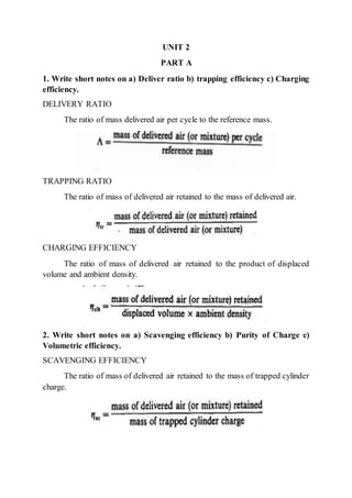
1. Write short notes on a) Deliver ratio b) trapping efficiency c) Charging
efficiency.
DELIVERY RATIO
The ratio of mass delivered air per cycle to the reference mass.
TRAPPING RATIO
The ratio of mass of delivered air retained to the mass of delivered air.
CHARGING EFFICIENCY
The ratio of mass of delivered air retained to the product of displaced
volume and ambient density.
2. Write short notes on a) Scavenging efficiency b) Purity of Charge c)
Volumetric efficiency.
SCAVENGING EFFICIENCY
The ratio of mass of delivered air retained to the mass of trapped cylinder
charge.
2. PURITY OF CHARGE
The ratio of mass of air trapped cylinder charge to the mass of trapped
cylinder charge.
3. Describe about actual scavenging process.
Actual Scavenging Processes; Several methods have been developed for
determining what occurs in actual Cylinder scavenging processes. Accurate
measurement of scavenging efficiency is difficult due to the problem of
measuring the trapped air mass. The physical variables were scaled to maintain
the same values of the appropriate dimensionless numbers for the liquid
analogy flow and the real engine flow. The density of the liquid representing
air (which is dark) was twice the density of the liquid representing burned
gas (which is clear).
The short-circuiting fluid flows directly between the scavenge ports and
the exhaust ports above them. Since this damming-up of the inflowing fresh
air back toward the exhaust ports continues, short-circuiting losses will also
continue. Out flowing fluid composition measurements from this model study
of a Seltzer two-stroke loop-scavenged diesel engine confirm this sequence
of events. At 24 crank angle degrees after the onset of, scavenging, fresh air due
to short-circuiting was detected in the exhaust. For two-stroke cycle spark
ignition engines, which use crankcase pumping, delivery ratios vary between
about 0.5 and 0.8.
3. 4. Clearly explain the role of compressors and their types in Gas exchange
process.
Practical mechanical supercharging devices can be classified into: (1)
sliding vane compressors, (2) rotary compressors, and (3) centrifugal
compressors. The first two types are positive displacement compressors;the last
type is an aerodynamic compressor. Fourdifferent types ofpositive displacement
compressors are illustrated.
In the sliding vane compressor, deep slots are cut into the rotor to
accommodate thin vanes which are free to move radially. The rotor is mounted
eccentrically in the housing. As the rotor rotates, the centrifugal forces acting on
the vanes force them outward against the housing, thereby dividing the
Crescent-shaped space into several compartments. The volumetric efficiency can
vary between 0.6 and 0.9 depending on the size ofthe machine, the quality of the
design, and the method of lubrication and cooling employed. The displaced
volume V, is given by
4. Here r is the rotor radius, E the eccentricity, and 1 the axial length of the
compressor. The mass flow rate parameter is
The mass flow rate at constant speed depends on the pressure ratio only
through its (weak) effect on volumetric efficiency. The isentropic efficiency is
relatively low. A centrifugal compressor is primarily used to boost inlet air or
mistune density coupled with an exhaust-driven turbine in a turbocharger. It is a
single stage radial flow device, well suited to the high mass flow rates at the
relatively low pressure ratios (up to about 3.5) required by the engine.
5. Clearly explain the role of Turbines and their types in Gas exchange
process.
Turbines: The turbocharger turbine is driven by the energy available in
the engine exhaust. The ideal energy available is shown in Fig. 6-48. It consists
of the blowdown work transfer produced by expanding the gas in the cylinder at
exhaust valve opening to atmospheric pressure (area abc) and (for the four-stroke
cycle engine) the work done by the piston displacing the gases remaining in the
cylinder after blowdown (area cdej). The reciprocating internal combustion
engine is inherently an unsteady pulsating flow device. Turbines can be designed
5. to accept such an unsteady flow, but they operate more efficiently under steady
flow conditions. In practice, two approach for recovering a fraction of the
available exhaust energy are commonly used; constant-pressure turbocharging
and pulse turbocharging.
The disadvantage of this approach is that it does not make full use of the
high kinetic energy of the gases leaving the exhaust port; the losses inherent in
the mixing of this high-velocity gas with a large volume of low-velocity gas
cannot be recovered. Two types of turbines are used in turbochargers: radial and
axial flow turbines. The radial flow turbine is similar in appearance to the
centrifugal compressor;however, the flow is radially inward not outward. Radial
flow turbines are normally used in automotive or truck applications. Larger
engines-locomotive stationary, or marine-use axial flow turbines.
Many different types of plots have been used to define radial flow turbine
characteristics constant corrected speed and efficiency on a plot of pressure ratio
versus corrected mass flow rate. As flow rate increases at a given speed, it
asymptotically approaches a limit correspondingto the flow becoming choked in
the stator nozzle blades or the rotor. This turbine consists of an annular flow
passage, a single row of nozzles or stator blades, and a rotations blade ring.
6. 6. Shortly explain Turbo chargers and super chargers.
The maximum power a given engine can deliver is limited by the amount
of fuel that can be burned efficiency inside the engine cylinder. This is limited by
the amount of air that is introduced into each cylinder each cycle. If the inducted
air is compressed to ahigher density than ambient, prior to entry into the cylinder,
the maximum power an engine of fixed dimensions can deliver will be increased.
This is the primary purpose of surcharging;
The term supercharging refers to increasing the air (or mixture) density by
increasing its pressure prior to entering the engine cylinder. Three basic methods
are used to accomplish this. The first is mechanical supercharging separate pump
orblower orcompressor,usually driven bypowertaken from the engine, provides
the compressed air.
The second method is turbocharging, where turbocharger-a compressor
and turbine on a single shaft-is used to boost the inlet air (or mixture) density.
Energy available in the engine's exhaust stream is used to drive the turbocharger
turbine which drives the turbocharger compressor which raises the inlet fluid
density prior to entry to each engine cylinder. Third method-pressure wave
supercharging-uses wave action in the intake and exhaust systems to compress
the intake mixture. Turbo compounding, i.e., use of a second turbine in the
exhaust directly geared to the engine driveshaft (Fig. 6-37e), is an alternative
method of increasing engine power (and efficiency). Charge cooling with a heat
exchanger (often called an after cooler or intercooler) after compression, prior to
entry to the cylinder, can be used to increase further the air or mixture density.
7. Give details about wave compression devices.
Pressure wave superchargers make use of the fact that if two fluids having
different pressures are brought into direct contact in long narrow channels,
equalization of pressure occurs faster than mixing. There is no contact between
the rotorand the casing, but the gaps are kept small to minimize leakage. The belt
drive merely overcomes friction and maintains the rotor at a speed proportional
to engine speed (usually 4 or 5 times faster): it provides no compression work.
The other casing (the gas casing) connects the high-pressure engine exhaust gas.
Fluid can flow into and out of the rotorchannels through these ports. Theexhaust
gas inlet port is made small enough to cause a significant pressure rise in the
exhaust manifold (e.g., 2 atm) when the engine is operated at its rated power.
7. The compressed air behind the wave occupies less space so the high
pressure exhaust gas moves into the channel as indicated by the dotted line. This
line is the boundary between the two fluids. As this wave (1) reaches the left end,
the channel is opened and compressed air flows into the engine inlet duct (A-
HP).As a result, the compressed air leaving the cell on the left has a higher
pressure than the driving gas on the right. As this wave (2) arrives at the right-
hand side, the high-pressure gas (G-HP) channel closes. The cell's contents are
still at a higher pressure than the low pressure in the exhaust gas duct. When the
right-hand end of the cell reaches this duct, the cell's contents expand into the
exhaust. The speed of these pressure waves is the local sound speed and is a
function of local gas temperature only. Thus, the above process will only work
properly for a given exhaust gas temperature at a particular cell speed.
The apparent compressorperformancemap of a Comprex when connected
to a small three-cylinder diesel engine. Note that the map depends on the engine
to which the device is coupled because the exhaust gas expansion process and
fresh air compressionprocess occurwithin the same rotor. The volume flaw rate
is the net air: it is the total air flow into the device less the scavenging air flow.
The values of isentropic efficiency are comparable to those of mechanical and
aerodynamic compressors.
8. 8. Briefly explain about flow through ports.
The importance of the intake and exhaust ports to the proper functioning
of the two-stroke cycle scavenging process is clear from the discussion in Sec.
6.6. The crank angle at which the ports open, the size, number, geometry, and
location ofthe ports around the cylinder circumference, and the direction and
9. velocity of the jets issuing from the ports into the cylinder all affect the
scavenging flow.
Illustrates the flow patterns expected downstream of piston- controlled
inlet ports. Forsmall openings, the flow remains attached to the port Walls. For
fully open ports with sharp corners the flow detaches at the upstream corner
The discharge coefficient decreases as the jet tangential inclination increases. The
jet angle and the port angle can deviate significantly from each other depending
on the details of the port design and the open fraction.
PART B
1. With sketchesexplain the Gas exchange in inlet and exhaust processesofa
four stroke cycle.
In a spark-ignition engine, the intake system typically consists of an air
filter, a carburettor and throttle or fuel injector and throttle or throttle with
individual fuel injectors in each intake port, and intake manifold. During the
induction process, pressure losses occur as the mixture passes through or by
each of these components. There is an additional pressure drop across the
intake port and valve. The exhaust system typically consists of an exhaust
manifold, exhaust pipe, often a catalytic converter for emission control, and a-
muffler or silencer. Figure 6-1 illustrates the intake and exhaust gas flow
processes in a conventional spark ignition engine. The drop in pressure along
the intake system depends on engine speed, the flow resistance of the
elements in the system, the cross-sectional area through which the fresh
charge moves, and the charge density. The terms blow down and
displacement are used to denote these two phases of the exhaust process
10. Typically, the exhaustvalvecloses 15 to 30" after TC and the inlet valveopens
10 to 20" before TC.
The advantage of valve overlap occurs at high engine speeds when the
longer valve-openperiods improve volumetric efficiency. Asthe piston moves
past TC and the cylinder pressure falls below the intake pressure, gas flows
from the intake into the cylinder. The intake valve remain open until 50 to
70" after BC so that fresh chargemay continue to flow into the cylinder after
BC.
11. 2. With the aid oftwo stroke engine configurations explainaboutscavenging
process
In two-stroke cycle engines, each outward stroke of the piston is a power
stroke. To achieve this operating cycle, the fresh charge must be supplied to
the engine cylinder at a high-enough pressure to displace the burned gases
from the previous cycle. Raising the pressure of the intake mixture is done in a
separate pump or blower orcompressor. Theoperation of clearing the cylinder of
burned gases and filling it with fresh mixture (or air) the combined intake and
exhaust process-is called scavenging process. The different categories of two-
stroke cycle scavenging flows and the (portand valve) arrangements that produce
them are illustrated. Scavenging arrangements are classified into: (a) cross-
scavenged, (b) loop-scavenged, and (c) uniflow-scavenged configuration.
Despite the different flow patterns obtained with each cylinder geometry,
the general operating principles are similar. Air in a diesel, or fuel-air mixture
in a spark-ignition engine, must be supplied to the inlet ports at a pressurehigher
than the exhaust system pressure.
Initially, the pressure ratio across the exhaust valve exceeds the critical
value and the flow at the valve will be sonic. The discharge period up to the time
of the scavenging port opening is called the blowdown (or free exhaust) period.
The scavenging ports open between 60 and 40" before BC when the cylinder
pressure slightly exceeds the scavenging pump pressure.
12. 3. With neat sketchesdescribe the various supercharging andturbocharging
configurations
The maximum power a given engine can deliver is limited by the
amount of fuel that can be burned efficiently inside the engine cylinder. This is
limited by the amount of air that is introduced into each cylinder each cycle. If
the inducted air is compressed to ahigher density than ambient, prior to entry into
the cylinder, the maximum power an engine of fixed dimensions can deliver will
be increased. The term supercharging refers to increasing the air (or mixture)
density by increasing its pressure prior to entering the engine cylinder. Three
basic methods are used to accomplish this. The first is mechanical supercharging
separate pump or blower or compressor, usually driven by power taken from the
engine, provides the compressed air.
The second method is turbocharging, where turbocharger-a compressor and
turbine on a single shaft-is used to boosttheinlet air (or mixture) density. Energy
available in the engine's exhaust stream is used to drive the turbocharger turbine
which drives the turbocharger compressor which raises the inlet fluid density
prior to entry to each engine cylinder.
Basic Relationships;
Expressions for the work required to drive a blower or compressorand the
work Produced by a turbine are obtained from the first and second laws of
thermodynamics. The first law, in the form of the steady flow energy equation,
applied to a Control volume around the turbomachinery component is
Q is the heat-transfer rate into the control volume, w is the shaft work
transfer rate out of the control volume, m is the mass flow, h is the specific
enthalpy is the specific kinetic energy, and gz is the specific potential energy
(which is not important and can be omitted).
A stagnation or total enthalpy, ho can be defined as
Gas with constant specific heats, a stagnation or total temperature
13. A stagnation or total pressure is also defined: it is the pressure attained if the gas
is isentropically brought to rest; then gives the work-transfer rate as;
For a compressor, the compressor isentropic efficiency is
Since the kinetic energy at the exit of a turbocharger turbine is usually
wasted, a total-to-static turbine isentropic effciency, where the reversible
aidabatic power output is that obtained between inlet stagnation condition and
the exit static pressure, is more realistic:
It is advantageous if the operating characteristics of blowers,
compressors, and turbines can be expressed in a manner that allows easy
comparison between different designs and sizes of devices. This can be done
by describing the characteristics in terms of dimensionless numbers?' The most
important dependent performance variables are: mass flow rate m, component
isentropic efficiency q.
The total-to-total isentropic efficiency is, from Eq
14. Since cp is essentially constant for air, or fuel-air mixture, becomes
Since the process 01 to 02s is isentropic
15. 4. Highlight the importance of residual gas fractionduring compressionand
explain how it is determined.
The residual gas fraction in the cylinder during compression is
determined by the exhaust and inlet processes. Its magnitude affects volumetric
efficiency and engine performance directly, and efficiency and emissions through
its effect on working fluid thermodynamic properties. The residual gas fraction is
primarily a function of inlet and exhaust pressures, speed, compression ratio,
valve timing, and exhaust system dynamics.
16. The residual gas mass fraction x, (or burned gas fraction if EGR is used) is
usually determined by measuring the CO, concentration in a sample of gas
extracted from the cylinder during the compression stroke. Then
Residual gas measurements in a spark-ignition engine are given in Fig. 6-
19, which shows the effect of changes in speed, valve overlap, compressionratio,
and air/fuel ratio for a range of inlet manifold pressures for a 2-dm3, 88.5-mm
bore, four-cylinder engine.22The effect of variations in spark timing was
negligible.
Inlet pressure, speed, and valve overlap are the most important variables,
though the exhaust pressure also affects the residual fraction '~normal settings for
inlet valve opening (about 15" before TC) and exhaust valve closing (about 12"
after TC) provide sufficient overlap for good scavenging, but avoid excessive
backflow from the exhaust port into the cylinder.
Residual gas fractions in diesel engines are substantially lower than in SI
engines because inlet and exhaust pressures are comparable in magnitude and the
compression ratio is 2 to 3 times as large. Also, a substantial fraction of the
residual gas is air.
5. Explain the exhaust gas flow rate and temperature variation.
The exhaust gas mass flow rate and the properties of the exhaust gas vary
significantly during the exhaust process. The origin of this variation for an ideal
exhaust process is evident. The thermodynamic state (pressure, temperature, etc.)
17. of the gas in the cylinder varies continually during the exhaust blowdown phase,
until the cylinder pressure closely approaches the exhaust manifold pressure. In
the real exhaust process, the exhaust valve restricts the flow out of the cylinder,
the valve lift varies with time, and the cylinder volume changes during the
blowdown process, but the principles remain the same.
Measurements have been made of the variation in mass flow rate through
'he exhaust valve and gas temperature at the exhaust port exit during the exhaust
Process of a spark-ignition engine. Figure 6-20 shows the instantaneous mass
flow rate data at three different engine speeds.
Simple quasi-steady models of these phases give good agreement with the
data at lower engine speeds. The blowdown model shown applies orifice flow
equations to the flow across the exhaust valve using the measured cylinder
pressure and estimated gas temperature for upstream stagnation condition.
The displacement model assumes the gas in the cylinder is incompressible
as the piston moves through the exhaust stroke. As engine speed increases, the
crank angle duration of the blowdown phase increases. There is evidence of
dynamic effects occurring at the transition between the two phases.
The mass flow rate at the time of maximum piston speed during
displacement scales approximately with piston speed. As the inlet manifold
pressure is reduced below the wide-open throttle value, the proportion of the
charge which exits the cylinder during the blowdown phase decreases but the
mass flow rate during displacement remains essentially constant.
18. The exhaust gas temperature varies substantially through the exhaust
process, and decreases due to heat loss as the gas flows past the exhaust valve and
through the exhaust system. The measured cylinder pressure, calculated cylinder
gas temperature and exhaust mass flow rate, and measured gas temperature at the
exhaust port exit for a single-cylinder spark-ignition engine at mid-load and low
speed.
The gas temperature at the portexit at the start of the exhaust flow pulse is
a mixture of hotter gas which has just left the cylinder and cooler gas which left
the cylinder at the end of the previous exhaust process and has been stationary in
the exhaust port while the valve has been closed.
The effect of varying load and speed on exhaust port exit temperatures.
Increasing load (A + B -, C) increases the mass and temperature in the blowdown
pulse. Increasing speed (B-D) raises the gas temperature throughout the exhaust
process. The time available for heat transfer, which depends on engine speed and
exhaust gas flow rate, is the most critical factor.
The average exhaust gas temperature is an important quantity for
determining the performance of turbochargers, catalytic converters, and
particulate traps. The time-averaged exhaust temperature does not correspond to
the average energy of the exhaust gas because the flow rate varies substantially.
An enthalpy-averaged temperature
19. 6. Elucidate the poppet valve geometry and timing.
FLOW THROUGH VALVES
The valve, or valve and port together, is usually the most important flow
restriction in the intake and the exhaust system of four-stroke cycle engines. The
characteristics of flows through poppet valves will now be reviewed.
POPPET VALVE GEOMETRY AND TIMING:
The main geometric parameters of a poppet valve head and seat. The
proportions of typical inlet and exhaust valves and ports, relative to the valve
inner seat diameter D. The inlet port is generally circular, or nearly so, and the
cross-sectional area is no larger than is required to achieve the desired power
output. Forthe exhaust port, the importance of good valve seat and guide cooling,
with the shortestlength ofexposed valve stem, leads to a different design. Typical
valve head sizes for different shaped combustion chambers in terms of cylinder
bore B.
Typical valve timing, valve-lift profiles, and valve open areas for a four
stroke cycle spark-ignition engine. There is no universally accepted criterion for
defining valve timing points. Some are based upon a specific lift criterion. For
example, SAE defines valve timing events based on reference valve-lift points:
1. Hydraulic lifters. Opening and closing positions are the 0.15-mm
(0.006-in) valve-lift points.
2. Mechanical lifters. Valve opening and closing positions are the
points of 0.1 5-mm (0.006-in) lift plus the specified lash.
20. The instantaneous valve flow area depends on valve lift and the geometric
details of the valve head, seat, and stem. There are three separate stages to the
flow area development as valve lift increases, 14. For low valve lifts, the
minimum flow area corresponds to a frustum of a right circular cone where the
conical face between the valve and the seat, which is perpendicular to the seat,
defines the flow area. For this stage;
21. Forthe second stage, theminimum area is still the slant surfaceofa frustum
of a right circular cone, but this surface is no longer perpendicular to the valve
seat. The baseangle of the coneincreases from (90 - 8)" toward that of a cylinder,
90". Forthis stage. Intake and exhaust valve openareas correspondingto a typical
valve-lift profile are plotted versus camshaft angle. These three different flow
regimes are indicated. The maximum valve lift is normally about 12 percent of
the cylinder bore.
Inlet valve opening (IVO) typically occurs 10 to 25" BTC. Engine
performance is relatively insensitive to this timing point. It should occur
sufficiently before TC so that cylinder pressure does not dip early in the intake
stroke. Inlet valve closing (IVC) usually falls in the range 40 to 60" after BC, to
provide more time for cylinder filling under conditions where cylinder pressure
is below the intake manifold pressure at BC. IVC is one of the principal factors
that determines high-speed volumetric efficiency.
The effect of valve geometry and timing on air flow can be illustrated
conceptually by dividing the rate of change of cylinder volume by the
instantaneous minimum valve flow area to obtain a pseudoflow velocity for each
valve.