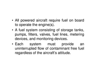
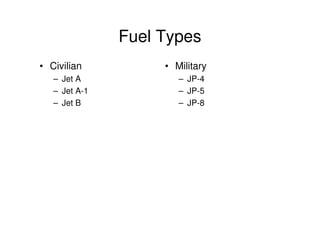
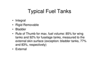
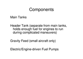
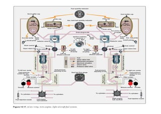
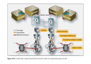
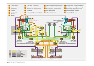
The document discusses aircraft fuel systems and engine lubrication systems. It describes the key components of an aircraft's fuel system including fuel tanks, pumps, filters and lines required to provide an uninterrupted flow of fuel to the engines. It also discusses the different types of fuels used in aircraft as well as lubrication systems which reduce friction and wear using circulating oil to lubricate engine parts.
The fuel system is designed to provide an uninterrupted flow of clean fuel from the fuel tanks to the engine. The fuel must be available to the engine under all conditions of engine power, altitude, attitude, and during all approved flight maneuvers . Fuel systems differ greatly from aircraft to aircraft due to the relative size and complexity of the aircraft in which they are installed.
Aircraft Air Conditioning And Pressurisation SystemCahit Kutay Uysal
At this presentation, I try to explain aircraft pressurization systems and air conditioning systems. I hope it will be useful source to understand aircraft systems easily.
The turbofan engine is a propulsive mechanism to combine the high thrust of a turbojet with the high efficiency of a propeller. Basically, a turbojet engine forms the core of the turbofan; the core contains the diffuser, compressor, burner, turbine, and nozzle. However, in the
turbofan engine, the turbine drives not only the compressor, but also a large fan external to the core. The fan itself is contained in a shroud that is wrapped around the core.
This PPT gives a brief explanation about the fuel system used in commercial airplanes. This includes how it's done, different ways to be done and the difficulties faced during the process.
A transport category aircraft fuel distribution subsystem consists of the pressure fueling components, defueling components, transfer system, and fuel jettison or dump system. Single-point pressure fueling at a fueling station accessible by ramp refueling trucks allows all aircraft fuel tanks to be filled with one connection of the fuel hose. Leading and trailing edge wing locations are common for these stations.
To fuel with pressure refueling, a hose nozzle is attached at the fueling station and valves to the tanks required to be filled are opened. These valves are called fueling valves or refueling valves depending upon the manufacturer’s preference. Various automatic shutoff systems have been designed to close tank fueling valves before the tanks overfill or are damaged. Gauges on the refueling panel allow refueling personnel to monitor progress.
MARINE DIESEL ENGINES & Engine in DSV.pptxSarath40652
Seminar on Marine Diesel engines with example of diesel engine used in 120m long DSV Ship. This is pure academic related. This is from an real time experience in Shipyard on Naval Ships. Very useful and Authentic information. This also gives an idea about the engine size requirement for a particular ship size & speed.
Diesel Power Plant Diesel Power Plant Diesel Power Plant Diesel Power Plant Diesel Power Plant Diesel Power Plant Diesel Power Plant Diesel Power Plant Diesel Power Plant Diesel Power Plant Diesel Power Plant Diesel Power Plant Diesel Power Plant Diesel Power Plant Diesel Power Plant Diesel Power Plant Diesel Power Plant Diesel Power Plant Diesel Power Plant Diesel Power Plant Diesel Power Plant Diesel Power Plant Diesel Power Plant Diesel Power Plant Diesel Power Plant Diesel Power Plant Diesel Power Plant Diesel Power Plant Diesel Power Plant Diesel Power Plant Diesel Power Plant Diesel Power Plant Diesel Power Plant Diesel Power Plant Diesel Power Plant Diesel Power Plant Diesel Power Plant Diesel Power Plant Diesel Power Plant Diesel Power Plant Diesel Power Plant Diesel Power Plant Diesel Power Plant Diesel Power Plant Diesel Power Plant Diesel Power Plant Diesel Power Plant Diesel Power Plant Diesel Power Plant
Proulsion I - SOLVED QUESTION BANK - RAMJET ENGINESanjay Singh
The material is only for academic purpose and for preparation of exams. Contents are copied from reference books. Not for revenue generation of any kind.
Rockets and missiles solved question bank - academic purpose onlySanjay Singh
The study material will be useful for aeronautical engineering students for preparation for their exams. It is made for academic purpose only and not for revenue generation of any kind. Rocket Propulsion Elements by Sutton is used for preparation of this QB.
Unit IV Solved Question Bank- Robotics EngineeringSanjay Singh
This Question Bank for Robotics Engineering is only for academic purpose and not for any commercial use. Students of Anna University and other Universities can use it for reference and knowledge.
Unit III - Solved Question Bank- Robotics Engineering -Sanjay Singh
This Question Bank for Robotics Engineering is only for academic purpose and not for any commercial use. Students of Anna University and other Universities can use it for reference and knowledge.
Unit v - Solved qb - Robotics EngineeringSanjay Singh
This Question Bank for Robotics Engineering is only for academic purpose and not for any commercial use. Students of Anna University and other Universities can use it for reference and knowledge.
Unit II Solved Question Bank - Robotics Engineering -Sanjay Singh
This Question Bank for Robotics Engineering is only for academic purpose and not for any commercial use. Students of Anna University and other Universities can use it for reference and knowledge.
CFD Simulation of By-pass Flow in a HRSG module by R&R Consult.pptxR&R Consult
CFD analysis is incredibly effective at solving mysteries and improving the performance of complex systems!
Here's a great example: At a large natural gas-fired power plant, where they use waste heat to generate steam and energy, they were puzzled that their boiler wasn't producing as much steam as expected.
R&R and Tetra Engineering Group Inc. were asked to solve the issue with reduced steam production.
An inspection had shown that a significant amount of hot flue gas was bypassing the boiler tubes, where the heat was supposed to be transferred.
R&R Consult conducted a CFD analysis, which revealed that 6.3% of the flue gas was bypassing the boiler tubes without transferring heat. The analysis also showed that the flue gas was instead being directed along the sides of the boiler and between the modules that were supposed to capture the heat. This was the cause of the reduced performance.
Based on our results, Tetra Engineering installed covering plates to reduce the bypass flow. This improved the boiler's performance and increased electricity production.
It is always satisfying when we can help solve complex challenges like this. Do your systems also need a check-up or optimization? Give us a call!
Work done in cooperation with James Malloy and David Moelling from Tetra Engineering.
More examples of our work https://www.r-r-consult.dk/en/cases-en/
About
Indigenized remote control interface card suitable for MAFI system CCR equipment. Compatible for IDM8000 CCR. Backplane mounted serial and TCP/Ethernet communication module for CCR remote access. IDM 8000 CCR remote control on serial and TCP protocol.
• Remote control: Parallel or serial interface.
• Compatible with MAFI CCR system.
• Compatible with IDM8000 CCR.
• Compatible with Backplane mount serial communication.
• Compatible with commercial and Defence aviation CCR system.
• Remote control system for accessing CCR and allied system over serial or TCP.
• Indigenized local Support/presence in India.
• Easy in configuration using DIP switches.
Technical Specifications
Indigenized remote control interface card suitable for MAFI system CCR equipment. Compatible for IDM8000 CCR. Backplane mounted serial and TCP/Ethernet communication module for CCR remote access. IDM 8000 CCR remote control on serial and TCP protocol.
Key Features
Indigenized remote control interface card suitable for MAFI system CCR equipment. Compatible for IDM8000 CCR. Backplane mounted serial and TCP/Ethernet communication module for CCR remote access. IDM 8000 CCR remote control on serial and TCP protocol.
• Remote control: Parallel or serial interface
• Compatible with MAFI CCR system
• Copatiable with IDM8000 CCR
• Compatible with Backplane mount serial communication.
• Compatible with commercial and Defence aviation CCR system.
• Remote control system for accessing CCR and allied system over serial or TCP.
• Indigenized local Support/presence in India.
Application
• Remote control: Parallel or serial interface.
• Compatible with MAFI CCR system.
• Compatible with IDM8000 CCR.
• Compatible with Backplane mount serial communication.
• Compatible with commercial and Defence aviation CCR system.
• Remote control system for accessing CCR and allied system over serial or TCP.
• Indigenized local Support/presence in India.
• Easy in configuration using DIP switches.
Student information management system project report ii.pdfKamal Acharya
Our project explains about the student management. This project mainly explains the various actions related to student details. This project shows some ease in adding, editing and deleting the student details. It also provides a less time consuming process for viewing, adding, editing and deleting the marks of the students.
Explore the innovative world of trenchless pipe repair with our comprehensive guide, "The Benefits and Techniques of Trenchless Pipe Repair." This document delves into the modern methods of repairing underground pipes without the need for extensive excavation, highlighting the numerous advantages and the latest techniques used in the industry.
Learn about the cost savings, reduced environmental impact, and minimal disruption associated with trenchless technology. Discover detailed explanations of popular techniques such as pipe bursting, cured-in-place pipe (CIPP) lining, and directional drilling. Understand how these methods can be applied to various types of infrastructure, from residential plumbing to large-scale municipal systems.
Ideal for homeowners, contractors, engineers, and anyone interested in modern plumbing solutions, this guide provides valuable insights into why trenchless pipe repair is becoming the preferred choice for pipe rehabilitation. Stay informed about the latest advancements and best practices in the field.
Sachpazis:Terzaghi Bearing Capacity Estimation in simple terms with Calculati...Dr.Costas Sachpazis
Terzaghi's soil bearing capacity theory, developed by Karl Terzaghi, is a fundamental principle in geotechnical engineering used to determine the bearing capacity of shallow foundations. This theory provides a method to calculate the ultimate bearing capacity of soil, which is the maximum load per unit area that the soil can support without undergoing shear failure. The Calculation HTML Code included.
Immunizing Image Classifiers Against Localized Adversary Attacksgerogepatton
This paper addresses the vulnerability of deep learning models, particularly convolutional neural networks
(CNN)s, to adversarial attacks and presents a proactive training technique designed to counter them. We
introduce a novel volumization algorithm, which transforms 2D images into 3D volumetric representations.
When combined with 3D convolution and deep curriculum learning optimization (CLO), itsignificantly improves
the immunity of models against localized universal attacks by up to 40%. We evaluate our proposed approach
using contemporary CNN architectures and the modified Canadian Institute for Advanced Research (CIFAR-10
and CIFAR-100) and ImageNet Large Scale Visual Recognition Challenge (ILSVRC12) datasets, showcasing
accuracy improvements over previous techniques. The results indicate that the combination of the volumetric
input and curriculum learning holds significant promise for mitigating adversarial attacks without necessitating
adversary training.
Aircraft and engine fuel system and engine lubrication system
1. AIRCRAFT AND ENGINE
FUEL SYSTEM AND ENGINE
LUBRICATION SYSTEM
Prof. Sanjay Singh
VMKV Engineering College, Salem
sansiaf@gmail.com
2. • All powered aircraft require fuel on board
to operate the engine(s).
• A fuel system consisting of storage tanks,
pumps, filters, valves, fuel lines, metering
devices, and monitoring devices.
• Each system must provide an
uninterrupted flow of contaminant free fuel
regardless of the aircraft’s attitude.
3. Business and Commercial Aviation
Magazine
• “An aircraft's fuel system has a more
profound effect on aircraft performance
than any other airframe system. Without
fuel, the mission inevitably comes to an
abrupt stop and, unless the flight crew is
very, very lucky, the ensuing forced
landing will cause severe or catastrophic
aircraft damage.” ~ Fred George, 6/20/06
http://www.avweek.com/avnow/news/channel_bca_story.jsp?id=news/fuel0606.xml
5. Typical Fuel Tanks
• Integral
• Rigid Removable
• Bladder
• Rule of Thumb for max. fuel volume: 85% for wing
tanks and 92% for fuselage tanks, measured to the
external skin surface (exception: bladder tanks, 77%
and 83%, respectively)
• External
6. Components
Main Tanks
Header Tank (separate from main tanks,
holds enough fuel for engines to run
during complicated maneuvers)
Gravity Feed (small aircraft only)
Electric/Engine-driven Fuel Pumps
8. Fuel Dumping Systems
• Needed to meet landing weight limits of
landing gear or runway length
• System of fuel pumps and valves
• Usually ejected from wingtips
• Sometimes from aft-most point of fuselage
• Usually designed to allow the plane to go
from max take-off weight to max landing
weight in 15 minutes or less.
11. In-Flight Refueling
• Original motivation: endurance records
• Currently used only in the military sector
• Two main types:
– Boom and Receptacle
– Probe and Drogue
http://www.answers.com/topic/aerial-refueling
12. • Since fuel load can be a significant portion
of the aircraft’s weight, a sufficiently strong
airframe must be designed.
• Varying fuel loads and shifts in weight
during manoeuvers must not negatively
affect control of the aircraft in flight.
13. Types of Aviation Fuel
• Each aircraft engine is designed to burn a
certain fuel.
• Use only the fuel specified by the manufacturer.
Mixing fuels is not permitted.
• There are two basic types of fuel used in aircraft:
- Reciprocating-engine fuel (also known as
gasoline or AVGAS) and
- Turbine-engine fuel (also known as jet fuel or
kerosene).
14. • Aviation gasoline is different from the fuel
refined for use in turbine-powered aircraft.
• AVGAS is very volatile and extremely
flammable, with a low flash point.
• Turbine fuel is a kerosene-type fuel with a
much higher flash point so it is less
flammable.
15. Important characteristics of an
aircraft fuel
• Volatility
How readily a substance changes from
liquid into a vapor.
• Vapor Lock
Vapor lock is a condition in which
AVGAS vaporizes in the fuel line or other
components between the fuel tank and the
carburetor.
16. • Carburetor Icing
As fuel vaporizes, it draws energy from
its surroundings to change state from a
liquid to a vapor. This can be a problem if
water is present.
17.
18. Small Single-Engine Aircraft Fuel
Systems
• Small single-engine aircraft fuel systems vary
depending on factors, such as tank location and
method of metering fuel to the engine.
• A high-wing aircraft fuel system can be designed
differently from one on a low-wing aircraft.
• An aircraft engine with a carburetor has a
different fuel system than one with fuel injection.
19. Fuel Pumps
• Fuel pumps are part of most aircraft fuel systems. Standards exist for
main pumps and emergency pumps. Operation of any fuel pump may
not affect engine operation by creating a hazard, regardless of the
engine power or thrust setting or the functional status of any other fuel
pump.
• On reciprocating engines, one main fuel pump must be engine-driven
and there must be at least one for each engine.
• Turbine engines also require dedicated fuel pumps for each engine.
• Any pump required for operation is considered a main fuel pump.
• The power supply for the main pump for each engine must be
independent of the power supply for each main pump for any other
engine. There must also be a bypass feature for each positive
displacement pump.
20. • Emergency pumps are used and must be
immediately available to supply fuel to the
engine if any main pump fails.
• The power supply for each emergency pump
must be independent of the power supply for
each corresponding main pump.
• If both the main fuel pump and the
emergency pump operate continuously, there
must be a means to indicate a malfunction of
either pump to the appropriate flight crew
member.
21. Fuel System Lines and Fittings
• Even aircraft fuel system fluid lines and
fittings have standards to ensure proper
fuel system operation.
• Each fuel line must be installed and
supported to prevent excessive vibration
and to withstand loads due to fuel
pressure and accelerated flight conditions.
22. Fuel Valves and Controls
• There must be a means to allow
appropriate flight crew members to rapidly
shut off the fuel to each engine individually
in flight.
• No shutoff valve may be on the engine
side of any firewall.
23. Fuel Strainer or Filter
• In addition to fuel tank strainers, there
must be a fuel strainer, or filter, between
the fuel tank outlet and the inlet of either
the fuel metering device or an engine
driven positive displacement pump,
whichever is nearer the fuel tank outlet.
24. Fuel System Drains
• Aircraft fuel systems must be fitted with at
least one drain to allow safe drainage of
the entire fuel system with the airplane in
its normal ground attitude.
• The drain must discharge the fuel clear of
all parts of the aircraft.
• A readily accessible drain valve that can
easily be opened and closed is required.
25. Fuel Jettisoning System
• If an aircraft’s design landing weight is less
than that of the maximum takeoff weight, a
situation could occur in which a landing is
desired before sufficient fuel has burned off
to lighten the aircraft.
• Fuel jettisoning systems are required on
these aircraft so that fuel can be jettisoned in
flight to avoid structural damage cause by
landing the aircraft when it is too heavy.
• Fuel jettisoning systems are also referred to
as fuel dump systems.
26. Small Single-Engine Aircraft
Fuel Systems
• Gravity Feed Systems
• High-wing aircraft with a fuel tank in each wing are
common.
• With the tanks above the engine, gravity is used to
deliver the fuel.
• The space above the liquid fuel is vented to maintain
atmospheric pressure on the fuel as the tank empties.
• The two tanks are also vented to each other to ensure
equal pressure when both tanks feed the engine.
27. Pump Feed Systems
• Low- and mid-wing single reciprocating engine
aircraft cannot utilize gravity-feed fuel systems
because the fuel tanks are not located above the
engine.
• Instead, one or more pumps are used to move
the fuel from the tanks to the engine.
• The electric pump also supplies fuel pressure
while starting and is used to prevent vapor lock
during flight at high altitude.
28. High-Wing Aircraft With Fuel
Injection System
• Some high-wing, high-performance, single-engine
general aviation aircraft are equipped with a fuel system
that features fuel injection rather than a carburetor.
• It combines gravity flow with the use of a fuel pump(s).
• Fuel injection systems spray pressurized fuel into the
engine intake or directly into the cylinders. Fuel without
any air mixed in is required to provide a measured,
continuous spray and smooth engine operation.
35. Principles of Engine Lubrication
• The primary purpose of a lubricant is to reduce friction between
moving parts. Because liquid lubricants or oils can be circulated
readily, they are used universally in aircraft engines.
• Fluid lubrication is based on the actual separation of the surfaces so
that no metal-to-metal contact occurs.
• As long as the oil film remains unbroken, metallic friction is replaced
by the internal fluid friction of the lubricant. Under ideal conditions,
friction and wear are held to a minimum.
• Oil is generally pumped throughout the engine to all areas that
require lubrication. Overcoming the friction of the moving parts of the
engine consumes energy and creates unwanted heat.
• The reduction of friction during engine operation increases the
overall potential power output.
• Engines are subjected to several types of friction.
36. Types of Friction
• Friction may be defined as the rubbing of
one object or surface against another.
• One surface sliding over another surface
causes SLIDING FRICTION, as found in
the use of plain bearings. The surfaces are
not completely flat or smooth and have
microscopic defects that cause friction
between the two moving surfaces.
37. • ROLLING FRICTION is created when a roller or
sphere rolls over another surface, such as with
ball or roller bearings, also referred to as
antifriction bearings.
• The amount of friction created by rolling friction
is less than that created by sliding friction and
this bearing uses an outer race and an inner
race with balls, or steel spheres, rolling between
the moving parts or races.
38. • Another type of friction is WIPING
FRICTION, which occurs between gear
teeth. With this type of friction, pressure
can vary widely and loads applied to the
gears can be extreme, so the lubricant
must be able to withstand the loads.
39. Functions of Engine Oil
• In addition to reducing friction, the oil film
acts as a CUSHION between metal parts.
This CUSHIONING EFFECT is particularly
important for such parts as reciprocating
engine crankshafts and connecting
rods, which are subject to shock
loading.
40. • As the piston is pushed down on the
power stroke, it applies loads between the
connecting rod bearing and the crankshaft
journal.
• The load-bearing qualities of the oil must
prevent the oil film from being squeezed
out, causing metal-to-metal contact in the
bearing.
41. • Also, as oil circulates through the engine,
it absorbs heat from the pistons and
cylinder walls. In reciprocating engines,
these components are especially
dependent on the oil for cooling.
• Oil cooling can account for up to 50
percent of the total engine cooling and is
an excellent medium to transfer the heat
from the engine to the oil cooler.
42. • The oil also aids in forming a seal between the
piston and the cylinder wall to prevent leakage
of the gases from the combustion chamber.
• Oils clean the engine by reducing abrasive wear
by picking up foreign particles and carrying them
to a filter where they are removed.
• The engine’s oil is the life blood of the
engine and it is very important for the engine
to perform its function and to extend the
length between overhauls.
43. Characteristics of
Reciprocating Engine Lubricants
Viscosity Index
• The viscosity index is a number that indicates the effect
of temperature changes on the viscosity of the oil.
• When oil has a low viscosity index, it signifies a relatively
large change of viscosity of increased temperature.
• The oil becomes thin at high temperatures and thick at
low temperatures.
• Oils with a high viscosity index have small changes in
viscosity over a wide temperature range.
• The best oil for most purposes is one that maintains a
constant viscosity throughout temperature changes.
44. Flash Point and Fire Point
• Flash point and fire point are determined by
laboratory tests that show the temperature at
which a liquid begins to give off ignitable vapors,
flash, and the temperature at which there are
sufficient vapors to support a flame, fire.
• These points are established for engine oils to
determine that they can withstand the high
temperatures encountered in an engine.
45. Cloud Point and Pour Point
• The cloud point of oil is the temperature at
which its wax content, normally held in
solution, begins to solidify and separate
into tiny crystals, causing the oil to appear
cloudy or hazy.
• The pour point of oil is the lowest
temperature at which it flows or can be
poured.
46. Specific Gravity
• Specific gravity is a comparison of the
weight of the substance to the weight of an
equal volume of distilled water at a
specified temperature.
• For example, water weighs approximately
8 pounds to the gallon; oil with a specific
gravity of 0.9 would weigh 7.2 pounds to
the gallon.
47. Reciprocating Engine Lubrication
Systems
• Aircraft reciprocating engine pressure lubrication systems can be
divided into two basic classifications:
WET SUMP AND DRY SUMP
• The main difference is that the wet sump system stores oil in a
reservoir inside the engine. After the oil is circulated through the
engine, it is returned to this crankcase based reservoir.
• A dry sump engine pumps the oil from the engine’s crankcase to an
external tank that stores the oil.
• The dry sump system uses a scavenge pump, some external tubing,
and an external tank to store the oil.
• Other than this difference, the systems use similar types of
components.
• The dry sump system contains all the components of the wet sump
system, the dry sump system is explained.
48. Combination Splash and Pressure Lubrication
• The lubricating oil is distributed to the various moving
parts of a typical internal combustion engine by one of
the three following methods:
PRESSURE, SPLASH, OR A COMBINATION OF
PRESSURE AND SPLASH
• The PRESSURE LUBRICATION system is the principal
method of lubricating aircraft engines.
• SPLASH LUBRICATION may be used in addition to
pressure lubrication on aircraft engines, but it is never
used by itself;
• Aircraft-engine lubrication systems are always either the
pressure type or the combination pressure and splash
type, usually the latter.
49. Components of Lubrication
Systems
Oil Pump
• Oil entering the engine is pressurized,
filtered, and regulated by units within the
engine.
• As oil enters the engine, it is pressurized
by a gear-type pump. This pump is a
positive displacement pump that consists
of two meshed gears that revolve inside
the housing.
50. • The clearance between the teeth and housing is
small. The pump inlet is located on the left and
the discharge port is connected to the engine’s
system pressure line.
• One gear is attached to a splined drive shaft that
extends from the pump housing to an accessory
drive shaft on the engine.
• Seals are used to prevent leakage around the
drive shaft. As the lower gear is rotated counter-
clockwise, the driven idler gear turns clockwise.
51. • As oil enters the gear chamber, it is picked
up by the gear teeth, trapped between
them and the sides of the gear chamber, is
carried around the outside of the gears,
and discharged from the pressure port into
the oil screen passage.
52. Oil Filter
• The pressurized oil flows to the oil filter,
where any solid particles suspended in the
oil are separated from it, preventing
possible damage to moving parts of the
engine.
53.
54. Oil Pressure Gauge
• Usually, the oil pressure gauge indicates the
pressure that oil enters the engine from the
pump. This gauge warns of possible engine
failure caused by an exhausted oil supply,
failure of the oil pump, burned-out bearings,
ruptured oil lines, or other causes that may be
indicated by a loss of oil pressure.
55. Oil Temperature Indicator
• In dry-sump lubricating systems, the oil temperature bulb may be
anywhere in the oil inlet line between the supply tank and the
engine.
• Oil systems for wet-sump engines have the temperature bulb
located where it senses oil temperature after the oil passes through
the oil cooler.
• In either system, the bulb is located so that it measures the
temperature of the oil before it enters the engine’s hot sections.
• An oil temperature gauge in the cockpit is connected to the oil
temperature bulb by electrical leads. The oil temperature is indicated
on the gauge.
• Any malfunction of the oil cooling system appears as an abnormal
reading.
56. • Oil Cooler
• The cooler, either cylindrical or elliptical shaped, consists
of a core enclosed in a double-walled shell. The core is
built of copper or aluminum tubes with the tube ends
formed to a hexagonal shape and joined together in the
honeycomb effect. The ends of the copper tubes of the
core are soldered, whereas aluminum tubes are brazed
or mechanically joined.
• The tubes touch only at the ends so that a space exists
between them along most of their lengths.
• This allows oil to flow through the spaces between the
tubes while the cooling air passes through the tubes.
57.
58. Other Components
• Oil Cooler Flow Control Valve
• Surge Protection Valves
• Airflow Controls