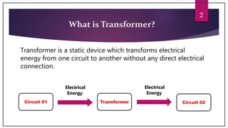
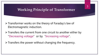
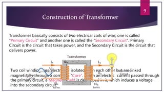
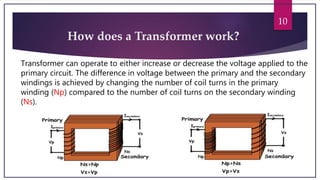
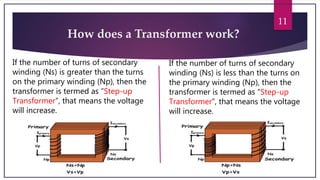
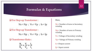
Single Phase Transformer
Presenter : S. M. Morshed Milu
Dept. : TE
Section : A
Id : 15-02-06-055
2
What is Transformer?
Transformer is a static device which transforms electrical
energy from one circuit to another without any direct electrical
connection.
Circuit 01 Transformer Circuit 02
Electrical
Energy
Electrical
Energy
3
Working Principle of Transformer
 Transformer works on the theory of Faraday’s law of
Electromagnetic induction.
 Transfers the current from one circuit to another either by
“Decreasing voltage” or by “Increasing voltage”.
 Transfers the power without changing the frequency.
4
Types of Transformer
Depending on the
Construction type:
Shell Type
Transformer
Core Type
Transformer
Depending on the power
handling capacity
Step-up Transformer
Step-down Transformer
Impedance
Transformer
5
Why do we need Transformer?
AC current can be generated at a convenient voltage at ‘Power Station’, which is
then transformed into much higher voltage to distribute by using ‘Step-up
Transformer' and then distributed all over the country through pylons and cables
over very long distances.
These higher AC transmission voltages can then be reduced to a much lower, safer
and usable voltage level by using ‘Step-down Transformer' where it can be used to
supply electrical equipment in our homes and workplaces. This chain of supplying
electricity to long distances is called “National Grid”.
6
Why the current is decreased?
Current is decreased, because if the high current is passed through the
connecting cables, big amount of Current Loss will happen due to the
Resisting Nature of cables. Since we know P=VR , even if the current is
decreased, Total Power can be kept same by increasing voltage.
National Grid
7
How does a Transformer look like?
Single Phase Transformer Three Phase Transformer
8
Different types of Transformer
Core Type Transformer :
In the “closed-core” type transformer,
the primary and secondary windings are
wound outside and surround the core
ring.
Shell Type Transformer :
Primary and secondary windings
pass inside the steel magnetic circuit
(core) which forms a shell around
the windings.
Step-up Transformer :
Transforms a low voltage associated
with the high current into a high voltage
(low current) from one circuit to
another.
Step-down Transformer :
Transforms a high voltage
associated with the low current into
a low voltage (high current) from
one circuit to another.
9
Construction of Transformer
Transformer basically consists of two electrical coils of wire, one is called
“Primary Circuit” and another one is called the “Secondary Circuit”. Primary
Circuit is the circuit that takes power, and the Secondary Circuit is the circuit that
delivers power.
Two coil windings are electrically isolated from each other but are linked
magnetically through a common “Core”. When an electric current passed through
the primary circuit, a Magnetic Field is developed in it, which induces a voltage
into the secondary circuit.
10
How does a Transformer work?
Transformer can operate to either increase or decrease the voltage applied to the
primary circuit. The difference in voltage between the primary and the secondary
windings is achieved by changing the number of coil turns in the primary
winding (Np) compared to the number of coil turns on the secondary winding
(Ns).
11
How does a Transformer work?
If the number of turns of secondary
winding (Ns) is greater than the turns
on the primary winding (Np), then the
transformer is termed as “Step-up
Transformer”, that means the voltage
will increase.
If the number of turns of secondary
winding (Ns) is less than the turns on
the primary winding (Np), then the
transformer is termed as “Step-up
Transformer”, that means the voltage
will increase.
12
Formulas & Equations
 For Step-up Transformer :
Ns > Np ; Vs > Vp ; Is < Ip
 For Step-up Transformer :
Ns > Np ; Vs > Vp ; Is < Ip
Ns
Np
=
Vs
Vp
=
Ip
Is
 Transformer Ratio :
Here,
Ns = Number of turns in Secondary
winding
Np = Number of turns in Primary
winding
Vs = Voltage of Secondary winding
Vp = Voltage of Primary winding
Is = Output current
Ip = Input current
13
Any Question?
Transformer

Transformer

  • 1.
    Single Phase Transformer Presenter: S. M. Morshed Milu Dept. : TE Section : A Id : 15-02-06-055
  • 2.
    2 What is Transformer? Transformeris a static device which transforms electrical energy from one circuit to another without any direct electrical connection. Circuit 01 Transformer Circuit 02 Electrical Energy Electrical Energy
  • 3.
    3 Working Principle ofTransformer  Transformer works on the theory of Faraday’s law of Electromagnetic induction.  Transfers the current from one circuit to another either by “Decreasing voltage” or by “Increasing voltage”.  Transfers the power without changing the frequency.
  • 4.
    4 Types of Transformer Dependingon the Construction type: Shell Type Transformer Core Type Transformer Depending on the power handling capacity Step-up Transformer Step-down Transformer Impedance Transformer
  • 5.
    5 Why do weneed Transformer? AC current can be generated at a convenient voltage at ‘Power Station’, which is then transformed into much higher voltage to distribute by using ‘Step-up Transformer' and then distributed all over the country through pylons and cables over very long distances. These higher AC transmission voltages can then be reduced to a much lower, safer and usable voltage level by using ‘Step-down Transformer' where it can be used to supply electrical equipment in our homes and workplaces. This chain of supplying electricity to long distances is called “National Grid”.
  • 6.
    6 Why the currentis decreased? Current is decreased, because if the high current is passed through the connecting cables, big amount of Current Loss will happen due to the Resisting Nature of cables. Since we know P=VR , even if the current is decreased, Total Power can be kept same by increasing voltage. National Grid
  • 7.
    7 How does aTransformer look like? Single Phase Transformer Three Phase Transformer
  • 8.
    8 Different types ofTransformer Core Type Transformer : In the “closed-core” type transformer, the primary and secondary windings are wound outside and surround the core ring. Shell Type Transformer : Primary and secondary windings pass inside the steel magnetic circuit (core) which forms a shell around the windings. Step-up Transformer : Transforms a low voltage associated with the high current into a high voltage (low current) from one circuit to another. Step-down Transformer : Transforms a high voltage associated with the low current into a low voltage (high current) from one circuit to another.
  • 9.
    9 Construction of Transformer Transformerbasically consists of two electrical coils of wire, one is called “Primary Circuit” and another one is called the “Secondary Circuit”. Primary Circuit is the circuit that takes power, and the Secondary Circuit is the circuit that delivers power. Two coil windings are electrically isolated from each other but are linked magnetically through a common “Core”. When an electric current passed through the primary circuit, a Magnetic Field is developed in it, which induces a voltage into the secondary circuit.
  • 10.
    10 How does aTransformer work? Transformer can operate to either increase or decrease the voltage applied to the primary circuit. The difference in voltage between the primary and the secondary windings is achieved by changing the number of coil turns in the primary winding (Np) compared to the number of coil turns on the secondary winding (Ns).
  • 11.
    11 How does aTransformer work? If the number of turns of secondary winding (Ns) is greater than the turns on the primary winding (Np), then the transformer is termed as “Step-up Transformer”, that means the voltage will increase. If the number of turns of secondary winding (Ns) is less than the turns on the primary winding (Np), then the transformer is termed as “Step-up Transformer”, that means the voltage will increase.
  • 12.
    12 Formulas & Equations For Step-up Transformer : Ns > Np ; Vs > Vp ; Is < Ip  For Step-up Transformer : Ns > Np ; Vs > Vp ; Is < Ip Ns Np = Vs Vp = Ip Is  Transformer Ratio : Here, Ns = Number of turns in Secondary winding Np = Number of turns in Primary winding Vs = Voltage of Secondary winding Vp = Voltage of Primary winding Is = Output current Ip = Input current
  • 13.