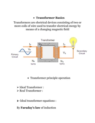
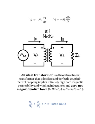
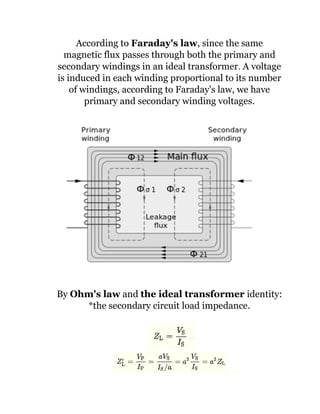
Al Azhar university
Faculty of Engineering, Qena
Electrical Engineering Department
Report About
Transformer
Under the Supervision of
Eng. Mohamed El-Safy
Eng. Abdallah Farahat
Name. Mustafa Mamdoh Abdel Azeez
Second Year
2019
• Transformer Basics
Transformers are electrical devices consisting of two or
more coils of wire used to transfer electrical energy by
means of a changing magnetic field
• Transformer principle operation
➢ Ideal Transformer :
➢ Real Transformer :
1- Ideal transformer equations :
By Faraday's law of induction
An ideal transformer is a theoretical linear
transformer that is lossless and perfectly coupled ،
Perfect coupling implies infinitely high core magnetic
permeability and winding inductances and zero net
magnetomotive force (MMF=0) ( ip*Np - is*Ns = 0 ).
According to Faraday's law, since the same
magnetic flux passes through both the primary and
secondary windings in an ideal transformer. A voltage
is induced in each winding proportional to its number
of windings, according to Faraday's law, we have
primary and secondary winding voltages.
By Ohm's law and the ideal transformer identity:
*the secondary circuit load impedance.
*The apparent load impedance referred to the primary
circuit to be equal to the turns ratio squared times the
secondary circuit load impedance.
2- The Real transformer is model neglects the
following basic linear aspects of real transformers:
(a) Core losses, collectively called magnetizing
current losses, consisting of
➢ Hysteresis losses due to nonlinear magnetic
effects in the transformer core.
➢ Eddy current losses due to joule heating in the
core that are proportional to the square of the
transformer's applied voltage.
(b) Unlike the ideal model, the windings in a real
transformer have non-zero resistances and
inductances associated with:
➢ Joule losses due to resistance in the primary
and secondary windings (Copper loss).
➢ Leakage flux that escapes from the core and
passes through one winding only resulting in
primary and secondary reactive impedance.
• Transformer Construction
➢ Core
➢ Laminated steel core
➢ Windings
• Cooling of Transformer
Cooling of a transformer is the process of dissipation of
heat developed in the transformer to the surroundings ،
the losses occurring in the transformer are converted into
heat which increases the temperature of the windings and
the core. In order to dissipate the heat generated cooling
should be done.
*Methods of Cooling of Transformer:
1. Air cooling
2. Oil and Air cooling
3. Oil and Water cooling
• Types of Transformer
➢ Core type
➢ Shell type
• Test of Transformer
Open Circuit and Short Circuit Test on Transformer:
These two transformer tests are performed to find the
parameters of equivalent circuit of transformer and losses
of the transformer and they are very economical and
convenient because they are performed without actually
loading of the transformer.
➢ Open Circuit Test “No Load”
➢ Short Circuit Test
• Voltage Regulation
The voltage regulation: of the transformer is the
percentage change in the output voltage from no-load to
full-load and since power factor is a determining factor in
the secondary voltage, power factor influences voltage
regulation.
This means the voltage regulation of a transformer is a
dynamic, load-dependent number. The numbers you see in
the nameplate data are fixed; the number of primary
windings won't change; the number of secondary windings
won't change, etc.
But the voltage regulation will vary as power factor varies.
In electrical engineering, particularly power engineering,
voltage regulation is a measure of change in the voltage
magnitude between the sending and receiving end of a
component, such as a transmission or distribution line.
Voltage regulation describes the ability of a system to
provide near constant voltage over a wide range of load
conditions.
The term may refer to a passive property that results in
more or less voltage drop under various load conditions, or
to the active intervention with devices for the specific
purpose of adjusting voltage.

Transformer

  • 1.
    Al Azhar university Facultyof Engineering, Qena Electrical Engineering Department Report About Transformer Under the Supervision of Eng. Mohamed El-Safy Eng. Abdallah Farahat Name. Mustafa Mamdoh Abdel Azeez Second Year 2019
  • 2.
    • Transformer Basics Transformersare electrical devices consisting of two or more coils of wire used to transfer electrical energy by means of a changing magnetic field • Transformer principle operation ➢ Ideal Transformer : ➢ Real Transformer : 1- Ideal transformer equations : By Faraday's law of induction
  • 3.
    An ideal transformeris a theoretical linear transformer that is lossless and perfectly coupled ، Perfect coupling implies infinitely high core magnetic permeability and winding inductances and zero net magnetomotive force (MMF=0) ( ip*Np - is*Ns = 0 ).
  • 4.
    According to Faraday'slaw, since the same magnetic flux passes through both the primary and secondary windings in an ideal transformer. A voltage is induced in each winding proportional to its number of windings, according to Faraday's law, we have primary and secondary winding voltages. By Ohm's law and the ideal transformer identity: *the secondary circuit load impedance.
  • 5.
    *The apparent loadimpedance referred to the primary circuit to be equal to the turns ratio squared times the secondary circuit load impedance. 2- The Real transformer is model neglects the following basic linear aspects of real transformers: (a) Core losses, collectively called magnetizing current losses, consisting of ➢ Hysteresis losses due to nonlinear magnetic effects in the transformer core. ➢ Eddy current losses due to joule heating in the core that are proportional to the square of the transformer's applied voltage. (b) Unlike the ideal model, the windings in a real transformer have non-zero resistances and inductances associated with: ➢ Joule losses due to resistance in the primary and secondary windings (Copper loss). ➢ Leakage flux that escapes from the core and passes through one winding only resulting in primary and secondary reactive impedance.
  • 6.
  • 7.
    ➢ Core ➢ Laminatedsteel core ➢ Windings • Cooling of Transformer Cooling of a transformer is the process of dissipation of heat developed in the transformer to the surroundings ، the losses occurring in the transformer are converted into heat which increases the temperature of the windings and the core. In order to dissipate the heat generated cooling should be done. *Methods of Cooling of Transformer: 1. Air cooling 2. Oil and Air cooling 3. Oil and Water cooling • Types of Transformer ➢ Core type ➢ Shell type
  • 8.
    • Test ofTransformer Open Circuit and Short Circuit Test on Transformer: These two transformer tests are performed to find the parameters of equivalent circuit of transformer and losses of the transformer and they are very economical and convenient because they are performed without actually loading of the transformer. ➢ Open Circuit Test “No Load” ➢ Short Circuit Test
  • 9.
    • Voltage Regulation Thevoltage regulation: of the transformer is the percentage change in the output voltage from no-load to full-load and since power factor is a determining factor in the secondary voltage, power factor influences voltage regulation. This means the voltage regulation of a transformer is a dynamic, load-dependent number. The numbers you see in the nameplate data are fixed; the number of primary windings won't change; the number of secondary windings won't change, etc. But the voltage regulation will vary as power factor varies.
  • 10.
    In electrical engineering,particularly power engineering, voltage regulation is a measure of change in the voltage magnitude between the sending and receiving end of a component, such as a transmission or distribution line. Voltage regulation describes the ability of a system to provide near constant voltage over a wide range of load conditions. The term may refer to a passive property that results in more or less voltage drop under various load conditions, or to the active intervention with devices for the specific purpose of adjusting voltage.