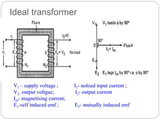
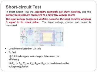
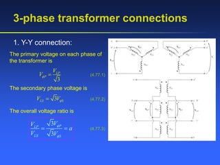
This document provides an overview of transformers, including:
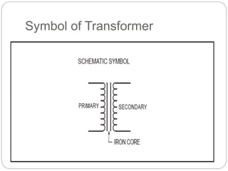
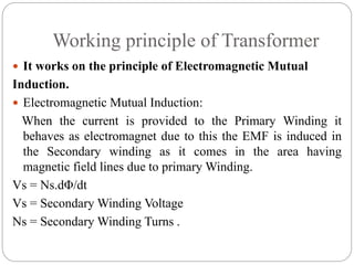
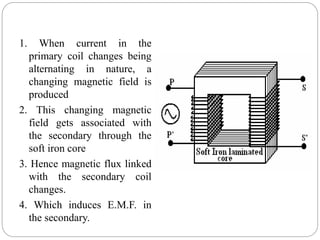
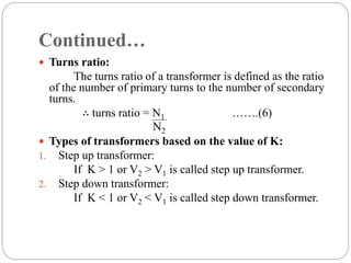
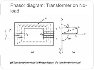
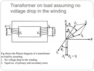
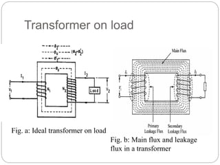
- The basic components and working principle of transformers based on electromagnetic induction.
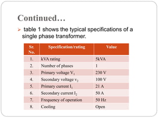
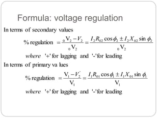
- The need for transformers to adjust voltages for transmission and household use by stepping up or down voltages.
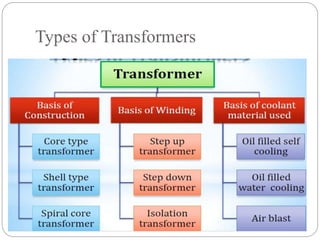
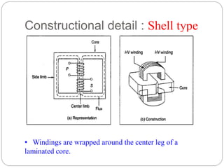
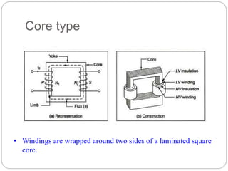
- Types of transformer construction including shell and core types.
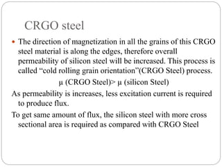
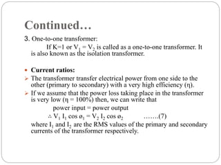
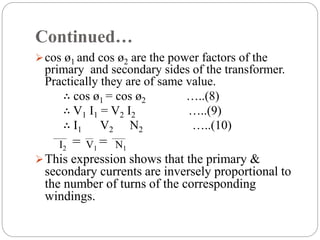
- Key factors that affect transformer performance like core material properties, turns ratio, and equations for ideal transformer voltage and current ratios.
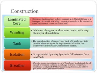
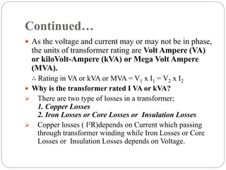
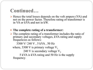
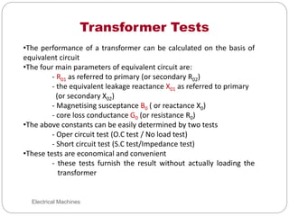
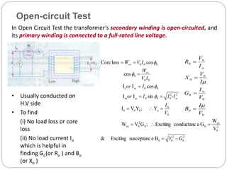
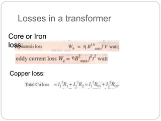
- Sources of transformer losses and factors considered in transformer design like core material selection and lamination to reduce losses.

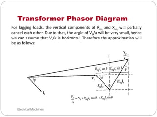
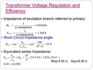
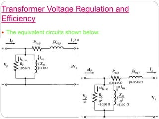
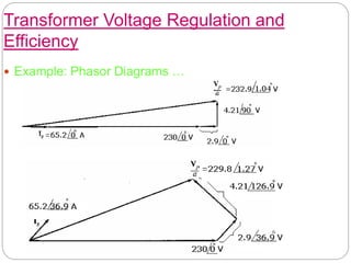
![Transformer Voltage Regulation and
Efficiency
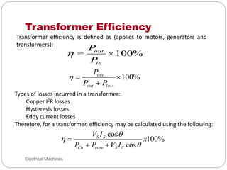
(e) Efficiency of Transformer:
- Copper losses:
PCu=(IS)²Req =(65.2)² (0.0445)=189 W
- Core losses:
PCore= (VP/a)² / RC= (234.85)² / 1050=52.5 W
output power:
Pout=VSIS cosθ=230x65.2xcos36.9◦=12000 W
η= VSIS cosθ / [PCu+PCore+VSIS cosθ] x 100%=
12000/ [189+52.5+12000] = 98.03 %](https://image.slidesharecdn.com/module-4transformers-240125161413-051eb8f0/85/module-4-TRANSFORMER-pptx-92-320.jpg)


![Chapter 4 dc machine [autosaved]](https://cdn.slidesharecdn.com/ss_thumbnails/chapter4-dcmachineautosaved-140915220206-phpapp01-thumbnail.jpg?width=640&height=640&fit=bounds)


