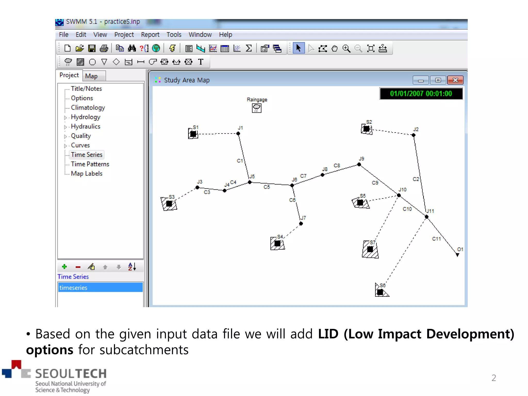
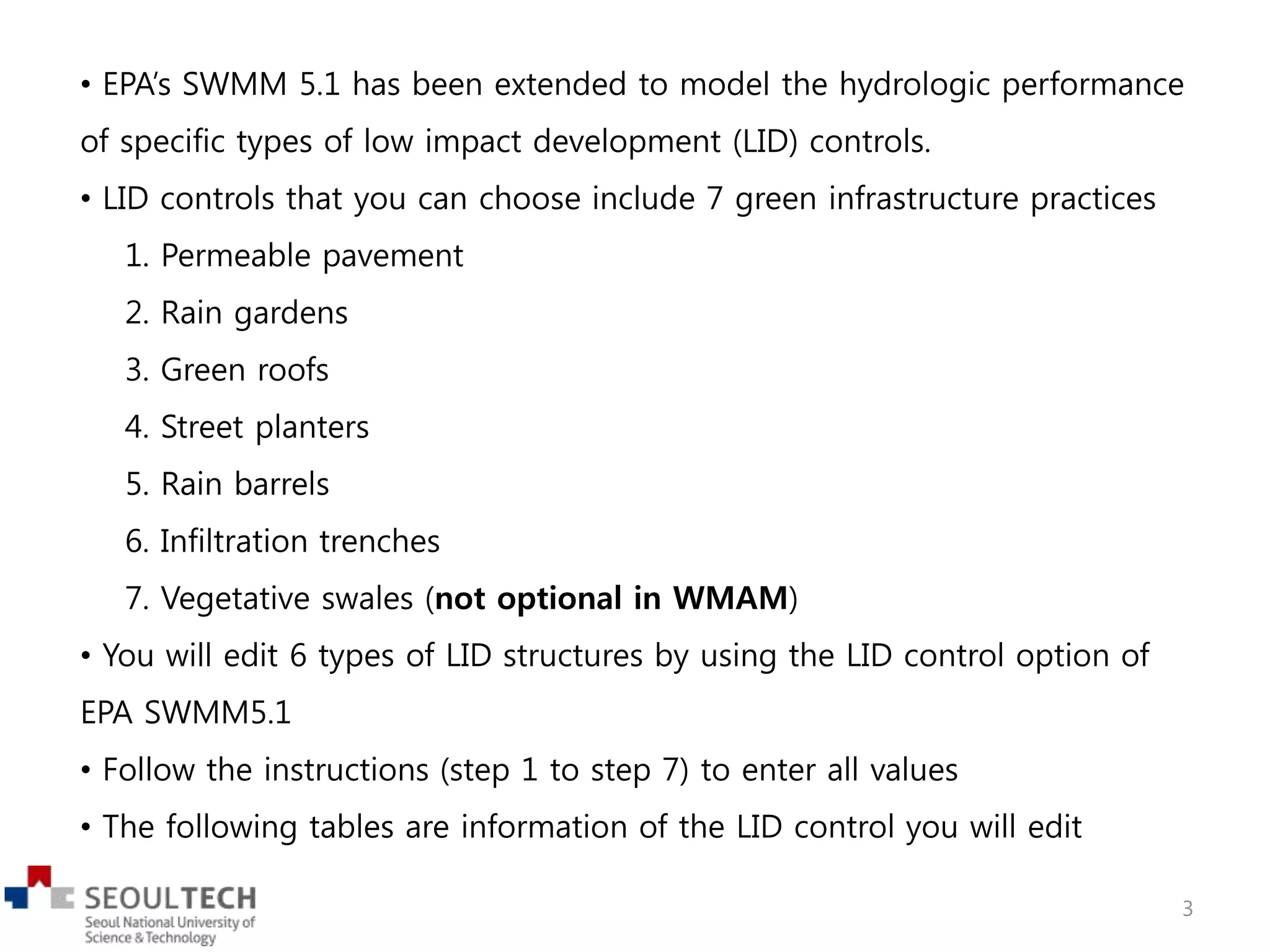
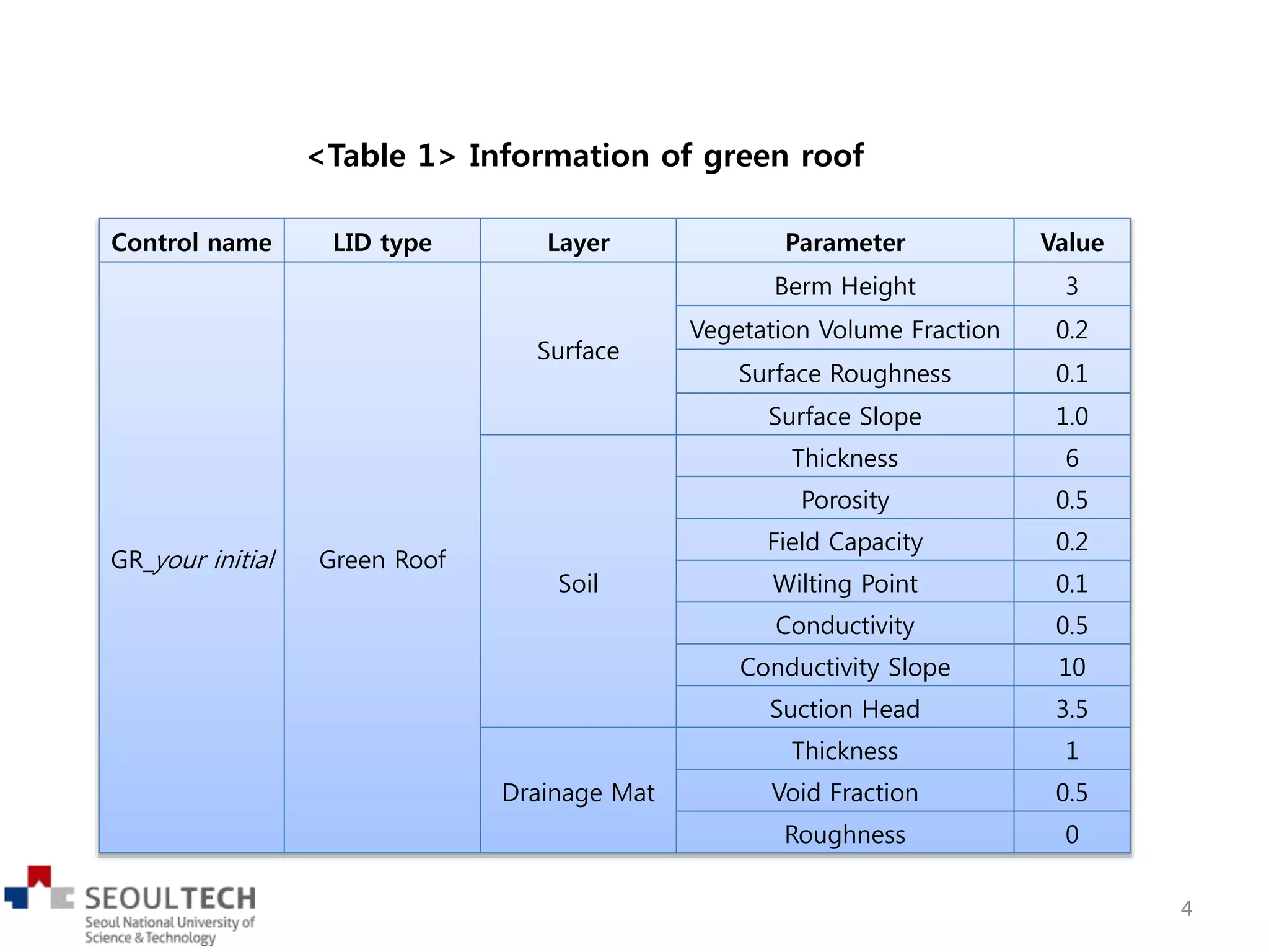
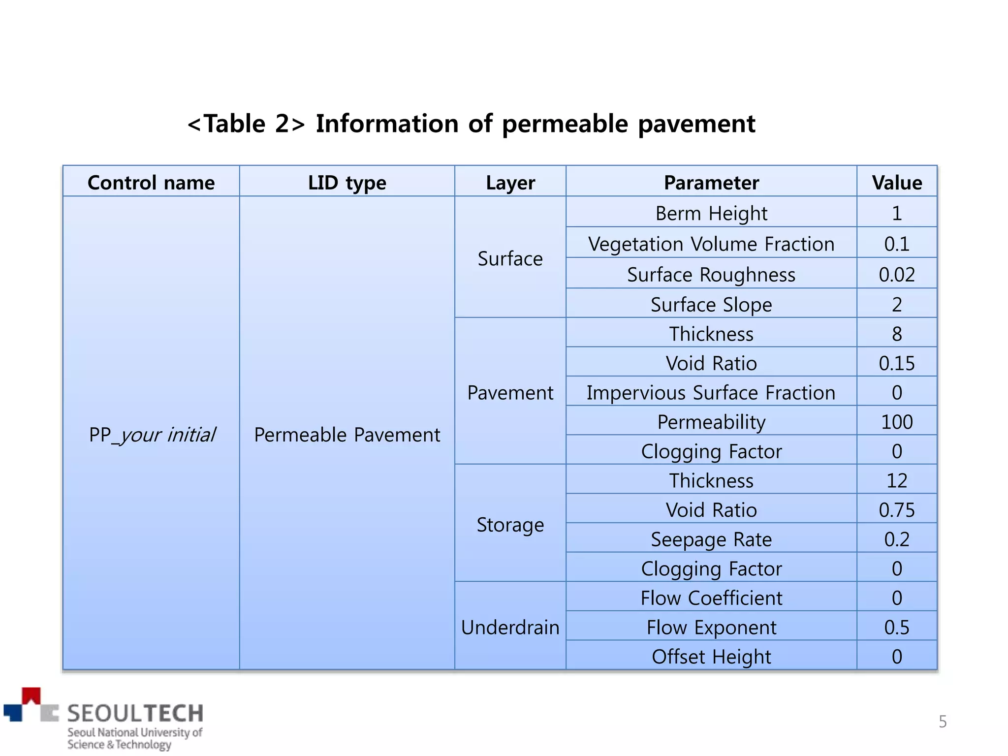
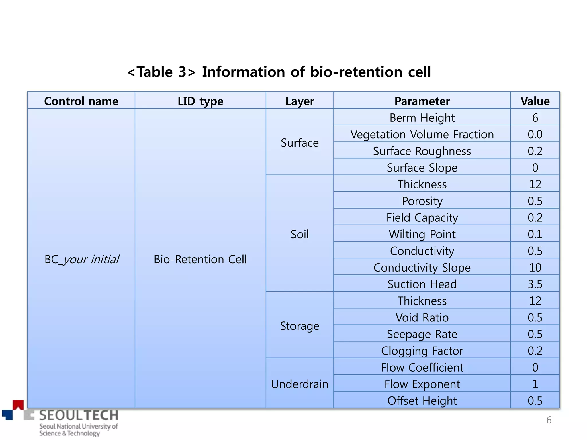
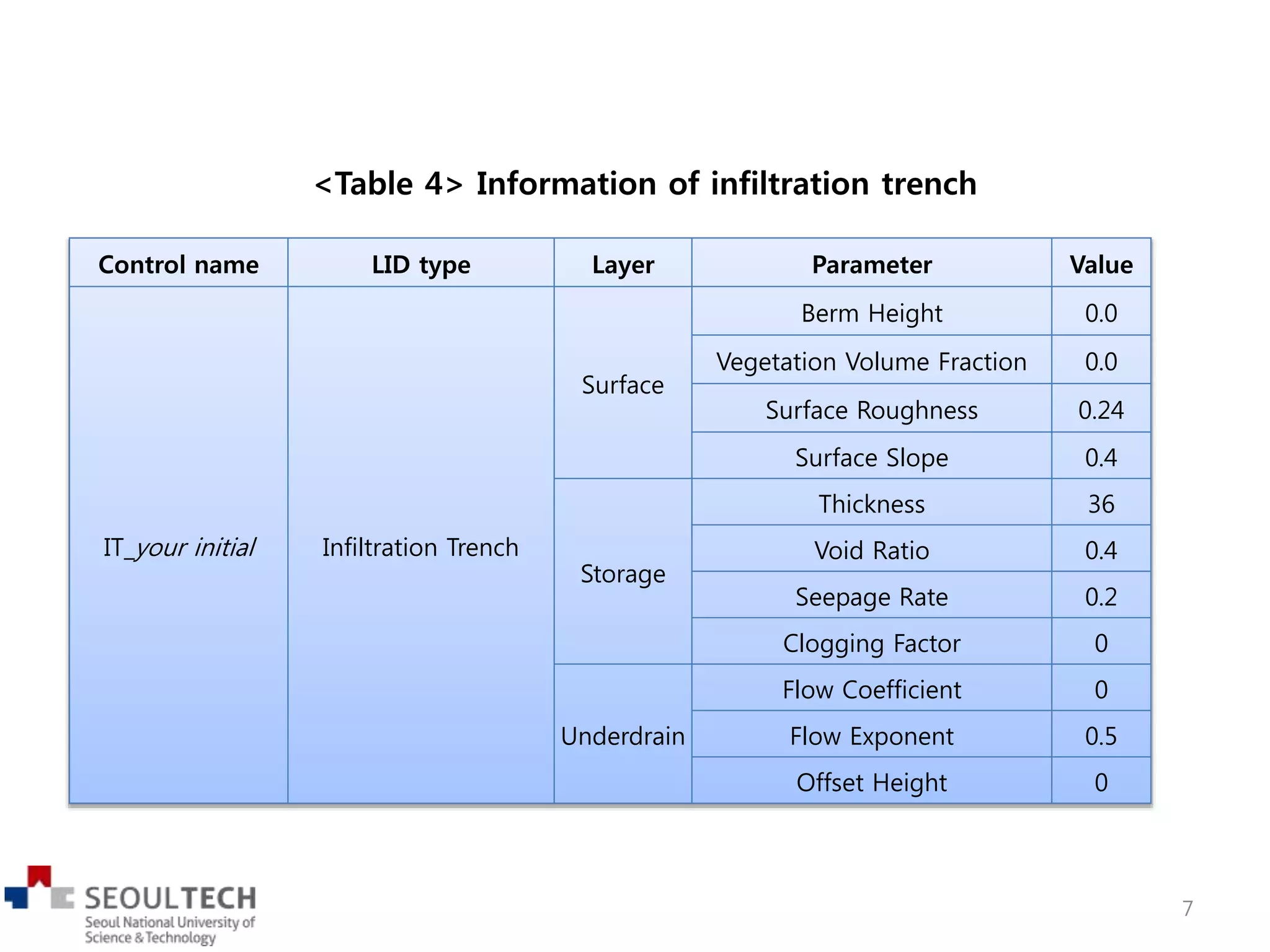
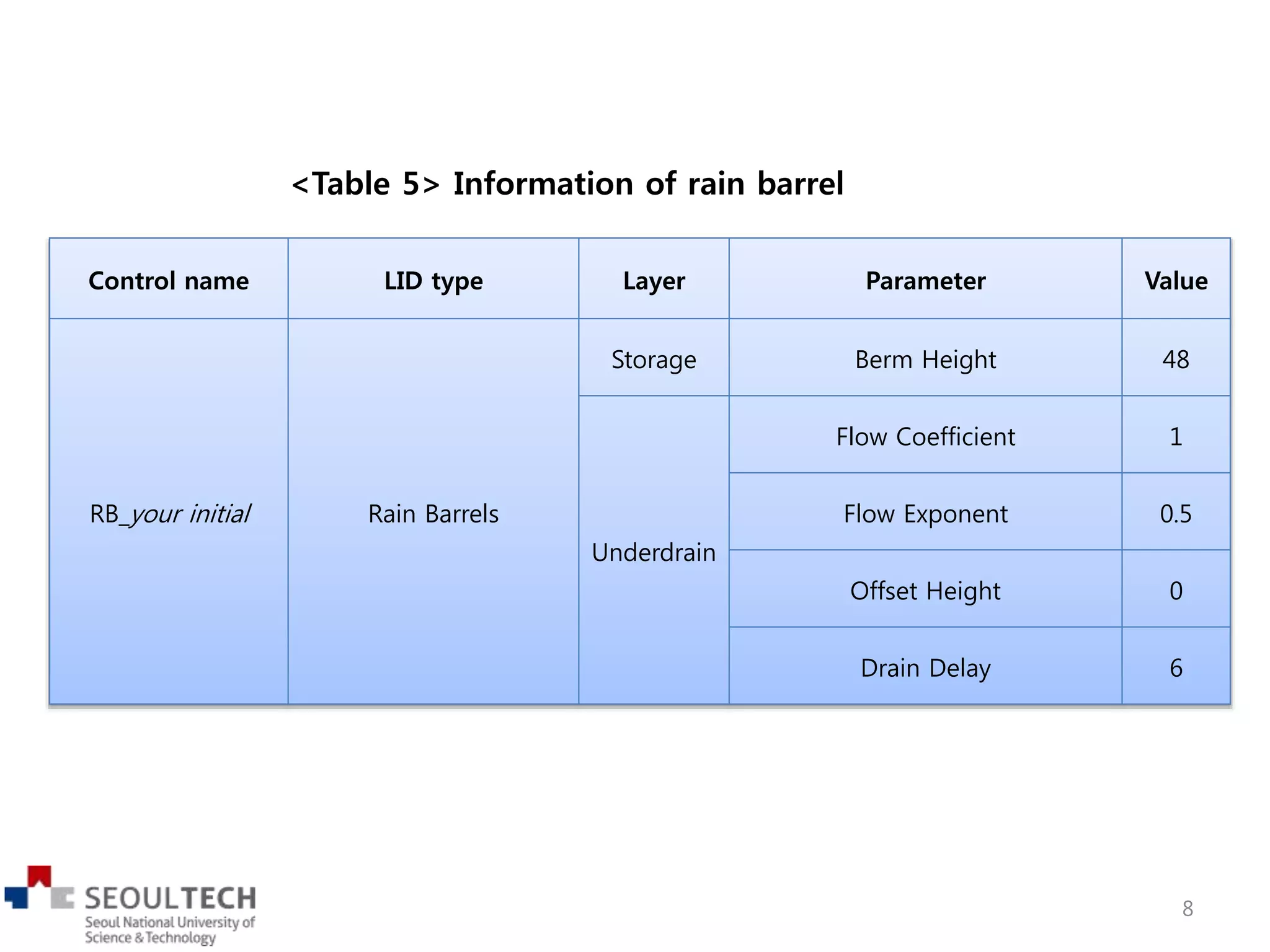
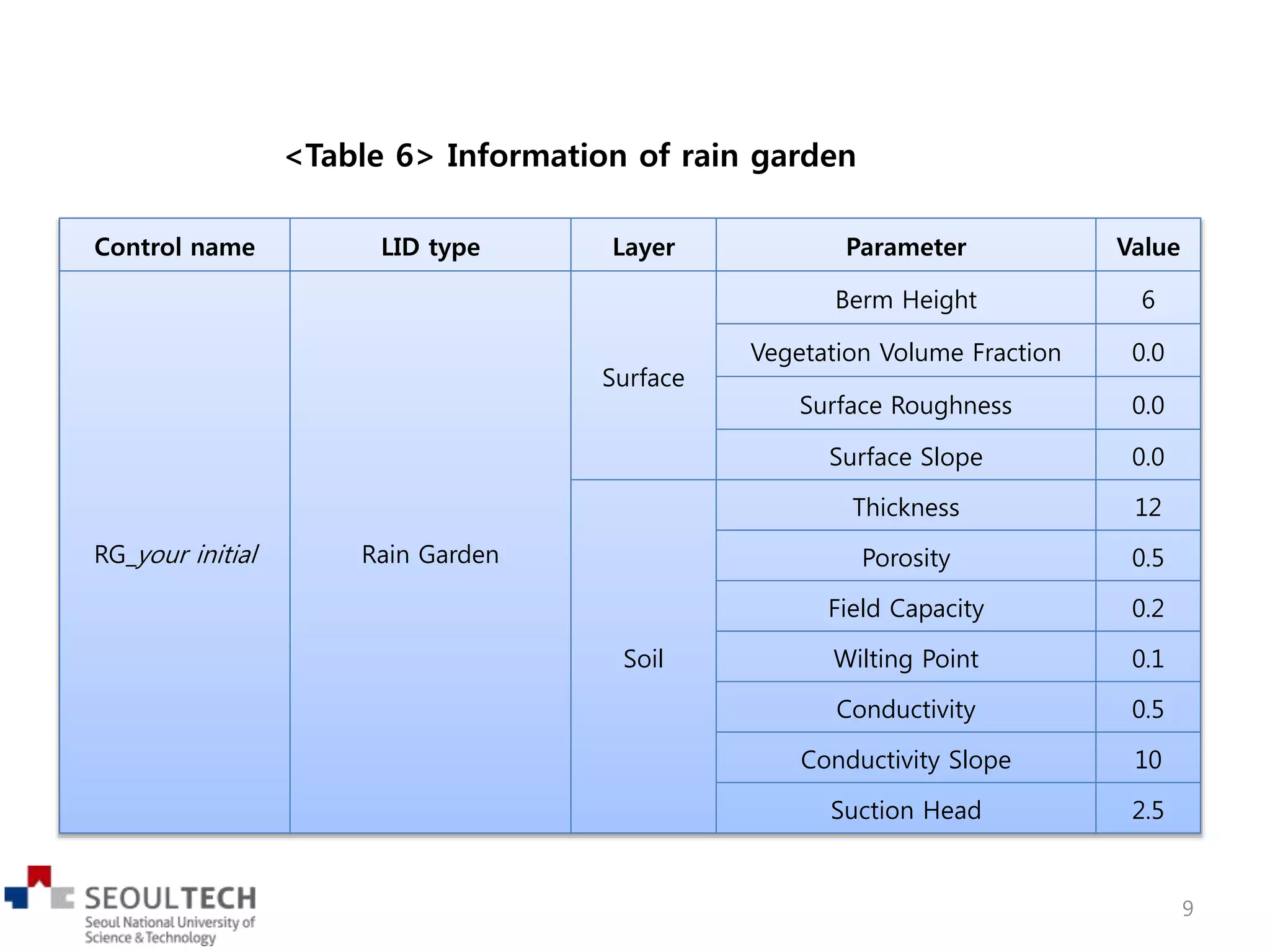
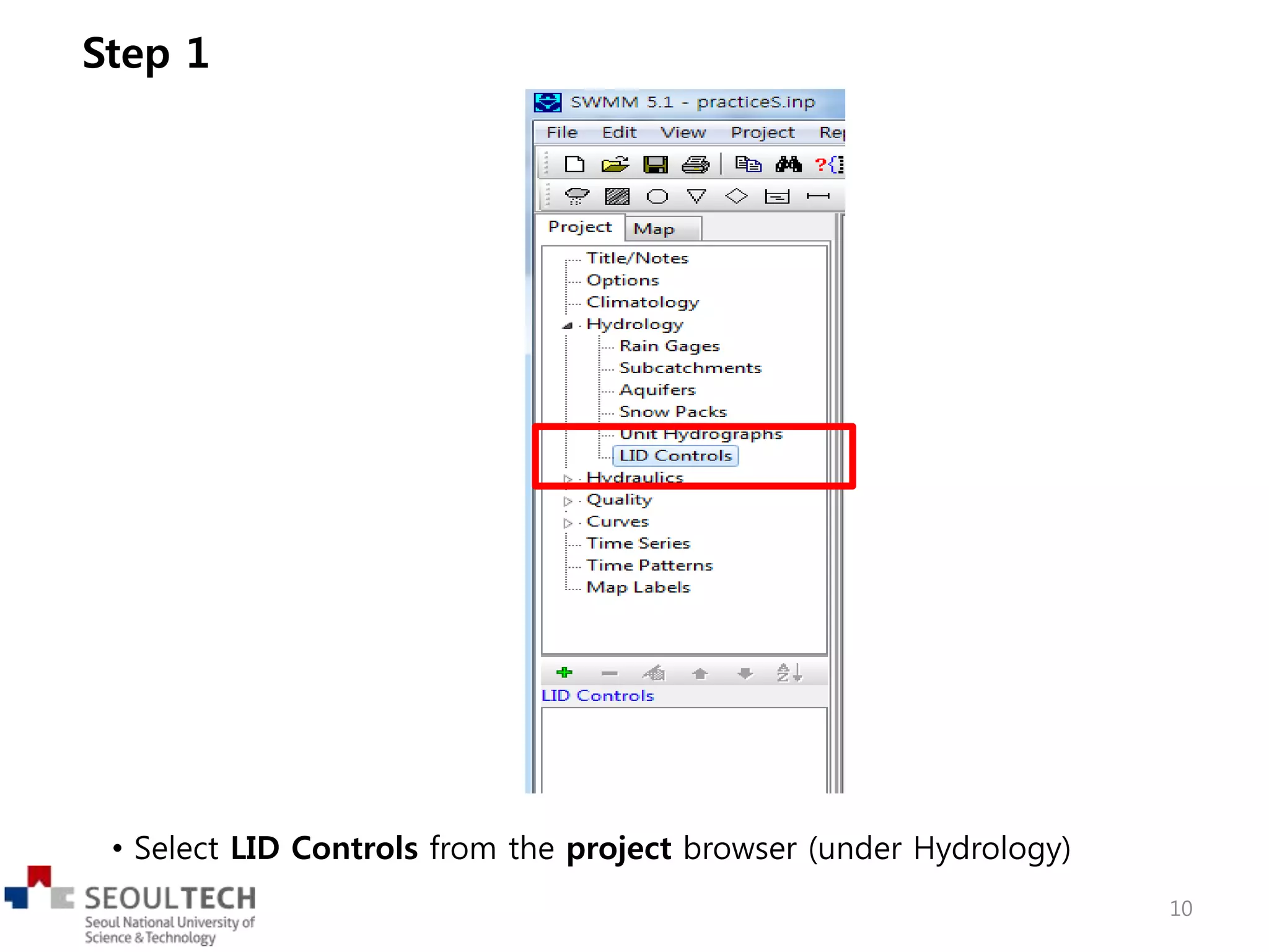
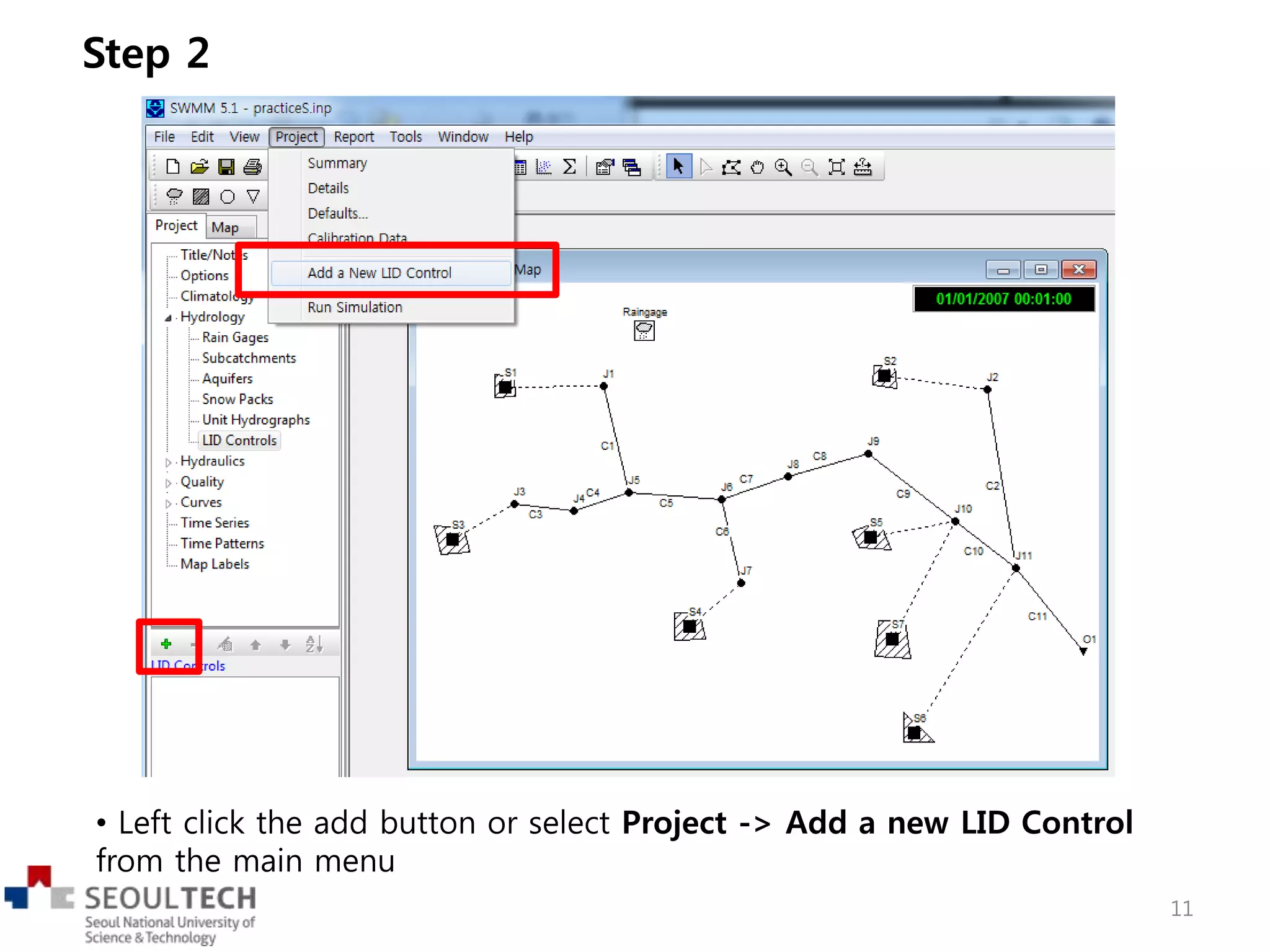
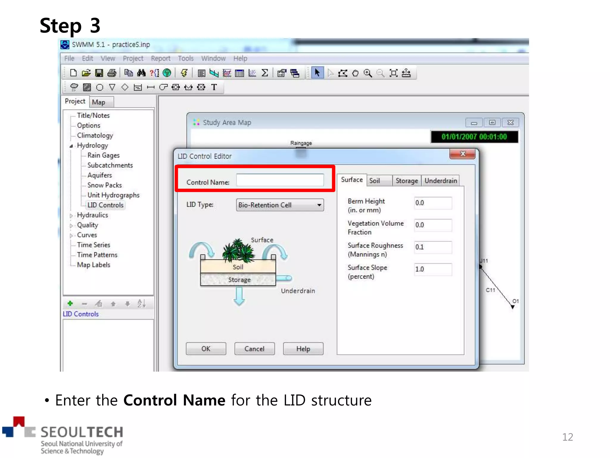
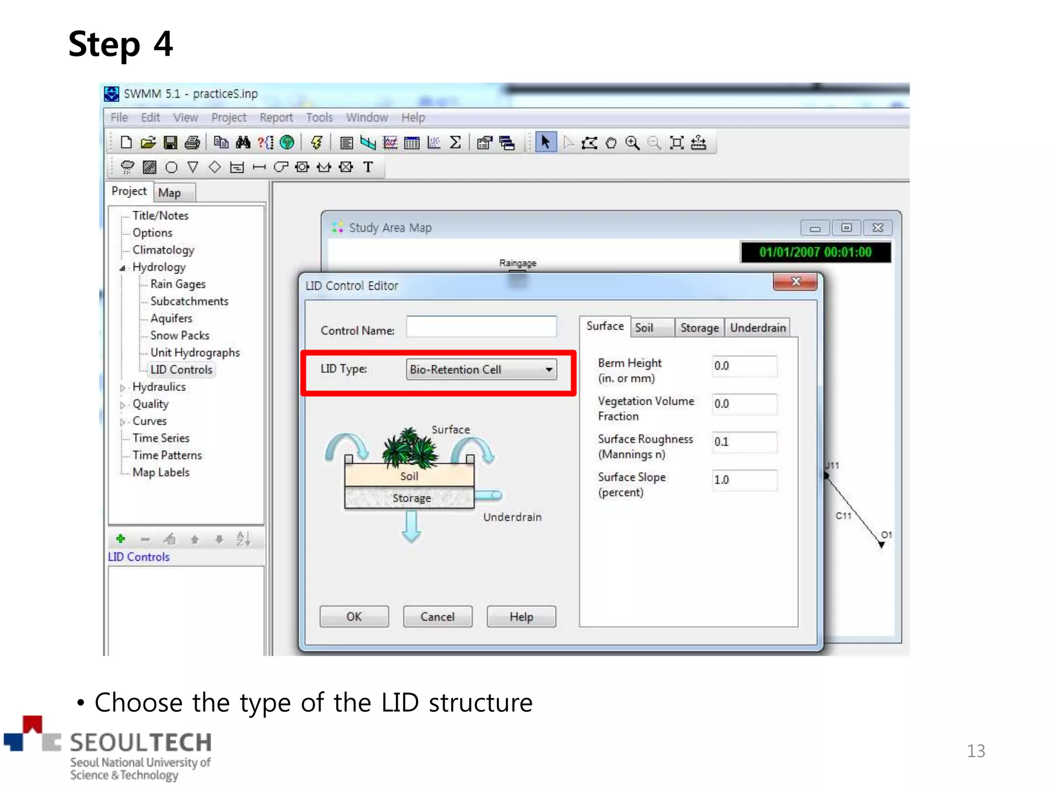
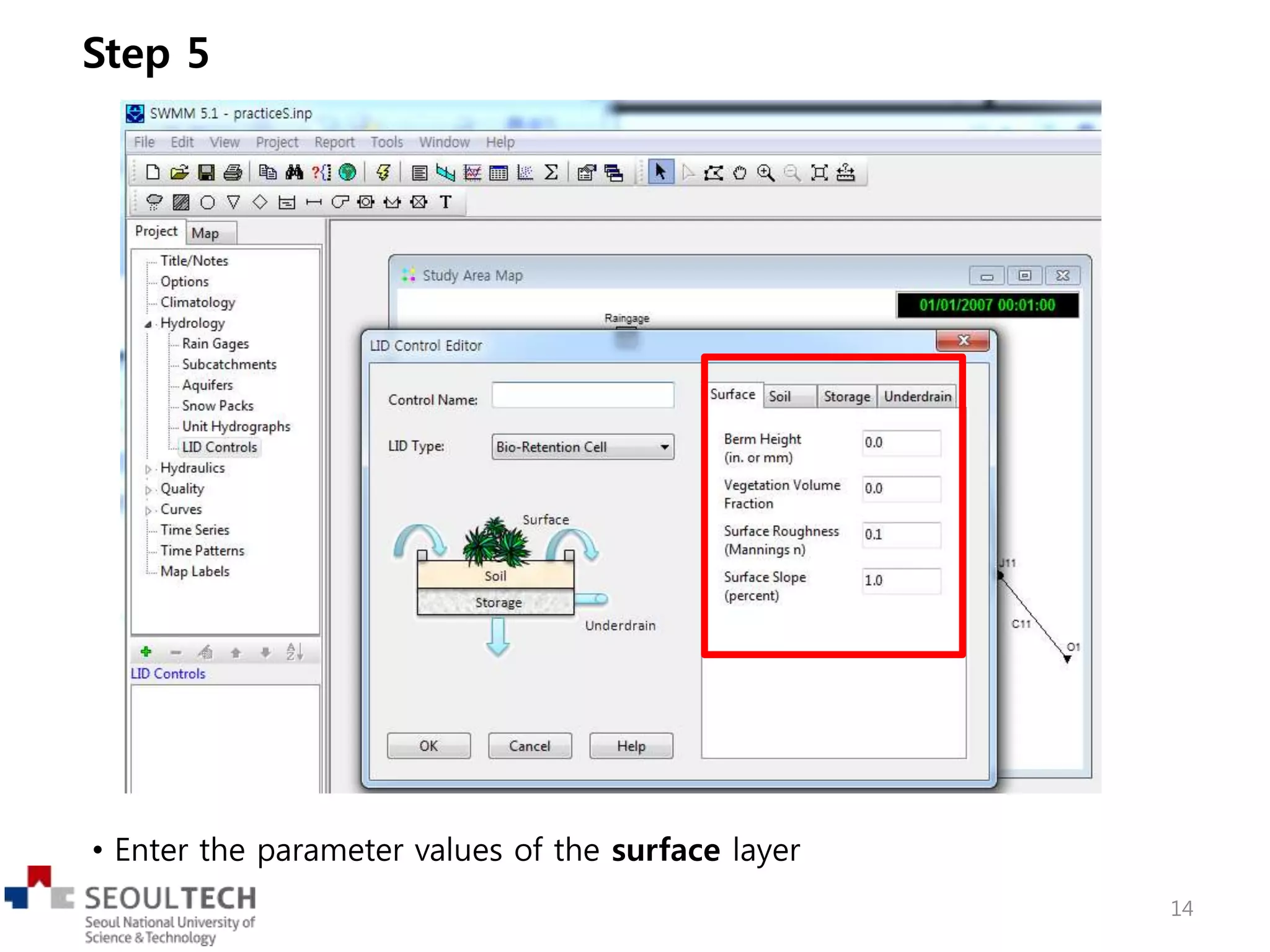
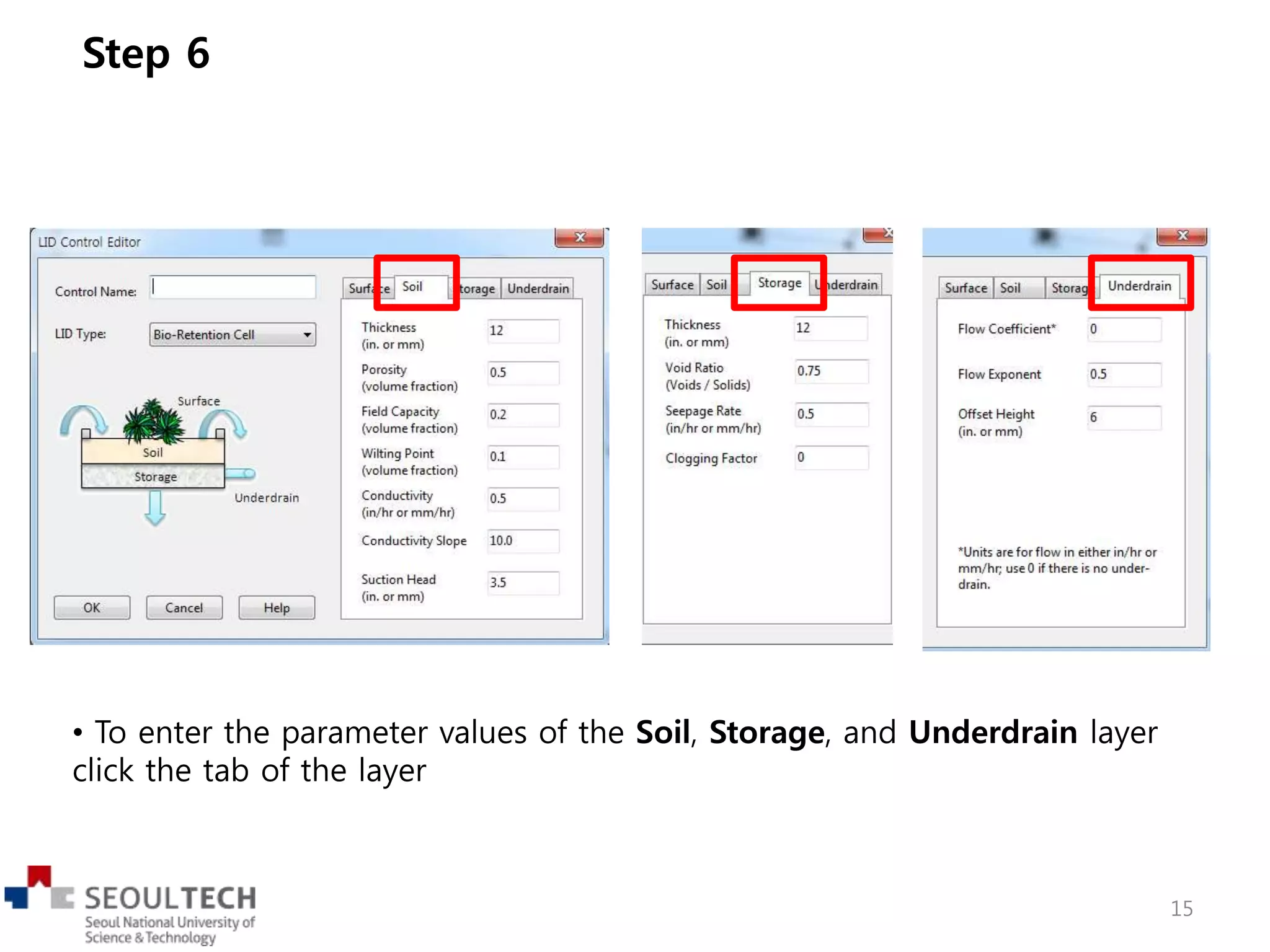
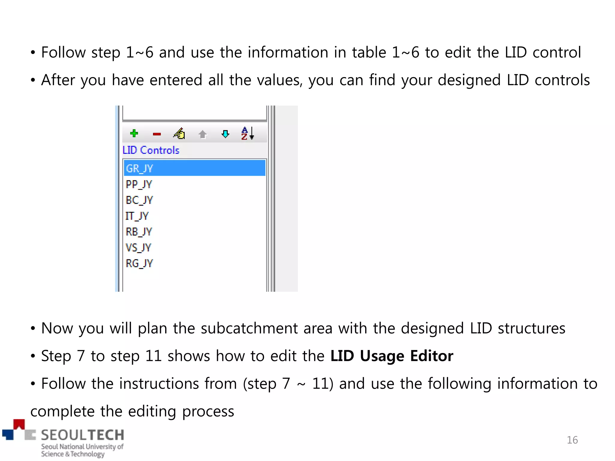
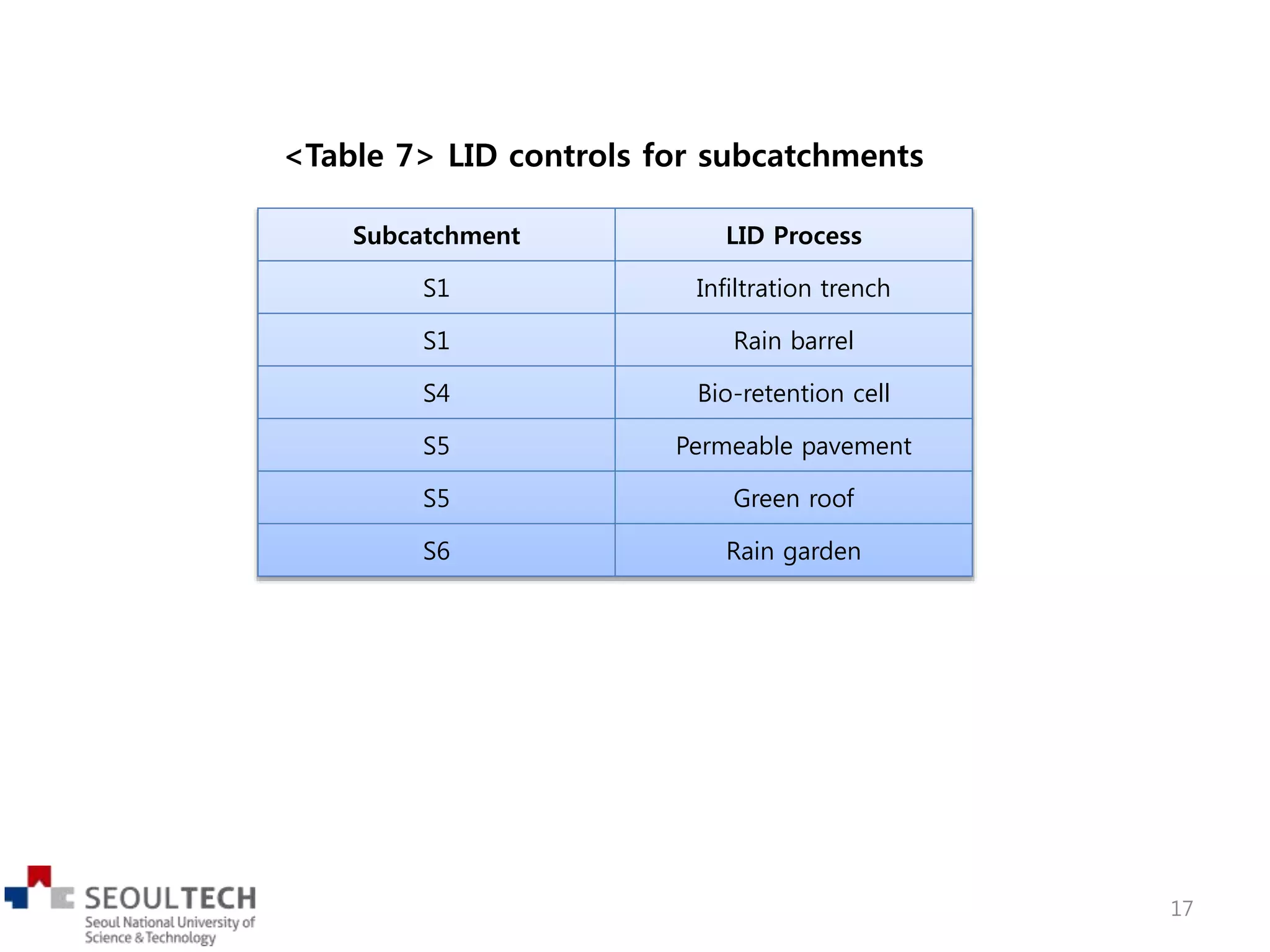
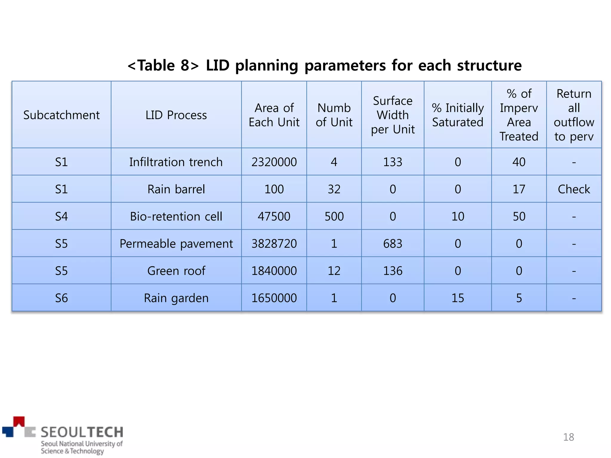
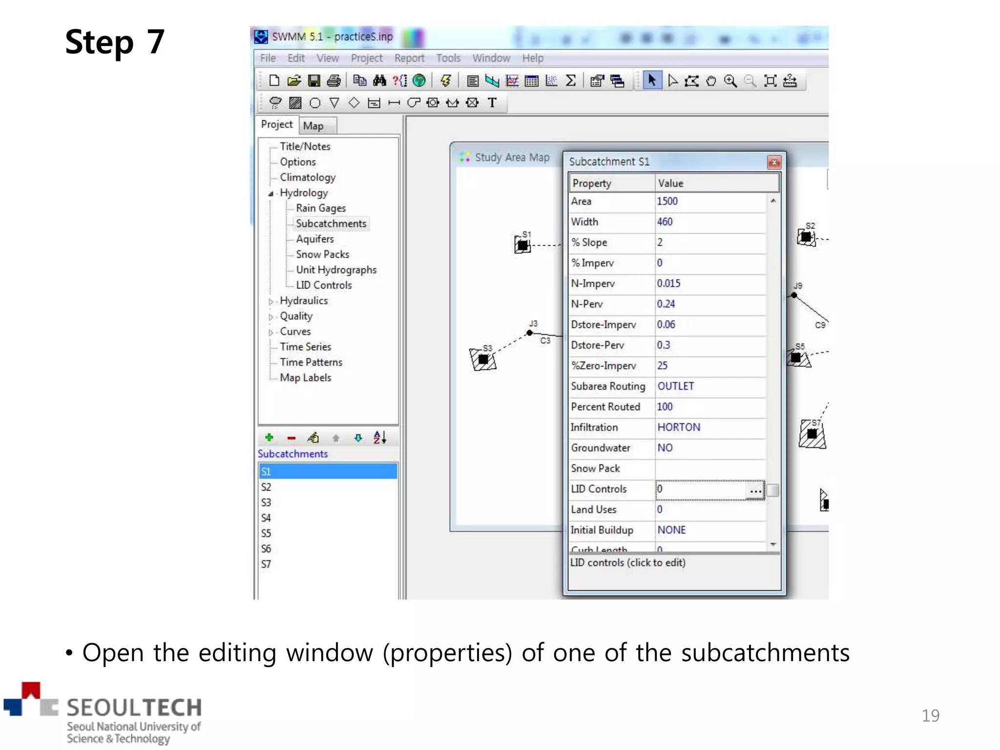
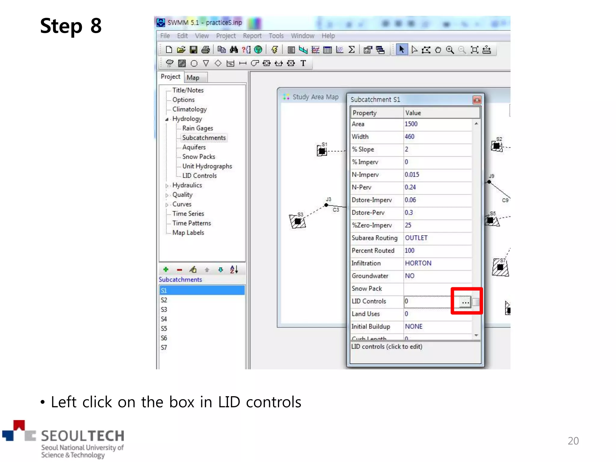
This document provides instructions for adding low impact development (LID) controls to subcatchments in EPA's SWMM 5.1 hydrological model. It describes how to design 6 types of LID controls by specifying their layer parameters. Tables are provided giving parameter values for green roofs, permeable pavement, bio-retention cells, infiltration trenches, rain barrels, and rain gardens. The document then explains how to assign these designed LID controls to different subcatchments and input their planning parameters.
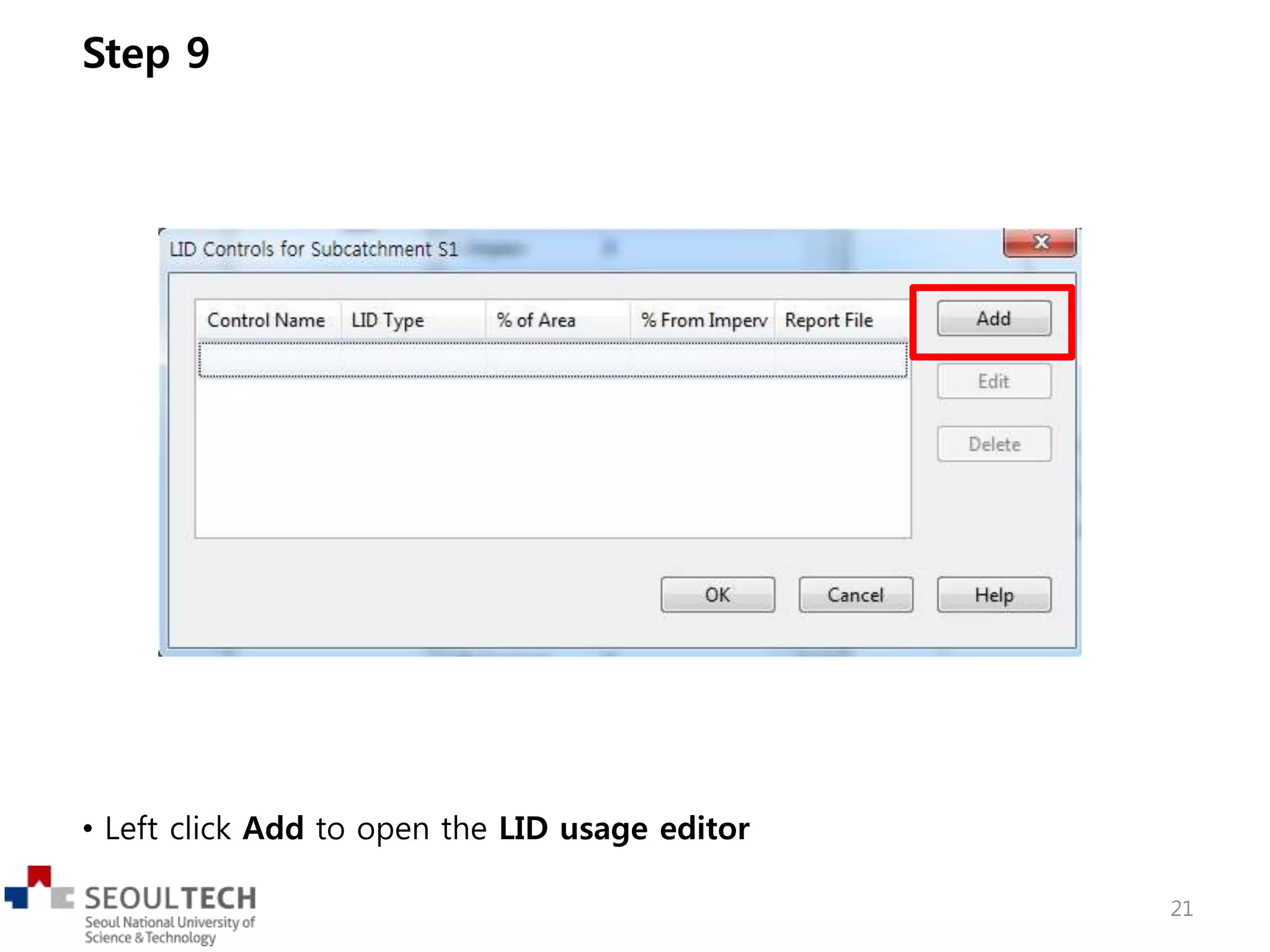
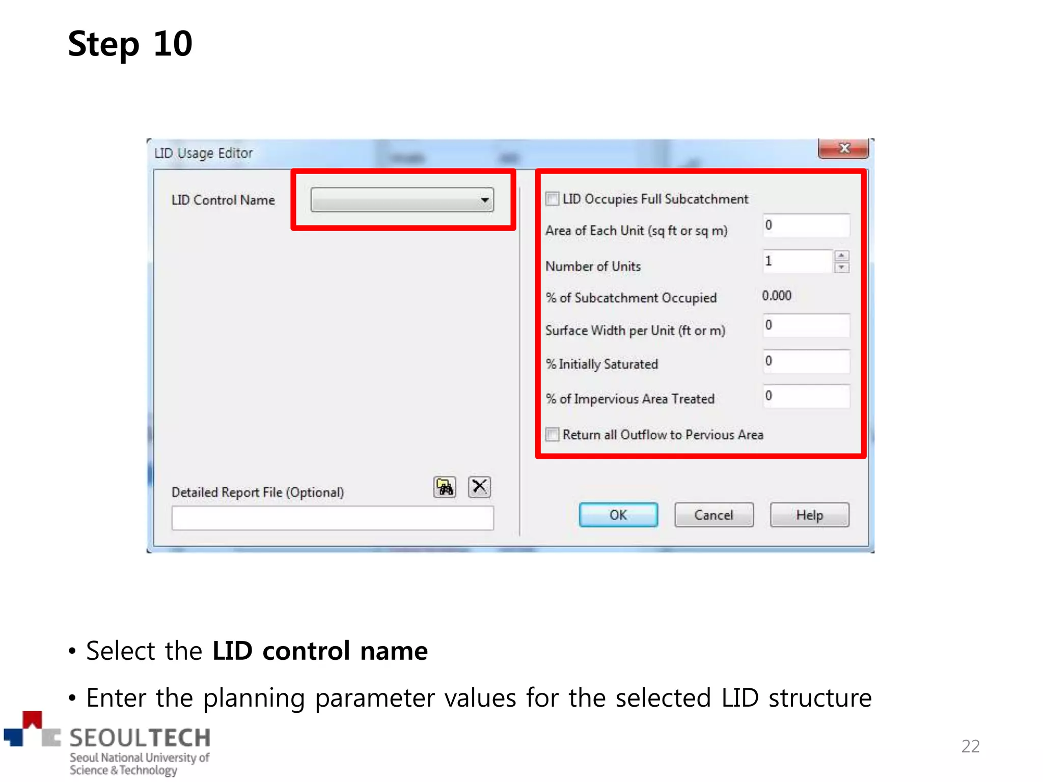
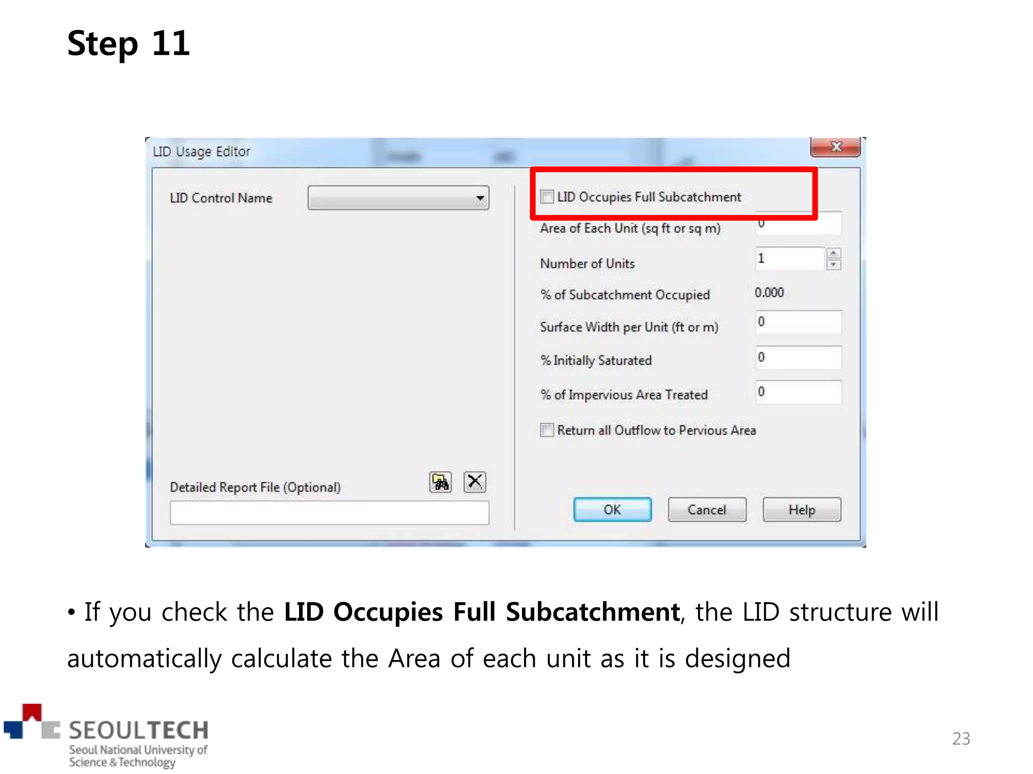


![APR 23 10 LIVING WITH LID [Compatibility Mode]](https://cdn.slidesharecdn.com/ss_thumbnails/cfdcf478-6a89-479c-adea-209acd3d86ae-150406172555-conversion-gate01-thumbnail.jpg?width=640&height=640&fit=bounds)


